EP0508085A2 - Tuyau d'installation ou de descente avec collier pour tuyau - Google Patents
Tuyau d'installation ou de descente avec collier pour tuyau Download PDFInfo
- Publication number
- EP0508085A2 EP0508085A2 EP92103376A EP92103376A EP0508085A2 EP 0508085 A2 EP0508085 A2 EP 0508085A2 EP 92103376 A EP92103376 A EP 92103376A EP 92103376 A EP92103376 A EP 92103376A EP 0508085 A2 EP0508085 A2 EP 0508085A2
- Authority
- EP
- European Patent Office
- Prior art keywords
- pipe clamp
- individual
- clamp according
- elements
- pipe
- Prior art date
- Legal status (The legal status is an assumption and is not a legal conclusion. Google has not performed a legal analysis and makes no representation as to the accuracy of the status listed.)
- Granted
Links
Images
Classifications
-
- F—MECHANICAL ENGINEERING; LIGHTING; HEATING; WEAPONS; BLASTING
- F16—ENGINEERING ELEMENTS AND UNITS; GENERAL MEASURES FOR PRODUCING AND MAINTAINING EFFECTIVE FUNCTIONING OF MACHINES OR INSTALLATIONS; THERMAL INSULATION IN GENERAL
- F16L—PIPES; JOINTS OR FITTINGS FOR PIPES; SUPPORTS FOR PIPES, CABLES OR PROTECTIVE TUBING; MEANS FOR THERMAL INSULATION IN GENERAL
- F16L55/00—Devices or appurtenances for use in, or in connection with, pipes or pipe systems
- F16L55/02—Energy absorbers; Noise absorbers
- F16L55/033—Noise absorbers
- F16L55/035—Noise absorbers in the form of specially adapted hangers or supports
Definitions
- the invention relates to a pipe clamp of the type specified in the preamble of claim 1.
- the felt pads used as sound insulation have the disadvantage that they become tired and inelastic over time, so that they can no longer properly dampen the transmission of vibrations or sound.
- rubber rings or rubber inserts have the disadvantage that, depending on the manufacturing tolerances of the pipes or the pipe clamps, they are compressed to different extents in the assembled state, so that they also cannot ensure perfect sound insulation at particularly strongly compressed places.
- the invention has for its object to provide a new pipe clamp of the type mentioned, in particular good vibration or sound insulation between the pipe clamp and the pipe held by this should always be achieved.
- this object is achieved in that the soundproofing means consists of a large number of individual spring-elastic elements distributed over the carrier ring.
- This construction of the soundproofing means from many individual resilient elements allows them to be arranged during the assembly of pipes so that they ensure both the proper mounting of the pipe and the good soundproofing.
- the soundproofing is improved by the many elements of the soundproofing device in that the sound cannot be transferred over a large area to the soundproofing device.
- the individual elements of the soundproofing means are arranged in an envelope, so that one or more soundproofing means strands are formed, the individual elements of the soundproofing means are held movable relative to one another in the casing and in the supporting direction a plurality of individual elements are arranged one above the other.
- the vibration and soundproofing properties as well as the holding function adapt the soundproofing means in a particularly advantageous manner to the respectively existing installation conditions.
- a particularly simple and safe arrangement of the sound insulation on the support ring is achieved if the support ring is designed to form a receiving space for the sound insulation as a U-profile.
- Another advantageous embodiment of the invention is characterized in that the individual elements of the soundproofing means are designed as compression springs.
- the object on which the invention is based is achieved in that the soundproofing means consists of a large number of individual spring-elastic elements which are inserted into a preferably two-part housing of the carrier arrangement under pretension, and in that the carrier arrangement comprises a supporting rod, which has an anchor part in the area of one end and is arranged with this end in the housing, the support rod with the anchor part being supported in the latter by the resilient elements without direct contact with the housing.
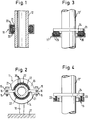
- the pipe clamp shown in Figs. 1 and 2 has a carrier ring 11 which e.g. consists of two half rings 13, 14 and encloses a tube 12.
- the half rings 13, 14 each have at their circumferential ends radially outwardly extending flanges 15 so that they can be screwed together by means of screws 16 to clamp the enclosed tube 12.
- a mandrel 18 is attached to one half ring 14 for fastening the pipe clamp to a building wall 17.
- the half rings 13, 14 of the pipe clamp are designed as a U-profile, in which a plurality of individual spring-elastic elements, preferably rubber balls 20 are arranged, which are held in a sheath formed as a mesh tube 21, part of which Rubber balls 20 protrudes from the U-profile.
- the rubber balls 20 held by the grid tubes 21 form two strands 22 which enclose the tube 12 in an approximately semicircular shape.
- a single line of sound insulation can be provided which completely surrounds the pipe.
- rubber balls 20 instead of the rubber balls 20, other bodies made of rubber or a resilient plastic can also be provided as resilient elements, e.g. are designed as cubes, stars, angles or the like.
- the holding and sound insulation properties can be suitably designed depending on the given requirements.
- FIG. 3 shows a pipe clamp serving as a downpipe support, the support ring 11 'of which is designed as an open U-profile in the axial direction. Rubber balls 20 held in a mesh tube 21 are inserted into this U-profile, with some of the rubber balls 20 projecting upward from the U-shaped carrier ring 11 '.
- a support flange 24 is provided, which rests on the rubber balls 20, so that the downpipe 12' is supported by the support flange 24 'in a manner not shown attached to a building part support ring 11'.
- a pipe clamp is shown, in the U-shaped support ring 11 compression springs 23 are used as sound insulation, which are supported on the one hand on a support flange 24 and on the other hand on the support ring 11.
- the holding and soundproofing properties can be designed as best as possible in accordance with the respective requirements.
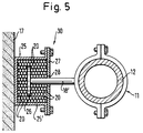
- the pipe clamp shown in FIG. 5 has a carrier ring 11 which surrounds a pipe 12.
- a support arrangement 30 with a support rod 18 ' is provided on the support ring 11 and carries a holding and damping plate 26 serving as an anchor part at its end facing away from the support ring 11.
- the anchor part can be flat or have another suitable shape if this is required for special fastening or damping conditions.
- the damping plate 26 provided on the support rod 18 is arranged together with its adjacent end section in a housing pot 25 'of the housing 25, which is covered by a cover 27 with an opening 28 through which the support rod 18' extends without contact.
- the cover 27 is screwed to the housing pot 25 'in such a way that the resilient elements arranged in the interior of the housing 25, in particular rubber balls 20, are compressed to produce a pretension.
- the housing 25 is fastened to it in a manner not shown, for example anchored.
- the rubber balls 20 arranged in the housing 25, which completely surround the damping plate 26 and the end section of the support rod 18 'located in the housing 25, are so closely packed that they support the support rod 18' and the damping plate 26 in the housing in order to be supported by the carrier ring 11 enclosed pipe 12 to be securely attached to the building wall 17.
- spring-elastic elements made of rubber or plastic can be used, which have different spring-elastic properties and / or shape and / or size.
- the support rod 18' and the damping plate 26 can be securely kept out of engagement with the housing 25 or its cover 27, so that in particular sound vibrations from the tube 12 are transferred to the pipe clamp 11, cannot be transferred to the housing or its cover and thus cannot be transferred to the building wall 17.
Landscapes
- Engineering & Computer Science (AREA)
- General Engineering & Computer Science (AREA)
- Mechanical Engineering (AREA)
- Supports For Pipes And Cables (AREA)
- Vibration Prevention Devices (AREA)
- Clamps And Clips (AREA)
- Pipe Accessories (AREA)
- Mutual Connection Of Rods And Tubes (AREA)
Applications Claiming Priority (2)
| Application Number | Priority Date | Filing Date | Title |
|---|---|---|---|
| DE4107885 | 1991-03-12 | ||
| DE4107885A DE4107885A1 (de) | 1991-03-12 | 1991-03-12 | Rohrschelle, insbesondere fuer installationsrohre, fallrohre u. dgl. |
Publications (3)
| Publication Number | Publication Date |
|---|---|
| EP0508085A2 true EP0508085A2 (fr) | 1992-10-14 |
| EP0508085A3 EP0508085A3 (en) | 1993-01-20 |
| EP0508085B1 EP0508085B1 (fr) | 1996-07-24 |
Family
ID=6427049
Family Applications (1)
| Application Number | Title | Priority Date | Filing Date |
|---|---|---|---|
| EP92103376A Expired - Lifetime EP0508085B1 (fr) | 1991-03-12 | 1992-02-27 | Tuyau d'installation ou de descente avec collier pour tuyau |
Country Status (3)
| Country | Link |
|---|---|
| EP (1) | EP0508085B1 (fr) |
| AT (1) | ATE140778T1 (fr) |
| DE (1) | DE4107885A1 (fr) |
Cited By (11)
| Publication number | Priority date | Publication date | Assignee | Title |
|---|---|---|---|---|
| EP0582354A1 (fr) * | 1992-08-05 | 1994-02-09 | J. van Walraven B.V. | Méthode pour la fixation d'un conduit en position verticale sur un mur |
| NL9300521A (nl) * | 1993-03-23 | 1994-10-17 | Walraven J Van Bv | Werkwijze voor het in een vertikale positie bevestigen van een leiding aan een wand. |
| EP0620397A1 (fr) * | 1993-04-15 | 1994-10-19 | HILTI Aktiengesellschaft | Dispositif de support |
| FR2708705A1 (fr) * | 1993-08-05 | 1995-02-10 | Peugeot | Dispositif de montage d'un tube sur un support. |
| US5647564A (en) * | 1992-08-05 | 1997-07-15 | J. Van Walraven B.V. | Method for fastening a pipe in a vertical position to a wall |
| DE10014050C1 (de) * | 2000-03-23 | 2001-10-31 | Rehau Ag & Co | Vorrichtung zur Befestigung von Rohren |
| GB2389884A (en) * | 2002-06-19 | 2003-12-24 | Schlumberger Holdings | Flow line securing support |
| CN101235929B (zh) * | 2007-01-29 | 2010-10-27 | 三星电子株式会社 | 配管支撑装置及具有该装置的空调机 |
| DE202014008983U1 (de) | 2014-11-12 | 2014-12-09 | Poloplast Gmbh & Co Kg | Hochschalldämmende Rohrbefestigungsvorrichtung |
| DE102014215394B3 (de) * | 2014-08-05 | 2015-05-21 | Poloplast Gmbh & Co. Kg | Hochschalldämmende Rohrbefestigungsvorrichtung |
| EP2982896A1 (fr) | 2014-08-05 | 2016-02-10 | Poloplast GmbH & Co. KG | Dispositif de fixation de tube insonorisant |
Families Citing this family (4)
| Publication number | Priority date | Publication date | Assignee | Title |
|---|---|---|---|---|
| DE4228961C2 (de) * | 1992-08-31 | 1995-01-26 | Missel Gmbh & Co E | Rohrbefestigungsvorrichtung mit einer Fixier- und einer Stützschelle |
| DE19504790C2 (de) * | 1995-02-14 | 1997-03-20 | Heinz Georg Launhardt | Wärmedämmendes Halterungssystem für vertikale und horizontale Hochtemperatur-Rohrleitungen |
| CN113007447B (zh) * | 2021-02-22 | 2023-05-23 | 中国核动力研究设计院 | 一种核动力管道减振吊架 |
| CN113007450B (zh) * | 2021-02-22 | 2023-06-27 | 中国核动力研究设计院 | 一种载荷可调的核动力管道减振支架 |
Family Cites Families (4)
| Publication number | Priority date | Publication date | Assignee | Title |
|---|---|---|---|---|
| FR460287A (fr) * | 1913-07-12 | 1913-11-27 | Constant Wallart | Perfectionnements dans les colliers d'assemblage |
| US3606218A (en) * | 1969-03-21 | 1971-09-20 | Gen Dynamics Corp | Sound and vibration isolation support |
| US4046169A (en) * | 1975-07-09 | 1977-09-06 | The United States Of America As Represented By The United States Energy Research And Development Administration | Pipe support for use in a nuclear system |
| CH664430A5 (en) * | 1984-06-15 | 1988-02-29 | Geberit Ag | Half shell clamp for pipeline - has sliding grip on pipe via U=shaped clamping band |
-
1991
- 1991-03-12 DE DE4107885A patent/DE4107885A1/de not_active Withdrawn
-
1992
- 1992-02-27 EP EP92103376A patent/EP0508085B1/fr not_active Expired - Lifetime
- 1992-02-27 AT AT92103376T patent/ATE140778T1/de active
Cited By (15)
| Publication number | Priority date | Publication date | Assignee | Title |
|---|---|---|---|---|
| US5647564A (en) * | 1992-08-05 | 1997-07-15 | J. Van Walraven B.V. | Method for fastening a pipe in a vertical position to a wall |
| WO1994003750A1 (fr) * | 1992-08-05 | 1994-02-17 | J. Van Walraven B.V. | Procede pour fixer un tuyau en position verticale contre un mur |
| EP0582354A1 (fr) * | 1992-08-05 | 1994-02-09 | J. van Walraven B.V. | Méthode pour la fixation d'un conduit en position verticale sur un mur |
| NL9300521A (nl) * | 1993-03-23 | 1994-10-17 | Walraven J Van Bv | Werkwijze voor het in een vertikale positie bevestigen van een leiding aan een wand. |
| EP0620397A1 (fr) * | 1993-04-15 | 1994-10-19 | HILTI Aktiengesellschaft | Dispositif de support |
| EP0638756A1 (fr) * | 1993-08-05 | 1995-02-15 | Automobiles Peugeot | Dispositif de montage d'un tube sur un support |
| FR2708705A1 (fr) * | 1993-08-05 | 1995-02-10 | Peugeot | Dispositif de montage d'un tube sur un support. |
| DE10014050C1 (de) * | 2000-03-23 | 2001-10-31 | Rehau Ag & Co | Vorrichtung zur Befestigung von Rohren |
| GB2389884A (en) * | 2002-06-19 | 2003-12-24 | Schlumberger Holdings | Flow line securing support |
| GB2389884B (en) * | 2002-06-19 | 2004-08-11 | Schlumberger Holdings | Wellsite systems |
| CN101235929B (zh) * | 2007-01-29 | 2010-10-27 | 三星电子株式会社 | 配管支撑装置及具有该装置的空调机 |
| DE102014215394B3 (de) * | 2014-08-05 | 2015-05-21 | Poloplast Gmbh & Co. Kg | Hochschalldämmende Rohrbefestigungsvorrichtung |
| EP2982896A1 (fr) | 2014-08-05 | 2016-02-10 | Poloplast GmbH & Co. KG | Dispositif de fixation de tube insonorisant |
| EP2982895A1 (fr) | 2014-08-05 | 2016-02-10 | Poloplast GmbH & Co. KG | Dispositif de fixation de tube insonorisant |
| DE202014008983U1 (de) | 2014-11-12 | 2014-12-09 | Poloplast Gmbh & Co Kg | Hochschalldämmende Rohrbefestigungsvorrichtung |
Also Published As
| Publication number | Publication date |
|---|---|
| EP0508085B1 (fr) | 1996-07-24 |
| DE4107885A1 (de) | 1992-09-17 |
| ATE140778T1 (de) | 1996-08-15 |
| EP0508085A3 (en) | 1993-01-20 |
Similar Documents
| Publication | Publication Date | Title |
|---|---|---|
| EP0508085A2 (fr) | Tuyau d'installation ou de descente avec collier pour tuyau | |
| DE3321382A1 (de) | Einrichtung zur gelenkigen verbindung von rohrteilen bei abgasanlagen in kraftfahrzeugen | |
| DE3640919C2 (fr) | ||
| DE2211507C3 (de) | Schwingungsdämpfer für Freileitungen | |
| DE1096707B (de) | Schwingungsdaempfer | |
| EP2982895B1 (fr) | Dispositif de fixation de tube insonorisant | |
| DE102014215394B3 (de) | Hochschalldämmende Rohrbefestigungsvorrichtung | |
| DE3421326C2 (de) | Hochtemperaturrohrschelle | |
| DE9117006U1 (de) | Rohrschelle | |
| DE19944956C1 (de) | Vorrichtung zur Befestigung eines Schwingungsdämpfers an einem Freileitungsseil | |
| DE4110268C2 (de) | Abdichtelement für mit Kabeln belegte Kabelzüge | |
| DE3421095C2 (de) | Dämpfungshalterung, insbesondere für dynamischen Belastungen und beträchtlichen Temperaturschwankungen ausgesetzte dünnwandige Rohrleitungen | |
| DE2063097B1 (de) | Längsgeteilte Kabelmuffe mit Kabelabfangung | |
| DE10103384C2 (de) | Abgasleitung für Brenngeräte in Gebäuden | |
| DE8020931U1 (de) | Vorrichtung zur schalldaemmenden befestigung von rohrleitungen | |
| DE202014008983U1 (de) | Hochschalldämmende Rohrbefestigungsvorrichtung | |
| DE2847892A1 (de) | Kompensator fuer rohrleitungen | |
| EP1844482A1 (fr) | Transformateur toroidal | |
| EP0075884B1 (fr) | Electrode de blindage pour haute tension | |
| DE3832376C2 (fr) | ||
| CH441679A (de) | Federanker und seine Verwendung | |
| DE4113904A1 (de) | Kontaktelement fuer ein koaxialkabel und dose zum anschliessen des koaxialkabels | |
| DE3422479A1 (de) | Kombinierte leitung aus kunststoffrohren | |
| DE562859C (de) | Aus laengsverlaufenden Draehten bestehender Drahtmantel zur Aufnahme des Isolationsmaterials fuer zylindrische Koerper, insbesondere Rohre | |
| DE3531751A1 (de) | Flaechig vorgespannte isolierung fuer heissgasleitungen und -behaelter |
Legal Events
| Date | Code | Title | Description |
|---|---|---|---|
| PUAI | Public reference made under article 153(3) epc to a published international application that has entered the european phase |
Free format text: ORIGINAL CODE: 0009012 |
|
| AK | Designated contracting states |
Kind code of ref document: A2 Designated state(s): AT BE CH FR IT LI LU NL |
|
| PUAL | Search report despatched |
Free format text: ORIGINAL CODE: 0009013 |
|
| AK | Designated contracting states |
Kind code of ref document: A3 Designated state(s): AT BE CH FR IT LI LU NL |
|
| 17P | Request for examination filed |
Effective date: 19930308 |
|
| 17Q | First examination report despatched |
Effective date: 19940809 |
|
| GRAG | Despatch of communication of intention to grant |
Free format text: ORIGINAL CODE: EPIDOS AGRA |
|
| GRAH | Despatch of communication of intention to grant a patent |
Free format text: ORIGINAL CODE: EPIDOS IGRA |
|
| GRAH | Despatch of communication of intention to grant a patent |
Free format text: ORIGINAL CODE: EPIDOS IGRA |
|
| GRAA | (expected) grant |
Free format text: ORIGINAL CODE: 0009210 |
|
| ITF | It: translation for a ep patent filed | ||
| AK | Designated contracting states |
Kind code of ref document: B1 Designated state(s): AT BE CH FR IT LI LU NL |
|
| REF | Corresponds to: |
Ref document number: 140778 Country of ref document: AT Date of ref document: 19960815 Kind code of ref document: T |
|
| ET | Fr: translation filed | ||
| PG25 | Lapsed in a contracting state [announced via postgrant information from national office to epo] |
Ref country code: LU Free format text: LAPSE BECAUSE OF NON-PAYMENT OF DUE FEES Effective date: 19970228 |
|
| PLBE | No opposition filed within time limit |
Free format text: ORIGINAL CODE: 0009261 |
|
| STAA | Information on the status of an ep patent application or granted ep patent |
Free format text: STATUS: NO OPPOSITION FILED WITHIN TIME LIMIT |
|
| 26N | No opposition filed | ||
| PGFP | Annual fee paid to national office [announced via postgrant information from national office to epo] |
Ref country code: FR Payment date: 19980216 Year of fee payment: 7 |
|
| PGFP | Annual fee paid to national office [announced via postgrant information from national office to epo] |
Ref country code: AT Payment date: 19980219 Year of fee payment: 7 |
|
| PGFP | Annual fee paid to national office [announced via postgrant information from national office to epo] |
Ref country code: CH Payment date: 19980220 Year of fee payment: 7 Ref country code: BE Payment date: 19980220 Year of fee payment: 7 |
|
| PGFP | Annual fee paid to national office [announced via postgrant information from national office to epo] |
Ref country code: NL Payment date: 19980228 Year of fee payment: 7 |
|
| PG25 | Lapsed in a contracting state [announced via postgrant information from national office to epo] |
Ref country code: AT Free format text: LAPSE BECAUSE OF NON-PAYMENT OF DUE FEES Effective date: 19990227 |
|
| PG25 | Lapsed in a contracting state [announced via postgrant information from national office to epo] |
Ref country code: LI Free format text: LAPSE BECAUSE OF NON-PAYMENT OF DUE FEES Effective date: 19990228 Ref country code: CH Free format text: LAPSE BECAUSE OF NON-PAYMENT OF DUE FEES Effective date: 19990228 Ref country code: BE Free format text: LAPSE BECAUSE OF NON-PAYMENT OF DUE FEES Effective date: 19990228 |
|
| BERE | Be: lapsed |
Owner name: E. MISSEL G.M.B.H. & CO. Effective date: 19990228 |
|
| PG25 | Lapsed in a contracting state [announced via postgrant information from national office to epo] |
Ref country code: NL Free format text: LAPSE BECAUSE OF NON-PAYMENT OF DUE FEES Effective date: 19990901 |
|
| REG | Reference to a national code |
Ref country code: CH Ref legal event code: PL |
|
| PG25 | Lapsed in a contracting state [announced via postgrant information from national office to epo] |
Ref country code: FR Free format text: LAPSE BECAUSE OF NON-PAYMENT OF DUE FEES Effective date: 19991029 |
|
| REG | Reference to a national code |
Ref country code: FR Ref legal event code: ST |
|
| PG25 | Lapsed in a contracting state [announced via postgrant information from national office to epo] |
Ref country code: IT Free format text: LAPSE BECAUSE OF NON-PAYMENT OF DUE FEES Effective date: 20050227 |