EP0508302A2 - Système de lecture de disque laser - Google Patents
Système de lecture de disque laser Download PDFInfo
- Publication number
- EP0508302A2 EP0508302A2 EP92105652A EP92105652A EP0508302A2 EP 0508302 A2 EP0508302 A2 EP 0508302A2 EP 92105652 A EP92105652 A EP 92105652A EP 92105652 A EP92105652 A EP 92105652A EP 0508302 A2 EP0508302 A2 EP 0508302A2
- Authority
- EP
- European Patent Office
- Prior art keywords
- laser disc
- playback system
- control
- laser
- control interface
- Prior art date
- Legal status (The legal status is an assumption and is not a legal conclusion. Google has not performed a legal analysis and makes no representation as to the accuracy of the status listed.)
- Withdrawn
Links
Images

Classifications
-
- G—PHYSICS
- G06—COMPUTING OR CALCULATING; COUNTING
- G06F—ELECTRIC DIGITAL DATA PROCESSING
- G06F3/00—Input arrangements for transferring data to be processed into a form capable of being handled by the computer; Output arrangements for transferring data from processing unit to output unit, e.g. interface arrangements
- G06F3/06—Digital input from, or digital output to, record carriers, e.g. RAID, emulated record carriers or networked record carriers
- G06F3/0601—Interfaces specially adapted for storage systems
-
- G—PHYSICS
- G11—INFORMATION STORAGE
- G11B—INFORMATION STORAGE BASED ON RELATIVE MOVEMENT BETWEEN RECORD CARRIER AND TRANSDUCER
- G11B11/00—Recording on or reproducing from the same record carrier wherein for these two operations the methods are covered by different main groups of groups G11B3/00 - G11B7/00 or by different subgroups of group G11B9/00; Record carriers therefor
- G11B11/03—Recording on or reproducing from the same record carrier wherein for these two operations the methods are covered by different main groups of groups G11B3/00 - G11B7/00 or by different subgroups of group G11B9/00; Record carriers therefor using recording by deforming with non-mechanical means, e.g. laser, beam of particles
-
- G—PHYSICS
- G08—SIGNALLING
- G08C—TRANSMISSION SYSTEMS FOR MEASURED VALUES, CONTROL OR SIMILAR SIGNALS
- G08C23/00—Non-electrical signal transmission systems, e.g. optical systems
- G08C23/04—Non-electrical signal transmission systems, e.g. optical systems using light waves, e.g. infrared
-
- G—PHYSICS
- G11—INFORMATION STORAGE
- G11B—INFORMATION STORAGE BASED ON RELATIVE MOVEMENT BETWEEN RECORD CARRIER AND TRANSDUCER
- G11B27/00—Editing; Indexing; Addressing; Timing or synchronising; Monitoring; Measuring tape travel
- G11B27/10—Indexing; Addressing; Timing or synchronising; Measuring tape travel
- G11B27/102—Programmed access in sequence to addressed parts of tracks of operating record carriers
- G11B27/105—Programmed access in sequence to addressed parts of tracks of operating record carriers of operating discs
-
- G—PHYSICS
- G06—COMPUTING OR CALCULATING; COUNTING
- G06F—ELECTRIC DIGITAL DATA PROCESSING
- G06F3/00—Input arrangements for transferring data to be processed into a form capable of being handled by the computer; Output arrangements for transferring data from processing unit to output unit, e.g. interface arrangements
- G06F3/06—Digital input from, or digital output to, record carriers, e.g. RAID, emulated record carriers or networked record carriers
- G06F3/0601—Interfaces specially adapted for storage systems
- G06F3/0668—Interfaces specially adapted for storage systems adopting a particular infrastructure
- G06F3/0671—In-line storage system
- G06F3/0673—Single storage device
-
- G—PHYSICS
- G11—INFORMATION STORAGE
- G11B—INFORMATION STORAGE BASED ON RELATIVE MOVEMENT BETWEEN RECORD CARRIER AND TRANSDUCER
- G11B2220/00—Record carriers by type
- G11B2220/20—Disc-shaped record carriers
- G11B2220/25—Disc-shaped record carriers characterised in that the disc is based on a specific recording technology
- G11B2220/2537—Optical discs
- G11B2220/2545—CDs
-
- G—PHYSICS
- G11—INFORMATION STORAGE
- G11B—INFORMATION STORAGE BASED ON RELATIVE MOVEMENT BETWEEN RECORD CARRIER AND TRANSDUCER
- G11B2220/00—Record carriers by type
- G11B2220/20—Disc-shaped record carriers
- G11B2220/25—Disc-shaped record carriers characterised in that the disc is based on a specific recording technology
- G11B2220/2537—Optical discs
- G11B2220/2587—Laser Discs; Optical disc using analog recording
Definitions
- the present invention is a combination of a computer and a so-called laser disc player, which is equipped in connection with a laser disc containing software (game or work program), while the computer manipulates the process under the control of control software.
- a control interface is suitable for transmitting data or electrical impulses from plugs via the cable to the parallel port and vice versa.
- the computer is able to control image and data information from a laser disc player with internal data and control pulses and can display these together on a computer monitor or normal television.
- the graphic information required for the game is taken directly from the disc (laser disc) and transferred from the player to the monitor.
- the graphic information is previously applied to a special "Laser Disc” storage medium. This laser disc holds up to 40 gigabits of data per page or more. A normal floppy disk holds up to 40 megabits of data on two sides. This means that about 1000 times the storage capacity for games is available on the laser disc used here.
- the control software is a routine programmed in assembler, which sends control commands to the parallel interface of any computer due to external impulses (joystick, mouse keyboard).
- This control software is suitable for all computer systems based on the 68 000 and up (e.g. Commodore Amiga, Atari ST, IBM and compatible devices).
- the controlled interfaces are identical in all computer systems.
- the control interface on which the invention is based consists of three different parts. These are a commercially available component called RS 232 or a parallel interface connector, a commercially available component called a dipole jack connector and a commercially available two-core, shielded cable.
- the user connects the parallel interface of his computer via the cable and the jack plug to the so-called input (remote control) socket of his laser disc player.
- control software After switching on the computer, the control software is loaded. Then switch on the laser disc player and insert the laser disc with the actual game. Depending on the present level, you are prompted to use any input device (keyboard, mouse, joystick), which starts the game. During the game, the user has the option of influencing the game sequence loaded from the laser disc using his input device (joystick etc.).
- the graphic information (from the laser disc) changes depending on the actuation of the input device.
- the control software recognizes the movements of the input device and in turn transmits control impulses to the laser disc player via the interface. Depending on the course of the game, this searches for the next program-related graphic sequence and displays it on the computer monitor. There is also the possibility that the control program recognizes at which point (which graphic sequence) the laser beam is located. It is then an interactive interaction of all components.
- the system according to the invention makes it possible for the user of laser disc players to use games located on laser discs in connection with the computer system. So far, this benefit has not existed.
- system according to the invention enables the use of user programs (professional area) by means of the underlying control software on any computer system.
- CD-ROM systems from professional EDP technology only work with a special computer system (e.g. IBM compatible) and offer no other possible uses.
- the laser discs used are storage media for digital acoustic and audiovisual data. This medium is able to record up to 40 gigabits per page. A normal data storage that works on a normal, magnetic basis, e.g. Floppy disks are only able to store 40 megabits of data.
- the laser disc is based on a laser-optical principle. This means that it works like an audio compact disc (12 cm ⁇ ) on which tiny "holes" are made, which can be optically scanned by a laser. In contrast to audio compact discs, the laser discs have a diameter of 30 cm. Computer games are stored on the laser discs used here and can be played back by a laser disc player. This playback alone has no function.
- a laser disc player is a commercially available device that is suitable for playing audio compact discs, laser discs, feature films, CD videos (12 cm ⁇ ).
- the control interface is suitable for transmitting data or electrical impulses from the plug via the cable for playing and possibly vice versa.
- the laser disc itself is considered a digital sound storage medium.
- the Laser Disc Player as such is only suitable for playing audio CDs, CD videos and laser discs.
- the computer is identified by reference number 1. With the reference number 2 the laser disc player to be used. Both are connected by means of the control interface 3.
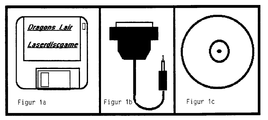
- the data carrier (diskette) for the control software is identified by the reference number 4, while the laser disc bears the reference number 5.
- Figure 1a shows the control software.
- Figure 1b the control interface with a parallel interface and Figure 1c the laser disc.
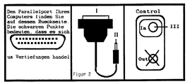
- Figure 2 the part of the interface labeled I ( Figure 2) must be inserted into the parallel port of the computer.
- the part of the interface labeled II is plugged into the control-in socket of the laser disc player (also called remote control) labeled III. Now both devices have to be switched on and the discs inserted.
- the retrieval of image and sound information stored on a laser disc with the aid of a laser disc player is controlled here by a computer with an interface and corresponding control software, the image information being displayed on a computer monitor and the sound information by suitable means in sound be implemented.
- the computer processor in this system is relieved of a lengthy graphic calculation, which is replaced by the control of the laser disc player.
- the data or electrical impulses are transmitted here via connectors and cable connections between the computer and the laser disc player.
- the computer is connected via the interface, parallel interfaces, to the control connections of the laser disc player using a cable equipped with appropriate plugs. This presupposes that the laser disc player has such control connections for a computer, which applies only to a few laser disc players on the market.
- a laser disc is a digital sound storage medium, but has so far been used in conjunction with a laser disc player only for playing audio CDs, CD videos and laser discs, but not as a data storage device for computers, so that the commercial players also are not equipped with a connector for a computer.
- connecting means between a computing unit or a computer and a laser disc player for a laser disc player system were created, which can be used for as many different commercially available laser disc players as possible.
- control interface of the computing unit as an infrared control interface and to establish the connection between the computing unit and a laser disc player with an infrared-based remote control receiver via the infrared control interface and the remote control receiver.
- this implementation of the interface enables wireless control of one or more laser disc players by means of a computing unit.
- the present invention makes it possible to set up the computer and laser disc player of a laser disc player system spatially separate from one another without the need for troublesome, complex cable connections. It is also advantageous that the use of the largely standard built-in remote control receiver of the laser disc player for data transmission between the computer and the player does not require any special design or equipment of the player.
- control pulses are modulated with a carrier frequency in order to avoid extraneous light influences during infrared transmission.
- control pulses that are present for example, in a first specific standard, such as the V 24 standard, can be converted into a second specific standard, e.g. into the TTL standard (transistor partial logic).
- the laser disc player system has means for varying the carrier frequency, for example for adapting to the remote control receivers of different laser disc players.
- the infrared control interface is equipped with light-emitting diodes (LED).
- a control interface of a laser disc playback system has to transmit data to the laser disc player much more and more frequently than a "normal" remote control and the peak currents of the light-emitting diodes have to be chosen to be quite high for safe transmission, it is advantageous to use a stabilized power supply instead of a battery supply.
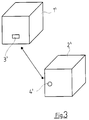
- FIG. 1 denotes a computing unit which has an infrared control interface 3'.
- a laser disc player 2 'with an infrared-based remote control receiver 4'.
- the data information transmission between the computing unit 1 'and the laser disc player 2' takes place wirelessly on an infrared basis via the infrared control interface 3 'and the remote control receiver 4', which is indicated by the arrow. Due to this form of data transmission, it is also possible to use one computing unit and an infrared interface to use several laser disc players, e.g. to control a turntable and a CD player.
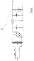
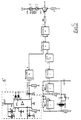
- FIG. 4 shows the circuit diagram of a stabilized power supply unit 5 'which can be used, for example, in connection with the light-emitting diodes of an infrared control interface.
- the components identified by the reference numerals and their operating parameters are listed following the description of the figures.
- a secure transmission of data via the infrared control interface requires the light-emitting diodes to be operated with increased current.
- the control interface according to the invention is transmitted much more frequently in connection with a laser disc playback system than is normally done with manual remote control. For this reason, a stabilized power supply unit for power supply to the control interface is preferable to a battery supply.
- 6 denotes a converter circuit with which a control pulse signal in the V 24 standard, as used as standard in computer interfaces, is converted into a control pulse signal in the TTL standard.
- the rising edges provided by the computer are improved with the NAND-Schmitt trigger designated as IC3.
- This switching element also performs various necessary inversions of the signal.
- the IC3 also serves to modulate the 2 MHz signal generated with an inverter IC4 and the signal divided with a variable frequency divider IC5 with the control signal. This technique is used to avoid the influence of extraneous light during infrared transmission.
- the transistor T1 amplifies the drive current for the two infrared light-emitting diodes D2 and D3.
- the other switching elements shown and designated in this circuit are also specified in the listing at the end of the description of the figures.
Landscapes
- Physics & Mathematics (AREA)
- Engineering & Computer Science (AREA)
- General Physics & Mathematics (AREA)
- Theoretical Computer Science (AREA)
- Optics & Photonics (AREA)
- Human Computer Interaction (AREA)
- General Engineering & Computer Science (AREA)
- Optical Recording Or Reproduction (AREA)
Applications Claiming Priority (4)
| Application Number | Priority Date | Filing Date | Title |
|---|---|---|---|
| DE9104433U DE9104433U1 (de) | 1991-04-12 | 1991-04-12 | Laser Disc Abspielsystem |
| DE9104433U | 1991-04-12 | ||
| DE9113596U DE9113596U1 (de) | 1991-10-31 | 1991-10-31 | Laser-Disc-Abspielsystem |
| DE9113596U | 1991-10-31 |
Publications (2)
| Publication Number | Publication Date |
|---|---|
| EP0508302A2 true EP0508302A2 (fr) | 1992-10-14 |
| EP0508302A3 EP0508302A3 (en) | 1995-03-01 |
Family
ID=25958064
Family Applications (1)
| Application Number | Title | Priority Date | Filing Date |
|---|---|---|---|
| EP92105652A Withdrawn EP0508302A3 (en) | 1991-04-12 | 1992-04-02 | Laser disk playback system |
Country Status (3)
| Country | Link |
|---|---|
| EP (1) | EP0508302A3 (fr) |
| JP (1) | JPH06187773A (fr) |
| KR (1) | KR920020432A (fr) |
Cited By (2)
| Publication number | Priority date | Publication date | Assignee | Title |
|---|---|---|---|---|
| EP0886277A3 (fr) * | 1997-06-20 | 2000-07-12 | Pioneer Electronic Corporation | Appareil de reproduction d'information |
| EP0853272A3 (fr) * | 1997-01-14 | 2000-08-02 | Mitsumi Electric Company Ltd. | Dispositif de stockage, dispositif de stockage/reproduction, et dispositifs de reproduction |
Family Cites Families (2)
| Publication number | Priority date | Publication date | Assignee | Title |
|---|---|---|---|---|
| JPH0322259A (ja) * | 1989-03-22 | 1991-01-30 | Seiko Epson Corp | 小型データ表示・再生装置 |
| JPH078060B2 (ja) * | 1989-03-28 | 1995-01-30 | 松下電器産業株式会社 | リモコン操作型電子機器制御システム |
-
1992
- 1992-04-02 EP EP92105652A patent/EP0508302A3/de not_active Withdrawn
- 1992-04-11 KR KR1019920006073A patent/KR920020432A/ko not_active Withdrawn
- 1992-04-13 JP JP4092750A patent/JPH06187773A/ja active Pending
Cited By (3)
| Publication number | Priority date | Publication date | Assignee | Title |
|---|---|---|---|---|
| EP0853272A3 (fr) * | 1997-01-14 | 2000-08-02 | Mitsumi Electric Company Ltd. | Dispositif de stockage, dispositif de stockage/reproduction, et dispositifs de reproduction |
| EP1452954A1 (fr) * | 1997-01-14 | 2004-09-01 | Mitsumi Electric Company Ltd. | Dispositif de stockage, dispositif de stockage/reproduction ,et dispositif de reproduction |
| EP0886277A3 (fr) * | 1997-06-20 | 2000-07-12 | Pioneer Electronic Corporation | Appareil de reproduction d'information |
Also Published As
| Publication number | Publication date |
|---|---|
| KR920020432A (ko) | 1992-11-21 |
| JPH06187773A (ja) | 1994-07-08 |
| EP0508302A3 (en) | 1995-03-01 |
Similar Documents
| Publication | Publication Date | Title |
|---|---|---|
| DE69635921T2 (de) | Fernsteuergerät eines Audiosystems | |
| DE3144014A1 (de) | "fernsehkamera und fernsteuerbares videosignal-aufzeichnungs/wiedergabegeraet" | |
| DE3210893C2 (de) | Geräteanordnung mit einem Fernsehempfangsgerät und einem Videdoaufnahme- und/oder -wiedergabegerät | |
| DE69227154T2 (de) | Optisches Informationsaufzeichnungs- und -wiedergabegerät | |
| DE29812256U1 (de) | Externes Verbindungs-Interface für periphere Vorrichtungen für Computer | |
| DE10353846A1 (de) | Verfahren zur Vorbereitung von für die Durchführung von medizinischen oder chirurgischen Eingriffen bestimmten Geräten | |
| DE212007000062U1 (de) | System zum Steuern von Videoauswahl und Wiedergabe in einem tragbaren Medienabspieler | |
| DE69829110T2 (de) | Verfahren zur beschreibung der benutzerschnittstellenmerkmale und funktionalität von av/c-geräten | |
| DE2123546B2 (de) | Magnetbandgerät zur Wiedergabe von auf ein Magnetband in beiden Bandlaufrichtungen aufgezeichneten Signalen | |
| DE3731505C2 (fr) | ||
| DE69601502T2 (de) | Elektronenrechner mit optischer platte | |
| EP0508302A2 (fr) | Système de lecture de disque laser | |
| DE2015538A1 (de) | Aufnahme- und Wiedergabegerät insbesondere für die Elektrokardiographie | |
| DE10100845A1 (de) | Schnittstelle zur Erzeugung von Prozeß- und Koordinationseingaben | |
| DE9113596U1 (de) | Laser-Disc-Abspielsystem | |
| DE3535715C2 (fr) | ||
| DE69417593T2 (de) | Vorrichtung und Verfahren zur Auswahl von Signalleitungen zur Verbindung mit einer Mehrzahl von Audio-Videogeräten | |
| DE3303011C2 (de) | Gerätesatz der Unterhaltungselektronik aus unterschiedlichen Gerätebausteinen | |
| DE4328010C2 (de) | Vorrichtung für die Aufzeichnung, Wiedergabe und Bearbeitung von Bild- und Tonsignalen | |
| DE9104433U1 (de) | Laser Disc Abspielsystem | |
| DE3438907A1 (de) | Schaltgeraet fuer videosignale | |
| DE2658397C3 (de) | Schaltungsanordnung zur Wiedergabe von auf einem Aufzeichnungsträger, insbesondere einem magnetischen Aufzeichnungsträger gespeicherten Informationen | |
| DE3909844C1 (fr) | ||
| DE102004010341A1 (de) | Abdeckungskonstruktion | |
| EP0412354A2 (fr) | Système interactif vidéo |
Legal Events
| Date | Code | Title | Description |
|---|---|---|---|
| PUAI | Public reference made under article 153(3) epc to a published international application that has entered the european phase |
Free format text: ORIGINAL CODE: 0009012 |
|
| AK | Designated contracting states |
Kind code of ref document: A2 Designated state(s): AT BE CH DE DK ES FR GB GR IT LI LU MC NL PT SE |
|
| PUAL | Search report despatched |
Free format text: ORIGINAL CODE: 0009013 |
|
| AK | Designated contracting states |
Kind code of ref document: A3 Designated state(s): AT BE CH DE DK ES FR GB GR IT LI LU MC NL PT SE |
|
| RIN1 | Information on inventor provided before grant (corrected) |
Inventor name: NEUEN, DIRK Inventor name: SELB, MICHAEL |
|
| STAA | Information on the status of an ep patent application or granted ep patent |
Free format text: STATUS: THE APPLICATION IS DEEMED TO BE WITHDRAWN |
|
| 18D | Application deemed to be withdrawn |
Effective date: 19950902 |