EP0508308A2 - Verfahren und Vorrichtung zur Beurteilung von automatischen Herstellungsmöglichkeiten - Google Patents
Verfahren und Vorrichtung zur Beurteilung von automatischen Herstellungsmöglichkeiten Download PDFInfo
- Publication number
- EP0508308A2 EP0508308A2 EP92105701A EP92105701A EP0508308A2 EP 0508308 A2 EP0508308 A2 EP 0508308A2 EP 92105701 A EP92105701 A EP 92105701A EP 92105701 A EP92105701 A EP 92105701A EP 0508308 A2 EP0508308 A2 EP 0508308A2
- Authority
- EP
- European Patent Office
- Prior art keywords
- product
- evaluation
- manufacturability evaluation
- parts
- manufacturability
- Prior art date
- Legal status (The legal status is an assumption and is not a legal conclusion. Google has not performed a legal analysis and makes no representation as to the accuracy of the status listed.)
- Granted
Links
Images




Classifications
-
- G—PHYSICS
- G05—CONTROLLING; REGULATING
- G05B—CONTROL OR REGULATING SYSTEMS IN GENERAL; FUNCTIONAL ELEMENTS OF SUCH SYSTEMS; MONITORING OR TESTING ARRANGEMENTS FOR SUCH SYSTEMS OR ELEMENTS
- G05B19/00—Program-control systems
- G05B19/02—Program-control systems electric
- G05B19/18—Numerical control [NC], i.e. automatically operating machines, in particular machine tools, e.g. in a manufacturing environment, so as to execute positioning, movement or co-ordinated operations by means of program data in numerical form
- G05B19/4097—Numerical control [NC], i.e. automatically operating machines, in particular machine tools, e.g. in a manufacturing environment, so as to execute positioning, movement or co-ordinated operations by means of program data in numerical form characterised by using design data to control NC machines, e.g. CAD/CAM
-
- G—PHYSICS
- G05—CONTROLLING; REGULATING
- G05B—CONTROL OR REGULATING SYSTEMS IN GENERAL; FUNCTIONAL ELEMENTS OF SUCH SYSTEMS; MONITORING OR TESTING ARRANGEMENTS FOR SUCH SYSTEMS OR ELEMENTS
- G05B19/00—Program-control systems
- G05B19/02—Program-control systems electric
- G05B19/418—Total factory control, i.e. centrally controlling a plurality of machines, e.g. direct or distributed numerical control [DNC], flexible manufacturing systems [FMS], integrated manufacturing systems [IMS] or computer integrated manufacturing [CIM]
- G05B19/41865—Total factory control, i.e. centrally controlling a plurality of machines, e.g. direct or distributed numerical control [DNC], flexible manufacturing systems [FMS], integrated manufacturing systems [IMS] or computer integrated manufacturing [CIM] characterised by job scheduling, process planning, material flow
-
- G—PHYSICS
- G05—CONTROLLING; REGULATING
- G05B—CONTROL OR REGULATING SYSTEMS IN GENERAL; FUNCTIONAL ELEMENTS OF SUCH SYSTEMS; MONITORING OR TESTING ARRANGEMENTS FOR SUCH SYSTEMS OR ELEMENTS
- G05B2219/00—Program-control systems
- G05B2219/30—Nc systems
- G05B2219/31—From computer integrated manufacturing till monitoring
- G05B2219/31065—Disassembly evaluation
-
- G—PHYSICS
- G05—CONTROLLING; REGULATING
- G05B—CONTROL OR REGULATING SYSTEMS IN GENERAL; FUNCTIONAL ELEMENTS OF SUCH SYSTEMS; MONITORING OR TESTING ARRANGEMENTS FOR SUCH SYSTEMS OR ELEMENTS
- G05B2219/00—Program-control systems
- G05B2219/30—Nc systems
- G05B2219/32—Operator till task planning
- G05B2219/32234—Maintenance planning
-
- G—PHYSICS
- G05—CONTROLLING; REGULATING
- G05B—CONTROL OR REGULATING SYSTEMS IN GENERAL; FUNCTIONAL ELEMENTS OF SUCH SYSTEMS; MONITORING OR TESTING ARRANGEMENTS FOR SUCH SYSTEMS OR ELEMENTS
- G05B2219/00—Program-control systems
- G05B2219/30—Nc systems
- G05B2219/35—Nc in input of data, input till input file format
- G05B2219/35028—Adapt design as function of manufacturing merits, features, for manufacturing, DFM
-
- G—PHYSICS
- G05—CONTROLLING; REGULATING
- G05B—CONTROL OR REGULATING SYSTEMS IN GENERAL; FUNCTIONAL ELEMENTS OF SUCH SYSTEMS; MONITORING OR TESTING ARRANGEMENTS FOR SUCH SYSTEMS OR ELEMENTS
- G05B2219/00—Program-control systems
- G05B2219/30—Nc systems
- G05B2219/35—Nc in input of data, input till input file format
- G05B2219/35193—Manufacturability
-
- G—PHYSICS
- G05—CONTROLLING; REGULATING
- G05B—CONTROL OR REGULATING SYSTEMS IN GENERAL; FUNCTIONAL ELEMENTS OF SUCH SYSTEMS; MONITORING OR TESTING ARRANGEMENTS FOR SUCH SYSTEMS OR ELEMENTS
- G05B2219/00—Program-control systems
- G05B2219/30—Nc systems
- G05B2219/35—Nc in input of data, input till input file format
- G05B2219/35199—Processability
-
- G—PHYSICS
- G05—CONTROLLING; REGULATING
- G05B—CONTROL OR REGULATING SYSTEMS IN GENERAL; FUNCTIONAL ELEMENTS OF SUCH SYSTEMS; MONITORING OR TESTING ARRANGEMENTS FOR SUCH SYSTEMS OR ELEMENTS
- G05B2219/00—Program-control systems
- G05B2219/30—Nc systems
- G05B2219/35—Nc in input of data, input till input file format
- G05B2219/35212—Estimating a cost associated with each operation, amount of time, target cost
-
- G—PHYSICS
- G05—CONTROLLING; REGULATING
- G05B—CONTROL OR REGULATING SYSTEMS IN GENERAL; FUNCTIONAL ELEMENTS OF SUCH SYSTEMS; MONITORING OR TESTING ARRANGEMENTS FOR SUCH SYSTEMS OR ELEMENTS
- G05B2219/00—Program-control systems
- G05B2219/30—Nc systems
- G05B2219/50—Machine tool, machine tool null till machine tool work handling
- G05B2219/50397—Two conveyors transporting together a workpiece to station
-
- Y—GENERAL TAGGING OF NEW TECHNOLOGICAL DEVELOPMENTS; GENERAL TAGGING OF CROSS-SECTIONAL TECHNOLOGIES SPANNING OVER SEVERAL SECTIONS OF THE IPC; TECHNICAL SUBJECTS COVERED BY FORMER USPC CROSS-REFERENCE ART COLLECTIONS [XRACs] AND DIGESTS
- Y02—TECHNOLOGIES OR APPLICATIONS FOR MITIGATION OR ADAPTATION AGAINST CLIMATE CHANGE
- Y02P—CLIMATE CHANGE MITIGATION TECHNOLOGIES IN THE PRODUCTION OR PROCESSING OF GOODS
- Y02P90/00—Enabling technologies with a potential contribution to greenhouse gas [GHG] emissions mitigation
- Y02P90/02—Total factory control, e.g. smart factories, flexible manufacturing systems [FMS] or integrated manufacturing systems [IMS]
Definitions
- the present invention is directed to improvement of manufacturability of an article or product and relates to a method of automatically and quantitatively evaluating whether a designed structure of a product is easy to manufacture and more particularly whether it is easy to assemble and process on the basis of design information generated by using a computer-aided design system (hereinafter also referred to as the CAD in abbreviation) and an automatic manufacturability evaluation system for carrying out the method.
- CAD computer-aided design system
- a product of concern has a structure easy to manufacture
- various methods For evaluating whether a product of concern has a structure easy to manufacture, there are known various methods.
- the design review method the manufacturability (i.e. ease of manufacture) of a product is determined by those skilled in the design, production and other fields on the basis of their empirical knowledges or experiences, wherein a portion or an area to be improved, if any, are pointed out by them. This method is widely adopted.
- a second evaluation method also adopted generally, a process planning for an article or product is created on the basis of a design drawing, whereon estimated assembling cost and time are arithmetically determined, and by taking into account the calculated values, the expert engineer skilled in manufacturing the product makes decision as to favorableness or satisfactoriness of the designed structure.
- a part attaching process is analytically divided into several ten process elements, which are then imparted with respective evaluation scores in dependence on the degrees of ease or difficulty of carrying out the process elements.
- a process required for attaching a part is represented by possible combinations of the process elements, whereon assemblability (i.e. degree of ease of assembling) as a whole is evaluated or those process elements which makes difficult the part attachment are eliminated.
- alignnability, positionability, chuckability, attachability and other items of parts are allocated with scores determined intuitively or empirically for representing degrees of ease or difficulty of aligning, positioning, chucking, attaching and so of the part, whereon assemblability as a whole is evaluated on the basic of a sum of the abovementioned scores or those items which provide difficulty in assembling are exclued.
- a fifth method there may be mentioned an assemblability evaluation method and a processability evaluation method disclosed in an extra issue "Meka Sekkei Jutzu (Mechanical Design Engineering), Series III" of "Nikkei Mechanical", pp. 191-199. This fifth method is concerned with an evaluation of a product assemblability on the basis of quantitative indexes related to operation costs expected to be involved.
- the first mentioned prior art evaluation method i.e. design review method
- the first mentioned prior art evaluation method is of qualitative nature rather than quantitative and is disadvantageous in that not a little difficulty is encountered in expressing objectively and quantitatively to what extent the structure of a product under evaluation is favorable or unfavorable (satisfactory or dissatisfactory) or how effective an improvement attempted will be.
- this method suffers from a problem that it can be carried out only by those having sufficient skillfulness in the design and process engineering.
- the second mentioned prior art evaluation method which is based on the estimated cost and time expected to be involved in the process or working
- the cost and time can certainly be estimated for a product as a whole or for every individual part or for some of parts constituting the product.
- the third prior art evaluation method (which is based on the evaluation score and index) certainly permits a time-sparing evaluation without need for rich experience.
- relation between the evaluation index and the cost and time involved in the processing is indefinite and that the result of evaluation is difficult to verify because of lacking of definite and concrete presentation of the engineering standards for determining the relation between the evaluation index and the expenditure.
- the fourth method is also disadvantageous in that any concrete engineering standards are inavailable for establishing relation between the evaluation index and the assembling cost, making it difficult or impossible to decide if a high evaluation score leads to a low cost or if a low score leads to a high cost. Additionally, a large number of items to be evaluated renders the evaluation process burdensome. In this manner, the fourth method is limited in the applicability. Furthermore, because the evaluation is impossible before the design has been completed, the fourth method is not suited for designing a product having a structure of high assemblability or parts of high attachability, to further disadvantage.
- the fifth method is carried out by using a system of such arrangement as shown schematically in Fig. 1 of the accompanying drawings.
- an evaluator 10 reads out information required for evaluation from a drawing 11, a sample or the like and inputs the information to a manufacturability evaluation system 14 by means of a keyboard 13, whereon the evaluation is performed by the system 14. Subsequently, the evaluator 10 makes decision on the basis of the result of evaluation outputted from the system 14 through the printer 15 as to whether the manufacturing process of concern is satisfactory or dissatisfactory with the aid of a facility 16. Next, the evaluator 10 improves the design, if it is necessary, whereon design improvement information, if any, is fed back to a CAD processing system 17.
- the present invention provides manufacturability evaluation method and system capable of determining a most desirable manufacturing process on the basis of product design information read out from a storage unit and including at least shape information of parts constituting a product to be manufactured by estimating at least one of manufacturing processes for manufacturing the product on the basis of the design information read out, determining arithmetically indexes representing manufacturabilites (degrees of ease of manufacture) for each of the estimated manufacturing processes, and determining the most desirable one of the manufacturing processes on the basis of the indexes.
- an automatic manufacturability evaluation method for automatically evaluating manufacturability of a product to be manufactured, which method comprises a step of reading product design information concerning parts constituting a product to be manufactured from a storage unit in which the information is previously stored, a manufacturing process estimating step for estimating at least a process for manufacturing the product on the basis of the product design information read out from the storage unit, and a manufacturability evaluation index calculation step of calculating a manufacturability evaluation index indicating a degree of ease of manufacturing the product (i.e. manufacturability thereof) by the estimated process.
- an automatic manufacturability evaluation system for evaluating manufacturability of a product to be manufactured in an automated manner, which system comprises a storage unit for storing previously product design information concerning parts constituting a product to be manufactured, a product design information read unit for reading the product design information of parts constituting a product of concern from the storage unit by inputting information concerning the parts, a manufacturing process estimating unit for estimating at least a process of manufacturing the product on the basis of the product design information read out from the storage unit, and a manufacturability evaluation index calculation unit for calculating a manufacturability evaluation index indicating a degree of ease of manufacturing the product by the estimated process.
- the product design information includes part identifying information such as names of parts constituting a product and attribute information concerning attributes of the parts such as shapes, sizes and the like, while the estimated manufacturing process or method usually includes at least one of a product assembling method, a part attaching sequence and a processing method.
- the present invention can be carried out in the modes mentioned below.
- a preferred embodiment of the manufacturability evaluation method according to the invention may include steps mentioned below.
- Fig. 2 is a block diagram showing a general arrangement of an automatic evaluation system according to an embodiment of the invention.
- a CAD (Computer-Aided Design) processing system 21 includes a CAD database 22 which is adapted to store drawing data derived from design drawings.
- drawing data it is intended to mean data or information concerning parts or constituents of a product or article depicted on a drawing and contains information of part names, geometrical information concering shapes and sizes or dimensions of the parts, attribute information concerning materials of the parts and surface states thereof such as roughness, processed surface state and others, information concerning methods of joining the parts and others.
- drawing data including the information mentioned above are stored in the CAD database 22 for all of the parts on a part-by-part basis.
- An automatic manufacturability evaluation system 30 for evaluating automatically the ease of manufacturing (i.e. manufacturability) of a given product is supplied with the relevant drawing data from the CAD database 22 and part purchase price information from a purchase price database 17 which stores data or information concerning purchase prices of individual parts, to thereby automatically evaluate quantitatively ease of assembling a product (hereinafter referred to as assemblability), ease of attaching of parts (hereinafter referred to as attachability), ease of processing thereof (hereinafter referred to as processability) and the like, wherein results of the evaluation are displayed on a display unit 32 and/or outputted to a printer 33 and/or stored in an evaluation information database 31.
- the drawing data stored in the CAD database 22 and the purchase price data stored in the purchase price database 17 will collectively be referred to as the product design information.
- Figs. 3A and 3B are views for illustrating an example of the drawing data stored in the CAD database 17 in an assumed case in which a block 2 is to be tightly attached or secured to a base 1 by means of an eyebolt 3.
- the drawing data concerning the base 1 may include, for example, information of the part identification number of "1", part quantity of "1", geometrical information of the part such as "cylindrical column having a diameter of 20 cm and a length of 10 cm", surface roughness information, coordinate information concerning the position at which the part or base 1 is to be located in a finished product, coordinate information concerning the position of a threaded bore formed in the base 1 and others as well as the attribute information concerning the material or the like of the base 1.
- the drawing data of the block 2 and the eyebolt 3 may be of similar contents.
- an evaluation information database 30 incorporated in the automatic manufacturability evaluation system 20 there are stored for each of basic elements which are involved in attaching a part and/or assembling a product, a symbol representing the basic element, a basic elimination score allocated thereto, a symbol of a supplementary element provided in correspondence to the basic element and a supplementary coefficient imparted thereto together with an evaluation score of the part attachability and/or product assemblability, real value of cost involved in actual manufacturing of the product and others, as will be described in more detail later on.
- Fig. 4 is a flow chart for illustrating a flow of processings in the automatic manufacturability evaluation.
- a step 111 the drawing data exemplified by those illustrated in Fig. 3A are read out from the CAD database 22 for all the parts to be subject to the evaluation by using as a key the part name or the part ID number.
- the outlet of the data fetching step 111 branches to a plurality of processing flows which includes a processability evaluation processing flow shown at a top row in Fig. 4, the assemblability evaluation processing flow shown at an intermediate row and an inspection susceptibility (ease-of-inspection) evaluation processing flow shown at a bottom row.
- step 112 shown in Fig. 4 decision is made as to whether all the information concerning the parts to be attached and subjected to the evaluation has been fetched in the step 111 and at the same time it is decided what sorts of the information is to be processed. At that time, if the information required for evaluation is insufficient, a corresponding message is issued to thereby cause the user to load additional design information or to input interactively the requisite information for the evaluation.
- step 113 the part attaching or assembling sequence which is considered reasonable is established. In this conjunction, let's assume, by way of example only, that three parts 1, 2 and 3 are to be assembled into a product.
- the assembling sequence reduction rules such as exemplified by those illustrated in Fig. 5 may be stored as knowledges of so-called production rules, as is conventionally adopted in the field of the artificial intelligence technology, wherein the rules are referred to for eliminating or excluding the assembling sequences which contradict the rules in respect to the conditions concerning the properties of the constituent parts, relations to the other part upon joining and the like. As a result of this, only a limited number of the assembling sequences which are to undergo the evaluation are selectively determined in a step 113 shown in Fig. 4.
- each of the assembling sequences is automatically evaluated by examining the processes or operations involved in attaching the parts on a part-by-part basis in such a manner as illustrated in Fig. 7.
- advantage is taken of the fact that a part attaching procedure is essentially equivalent to the reversal of a corresponding part detaching procedure. More specifically, in the case of the example illustrated in Fig.
- step 115 basic element data (basic elimination score) both concerning the assemblability evaluation and supplementary element data (supplementary coefficient) are read out from an evaluation information database 31 for each of the attachment methods decreased in number through the process described above, whereon attachability evaluation index is calculated for each of the attachment processes. The evaluation method to this end will be described later on. Subsequently, in a step 116, the attachmenmt process having the highest attachability evaluation index value as calculated is decided to be the optimal attachment process.
- the processability evaluation there is no room for the concept of the assembling sequence to play a role. Except for this, the processability evaluation can be effectuated similarly to the assemblability evaluation, as is illustrated in Fig. 4 at the top row. More specifically, there is selected one of the basic elements for the processability evaluation such as shown in Fig. 2 of U.S. Patent Application Serial No. 726,997 mentioned in the cross-reference which bears the greatest similarity to the drawing data derived from the drawing 11 (Fig. 2). Since the basic elements for the processability evaluation are determined on the basis of the geometrical factors or shapes of the parts, automatic extraction of the basic elements can easily be performed on the basis of the part shape data contained in the drawing data.
- the supplementary elements for the processability evaluation can easily be determined automatically on the basis of the attribute information contained in the drawing data and can be expressed in such a manner as is illustrated in Fig. 3 of aforementioned U.S. Patent Application Serial No. 726,997. Consequently, the processability evaluation index can equally be determined automatically by the method disclosed in the abovementioned U.S. Patent Application.
- a step 118 all the evaluation indexes including the assemblability evaluation index, the processability evaluation index, the inspection-susceptibility index are synthesized to thereby determine a synthetic evaluation index, whereon an overall cost is calculated on the basis of the synthetic evaluation index and the purchase price data of the parts subjected to the evaluation and stored in the purchase price database, the results of which are displayed on the display unit 32 and/or outputted to an output unit 33.
- the manufacturability evaluation system is equipped with the purchase price database 17, as shown in Fig. 4.
- the purchase price database 17 includes not only the estimated work costs such as involved in the processing or machining and the assembling but also the part purchase prices, delivery period, etc.. This in turn means that the manufacturability evaluation can be made synthetically, providing a benefit which the conventional evaluation system can not enjoy.
- the purchase price data is read out from the database 17 for determining the overall cost at a step 118. It should however be appreciated that in place of using the database 17, such arrangement may equally be adopted in which the evaluation system computer issues a query concerning the purchase prices to a system installed in a part purchase division, wherein the data supplied from the latter is utilized as the purchase price data.
- Fig. 10 is a block diagram showing, by way of example, a general arrangement of a computer system for realizing the automatic assemblability evaluation system and the automatic manufacturability evaluation system.
- the automatic evaluations according to the invention can be carried out by using a general-purpose type computer system in this manner, it is also possible to carry out the different evaluation processings by using dedicated microcomputers or hardware, respectively. Referring to Fig.
- the evaluation computer system comprises as major components an arithmetic unit 1 for performing arithmetic operations or calculations, a storage unit 2 for storing programs, a variety of basic data as well as input data and the results of the arithmetic operations, a display unit 3 for displaying data inputted manually or transferred from the CAD processor system and the results of the arithmetic operations, an input unit 4 such as a keyboard, mouse or the like for enabling data input by operator, a printer 5 for outputting the results of the arithmetic operations and others.
- an arithmetic unit 1 for performing arithmetic operations or calculations
- a storage unit 2 for storing programs, a variety of basic data as well as input data and the results of the arithmetic operations
- a display unit 3 for displaying data inputted manually or transferred from the CAD processor system and the results of the arithmetic operations
- an input unit 4 such as a keyboard, mouse or the like for enabling data input by operator
- a printer 5 for outputting the
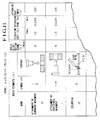
- Fig. 11 is a view for illustrating a variety of basic data stored in the storage unit 2.
- basic data there may be mentioned basic elements and basic element symbols X representing the basic elements, basic elimination scores ⁇ x assigned to the basic elements, respectively, supplementary elements (which will be described hereinafter by reference to Fig. 12) and symbols ⁇ representing these supplementary elements and supplementary coefficients ⁇ imparted to these supplementary elements and others.
- the assemblability evaluation software is so programmed as to execute the processings included in the evaluation process (described hereinafter by reference to Fig. 13), which processings include input processing of the basic element data X i and identifiers N i thereof on a part-by-part basis, calculation for correcting the basic elimination score ⁇ ij with the supplementary coefficient ⁇ for each of the part attaching sequences j, calculation of the part assemblability evaluation score a E i based on the sum of the corrected elimination scores, calculations of the product assemblability evaluation score E, the assembling time (i.e. time taken for the assembling) T and the assembling cost (i.e.
- the attaching operation which is most easy to carry out is taken as a standard element X0, and the basic elimination score ⁇ x which is assigned to the standard element X0 is set to "0" (zero).
- the elimination scores ⁇ x to be assigned thereto are increased in dependence on the degrees of difficulty in effectuating these other basic elements when compared with that of the standard element X0.
- the basic elimination scores ⁇ x given to the other basic elements X than standard element X0 are determined to increase from "0" (zero) as the attachment costs C x of the other basic elements X increase beyond the attachment cost C xo of the standard element X0 under the same production conditions as that for the standard element X0.
- the attachment cost (i.e. cost involved in attaching or assembling a part) C x may be replaced by the attachment time T x or the index I x thereof or a product of the attachment time T x and a shop allotment rate A.
- the supplementary elements ⁇ and supplementary coefficient ⁇ will be considered by reference to Fig. 12.
- the supplementary elements ⁇ there may be mentioned material m , size l , finishing accuracy a and others.
- n represents an integer greater than or equal to 1
- supplementary standards m o , l o , a o , ...) are defined for the supplementary elements, respectively.
- These supplementary elements can be derived from the information available from the drawing or product or the part and represent items which affect the ease of attachment of the part (i.e. the part attachability) in addition to the basic elements described above.
- the supplementary coefficient ⁇ is a supplementary index representing the degree of influence exerted to the part attachability by the supplementary element.
- This relation can be expressed by where the suffix "X mean" affixed to the right-hand bracket in the above expression indicates that the supplementary coefficient ⁇ n indicates a mean value of the values obtained from the calculations for a plurality of the basic elements X.
- the attachment costs C x ⁇ n , C x ⁇ o may be replaced by the attachment times T x ⁇ n , T x ⁇ o or indexes I x ⁇ n , I x ⁇ o thereof or products of T x ⁇ n , T x ⁇ o and the shop allotment ratio A substantially to the same effect, as described hereinbefore in conjunction with the basic elimination score ⁇ .
- FIG. 11 there are shown in a first column some exemplary basic elements X resulting from classification of attachment operations (i.e. operations for attaching parts).
- a first example 10 of the basic element is attachment of a part by moving it downwardly (i.e. by downward movement)
- a second example 11 is attachment of a part by horizontal movement thereof
- a third example 12 is a soldering operation.
- attachment operations i.e. operations for attaching parts.
- FIG. 11 A first example 10 of the basic element is attachment of a part by moving it downwardly (i.e. by downward movement)
- a second example 11 is attachment of a part by horizontal movement thereof
- a third example 12 is a soldering operation.
- Other types attachment operations are conceivable as the basic elements X, although not shown.
- These basic elements can be extracted from the drawing information and/or design information available from the CAD system while inputting interactively some information, if necessary, and represent distinctively the movements, joining or mounting methods of parts upon attachments thereof in manufacturing
- Illustrated in a third column of the table shown in Fig. 11 are contents of the basic elements, whose number may be in a range of several to several tens. As the number of the basic elements increases, the accuracy of analysis and evaluation is enhanced, although difficulty increases more or less in making use of the basic elements in the evaluation. On the contrary, as the number of the basic elements decreases, the evaluation process can certainly be simplified, correspondingly. However, accuracy of the evaluation is degraded correspondingly.
- the number of the basic element should preferably be on the order of twenty, while in the case of the automatic evaluation based on the information available from the CAD system, the evaluation processing can be performed without encountering any noticeable difficulty in most of practical applications even when the number of the basic elements is greater than twenty.
- the basic element symbols allocated to the basic elements, respectively, are shown in a second column of the table of Fig. 11.
- the basic element symbols are so determined that the corresponding basic elements can associatively be understood from the symbols.
- the downward movement can be represented by a downward arrow " ⁇ " with the soldering being represented by "S”.
- a fourth column of the table shown in Fig. 11 there are entered exemplary values of the basic elimination scores assigned to the basic elements, respectively.
- the downward movement which is most easy to carry out for attachment of a part is taken as the standard for the basic element and assigned with the basic elimination score of "0" (zero), while for the other basic elements, the basic elimination scores ⁇ x increases as the difficulty in attaching or mounting the corresponding parts increases when compared with that of the standard basic element.
- the basic elimination scores ⁇ x for the other basic elements than the standard are so determined as to increase as the corresponding part attachment time T x , for example, increases under the same production conditions, e.g. same number of products, same production means and same operation mode, i.e. manual or automatic, as is shown in a sixth column of the table of Fig. 11.
- the basic elimination score ⁇ x may be determined on the basis of the attachment cost instead of the attachment time.
- the elimination score can be determined on the basis of the length of the path along which the robot is moved in place of the part attachment time.
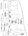
- Fig. 12 shows examples of the supplementary element.
- the items of the supplementary elements there may be mentioned sizes of parts, attachment accuracies and others.
- These supplementary elements can basically be extracted only from the drawing data or the design information supplied from the CAD processing system (with inputting interactively additional information as required) and represent in terms of numerical values the items which exert influence to the part attachability in addition to the basic elements. It should however be added that the supplementary elements are insusceptible to change in dependence on the production conditions such as the number of products and the production means.
- the method for correction there may be mentioned a first method of calculating the part elimination score by multiplying the basic elimination score ⁇ x with the supplementary coefficient ⁇ mentioned above for each part attachment operation, a second method of multiplying a value resulting from subtraction of a total sum of elimination scores for the parts ( ⁇ xi ) from the standard score point (100 points) with the supplementary coefficients and any other methods.
- the part attachability evaluation score E i calculated is to be so determined that it always assumes a high value whennever the part is easy to attach or whennever the attachment time taken for attaching the part is short.
- the part attachability evaluation score E i is an index which represents the quality of attachability of the part (i.e. ease of attachment of part).
- the part attachability evaluation score E i of a part can be calculated on the basis of a sum of the basic elimination scores ⁇ x each of which in turn is determined on the basis of the attachment time T x for each of the basic elements.
- the product assemblability evaluation score E represents the degree of ease of assembling a product as a whole in contrast to the part attachability evaluation score E i which is an index representing the degree of ease of attaching a part i of the product.
- Fig. 13 is a flow chart for illustrating processings executed by the computer system shown in Fig. 10.
- the attachment operation of a part to be evaluated is represented by the symbols of the basic element and the supplementary element.
- the element symbol representing the operation most approximately or closely are selectively determined by the operator.
- the element symbol representing the vertical movement may be selected.
- the symbol representing the soldering may be selected. The selection of these element symbols is effected manually in the case of the semi-automatic evaluation system. However, in the case of the CAD-linked automatic system, these element symbols can be determined automatically.
- a step 2 shown in Fig. 13 the symbols of the basic elements and the supplementary elements are manually inputted on a part-by-part basis through the keyboard.
- these element symbols are automatically inputted to the evaluation system by a corresponding load program.
- the part elimination score m e i is subtracted from the standard score (of 100 points), the result of which is determined as the part attachability evaluation score a E i .
- a E i 100 - m e i (9)
- a representative mean value of the part attachability evaluation scores is determined for all the parts constituting a product of concern and defined as the product assemblability evaluation score E.
- a sum ⁇ a E i of the part attachability evaluation scores a E i of the individual parts is divided by a total number N of all the parts.
- the assemblability evaluation score E determined for the product as a whole in this manner can be considered to indicate that the product has a same degree of assemblability (i.e. degree of ease of assembling) as an assembly or aggregation of the parts having the part attachability evaluation score of "E" on an average.
- the product assembling time T or cost C (i.e. time or cost required for assembling the product) is estimated on the basis of the product assemblability evaluation score E and the number N of the parts in accordance with the expression (5) or (6).
- the computer calculates automatically all or desired one of the assemblability evaluation score, the assembling time and the assembling cost, the result of which can be displayed on the display unit and/or outputted through the printer when it is required.
- the result mentioned above can be displayed and/or printed out and/or stored in the storage unit.
- the data thus stored can be utilized for a process path scheduling for a robot (automatic generation of movement paths of the robot) required for assembling the product as designed or utilized for a manufacturing facility scheduling (e.g. as to how many machines or tools are required in what layout) as well.
- the symbols of the basic elements and the supplementary elements are assigned to individual keys of the keyboard, respectively, for facilitating the manual inputting or correction of result of the automatic analysis of the CAD-linked system.
- Figs. 14A and 14B examples of such keyboard are illustrated.
- the keys should preferably be assigned with the symbols such that the characters imprinted thereon can facilitate association with the symbols.
- the symbols of the basic elements for which the alphabetic letters are used as they are, as shown in Fig.
- keyboards may be assigned to the keys of the same alphabetic letters, respectively, while the basic elements for which other symbols than the alphabetic letters are used may preferably be assigned to the function keys.
- An example of such keyboard configuration is disclosed in U.S. Applications Serial Nos. 726,997 and 654,236 mentioned hereinbefore.
- a sheet known as an overlay sheet may be laid over the keyboard, and relevant symbols may be written on the sheet at locations close to the individual key so that the symbols of the basic elements assigned to the keys can immediately be understood.
- a list of the element symbols may be generated on a display screen of a CAD display unit, wherein the element symbol as desired may be selected by designating with a cursor by means of a pointing device or the like.
- the numerical data may well be inputted by using the ten-keys.
- the methods mentioned above may be adopted for correcting manually a result of the analysis performed by the system.
- Fig. 15 is a flow chart for illustrating a processing procedure of the product assemblability evaluation based on the basic elements and the supplementary elements.
- the parts to be evaluated and represented by combinations of the basic elements are the supplementary elements.
- a step 2 basic elements and supplementary elements are inputted to the computer system on a part-by-part basis.
- the processings in the steps 1 and 2 should preferably be executed automatically, they may be performed manually by operator.
- step 3 data inputted through the keyboard are displayed on the display unit.
- the basic elimination scores and the supplementary coefficients corresponding to the basic elements and the supplementary elements used for representing the part to be evaluated are read out from the evaluation information database 31.
- the basic elimination scores read out in the preceding step are corrected by the supplementary coefficients, whereon a sum of the results of the correction is defined as representing the part elimination score.
- a sum of the results of the correction is defined as representing the part elimination score.
- the part elimination score is subtracted from the standard score (usually a perfect score of 100 points), the result of which is defined as the part attachability evaluation score.
- the part attachability evaluation score thus calculated is stored in the database 31.
- step 7 it is checked whether or not the processings mentioned above have been performed for all the parts of concern. If the answer of this step 7 is negative (NO), the abovementioned processings are repeated until all the parts have undergone the processings.
- a mean value of the part attachability evaluation scores of all the parts constituting a product of concern is determined and corrected, if necessary, or alternatively a median value of the part attachability evaluation scores is arithmetically determined to be defined as the product assemblability evaluation score representing the assemblability (i.e. ease of assembling) of the product as a whole.
- the assembling time and/or assembling cost of the product of concern is estimated on the basis of the assemblability evaluation score of the product and the number of parts or alternatively the assemblability evaluation score, the number of constituent parts, assembling time and assembling cost of the similar product in accordance with the expression (5) and/or expression (6) mentioned hereinbefore. Additionally, data of other factors which may have influence to the assembling cost such as the number of products to be manufactured, shop cost per hour and the like may previously be inputted for correcting the calculated assembling cost.
- the product assemblability evaluation score is intrinsically a value which is related to the mean attachment cost of all the parts constituting the product. Accordingly, the product assembling cost can be determined on the basis of the mean part attachment cost and the number of the parts and by correcting the result in consideration of the number of products to be manufactured and the shop cost per hour. Parenthetically, the assembling time can be obtained by dividing the assembling cost with the shop cost per hour.
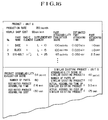
- Fig. 16 shows an example of data as outputted.
- the evaluation data are assumed to be independently outputted through the printer.
- all or a part of the output information may be displayed or printed on the drawing created by the CAD system.
- the assemblability evaluation scores are determined by adopting a low-point method of scoring (i.e. method of reducing or substracting the score) from the standard score of "100".
- a low-point method of scoring i.e. method of reducing or substracting the score
- various modifications of this scoring method are conceivable such as those exemplified by a method of determining the assemblability evaluation score by using the low-point method of scoring from the standard score of "0" (zero), method of determining the assemblability evaluation score according to a high-point method of scoring from the standard score of "0”, a method of determining the assemblability evaluation score by the high-point method on the basis of the standard score of "100” and others.
- the assemblability evaluation method described above is made use of. More specifically, in the assembling sequence generating step 113 shown in Fig. 4, the part attaching operations are classified into the basic elements related to the movements of the parts, as illustrated in Fig. 11, whereon the basic elements are arrayed in the sequenced order, starting from the smallest basic elimination score ⁇ ij such as exemplified by an orderly array of the first basic element of the downward movement (which is most simple), the second basic element of horizontal movement toward a mounted part and so forth.
- the parts i to be attached are assumed to be removed or detached through the movements reverse to those involved in the attachment in the abovementioned order, e.g. the upward movement firstly, the horizontal movement away from the mounted part secondly, and so forth, to thereby check whether the part to be attached interferes with the attached or mounted part.
- This check operation can be realized by making use of the part interference check function incorporated in the associated CAD system. When interference is observed, the relevant attaching movement is excluded. This process is executed sequentially until the basic element which does not interfere with the mounted part is found. In the case of the example illustrated in Fig. 17, the part 142 to be attached can be detached by moving that part 142 in the upward direction without interfering the mounted part.
- the basic element to be assigned to the part 142 is the movement represented by the symbol " ⁇ ".
- the elimination score of the basic element representing a single movement is greater than that of the basic element representing double movements (such as exemplified by " ⁇ " shown in Fig. 16)
- such algorithm should preferably be adopted that the attachment through the single movement is first checked.
- a step 116 the arithmetic attachability evaluation described hereinbefore is performed for all the attaching sequences determined through the procedure mentioned above. More specifically, in this step 116, movements of the parts required for attachment or mounting thereof which are suited for the attaching sequences generated in the step 113 are detected, while the attribute information stored in the CAD database 22 such as part joining condition, machining information or the like is read out, whereon the detected movements and information read out from the database 22 are compared with the basic elements determined through the attachability evaluation method to thereby determine automatically all the basic elements and supplementary elements as required for each of the parts to be attached.
- one or both of the attachability evaluation score and attachment cost for each of the parts and hence one or both of the assemblability evaluation score and the assembling cost are determined for each of the parts and the product as a whole, respectively.
- the assemblability evaluation scores calculated in the step 115 for all the possible attaching or assembling sequences are mutually compared to finally determine the assembling sequence having the highest evaluation score as the assembling sequence and method which is most rational and economical.
- results of the evaluations described above can also be made use of in generating automatically a facility control schedule and control information for a robot and machining tools.
- the evaluation of manufacturability of a product can be carried out in a fully-automated or semi-automated manner with the assemblability and the attachability of a product and parts can remarkably be improved, whereby high improvement can be achieved with respect to the efficiency and economy in the manufacture of products or articles.
- an automatic manufacturability evaluation method and system which can afford quantitative evaluation in a clearly understandable form for a product to be manufactured at the level of part attachment or in a subassembled or completely assembled state instantly at any time in the course of designing with a CAD system without need for any especial knowledge and experience.
- a CAD system without need for any especial knowledge and experience.
- economization can easily be accomplished.
- the designer himself or herself can evaluate and improve the design in the course of designing, whereby a high-quality design of a product improved in respect to the manufacturability can be created within a relatively short time.
- the rational part attaching sequence and attaching methods can be automatically established already at the stage of design, it is possible to estimate in precedence to production the number and types of production facilities and tools, which is very advantageous for planning the production schedule.
- the information of part attaching and assembling operations to be carried out by production machine or tool such as industrial robot is available at the stage of design, it is possible to generate numerical control data relatively easily and directly from the design information. In the case of machining operation, it is possible at the stage of design how to control a byte of a numerically controlled machining tool.
Landscapes
- Engineering & Computer Science (AREA)
- Manufacturing & Machinery (AREA)
- Physics & Mathematics (AREA)
- General Physics & Mathematics (AREA)
- Automation & Control Theory (AREA)
- General Engineering & Computer Science (AREA)
- Quality & Reliability (AREA)
- Human Computer Interaction (AREA)
- Management, Administration, Business Operations System, And Electronic Commerce (AREA)
- Automatic Assembly (AREA)
Priority Applications (1)
| Application Number | Priority Date | Filing Date | Title |
|---|---|---|---|
| EP97115530A EP0819996A3 (de) | 1991-04-04 | 1992-04-02 | Verfahren und Vorrichtung zur Beurteilung von automatischen Herstellungsmöglichkeiten |
Applications Claiming Priority (2)
| Application Number | Priority Date | Filing Date | Title |
|---|---|---|---|
| JP71488/91 | 1991-04-04 | ||
| JP7148891 | 1991-04-04 |
Related Child Applications (1)
| Application Number | Title | Priority Date | Filing Date |
|---|---|---|---|
| EP97115530A Division EP0819996A3 (de) | 1991-04-04 | 1992-04-02 | Verfahren und Vorrichtung zur Beurteilung von automatischen Herstellungsmöglichkeiten |
Publications (3)
| Publication Number | Publication Date |
|---|---|
| EP0508308A2 true EP0508308A2 (de) | 1992-10-14 |
| EP0508308A3 EP0508308A3 (de) | 1992-12-30 |
| EP0508308B1 EP0508308B1 (de) | 1998-03-18 |
Family
ID=13462096
Family Applications (2)
| Application Number | Title | Priority Date | Filing Date |
|---|---|---|---|
| EP92105701A Expired - Lifetime EP0508308B1 (de) | 1991-04-04 | 1992-04-02 | Verfahren und Vorrichtung zur Beurteilung von automatischen Herstellungsmöglichkeiten |
| EP97115530A Withdrawn EP0819996A3 (de) | 1991-04-04 | 1992-04-02 | Verfahren und Vorrichtung zur Beurteilung von automatischen Herstellungsmöglichkeiten |
Family Applications After (1)
| Application Number | Title | Priority Date | Filing Date |
|---|---|---|---|
| EP97115530A Withdrawn EP0819996A3 (de) | 1991-04-04 | 1992-04-02 | Verfahren und Vorrichtung zur Beurteilung von automatischen Herstellungsmöglichkeiten |
Country Status (2)
| Country | Link |
|---|---|
| EP (2) | EP0508308B1 (de) |
| DE (1) | DE69224764T2 (de) |
Cited By (12)
| Publication number | Priority date | Publication date | Assignee | Title |
|---|---|---|---|---|
| US5799293A (en) * | 1996-11-04 | 1998-08-25 | Ford Global Technologies, Inc. | Method for optimizing the design of a product using knowledge-based engineering techniques |
| US6535863B1 (en) | 2000-04-06 | 2003-03-18 | Ford Motor Company | Method for utilizing a knowledge-based system |
| US6598036B1 (en) | 2000-04-04 | 2003-07-22 | Ford Global Technologies, Llc | Method for serving engineering rules on a network through servlet and applet |
| US6741898B2 (en) | 2000-09-29 | 2004-05-25 | Ford Motor Company | Method of using neutral event file for manufacturing line analysis |
| US6748283B2 (en) | 2000-09-29 | 2004-06-08 | Ford Motor Company | Method of using neutral event specification file for manufacturing line analysis |
| WO2006103236A1 (en) * | 2005-03-29 | 2006-10-05 | Siemens Audiologische Technik Gmbh | Hearing aid impression buildability index computation tool |
| US7308327B2 (en) | 2006-05-12 | 2007-12-11 | Ford Motor Company | Method of application protocol monitoring for programmable logic controllers |
| US7346478B2 (en) | 2004-09-21 | 2008-03-18 | Ford Motor Company | Method of embedding tooling control data within mechanical fixture design to enable programmable logic control verification simulation |
| US7702491B2 (en) | 2000-09-29 | 2010-04-20 | Ford Global Technologies, Llc | Method of part flow model for programmable logic controller logical verification system |
| US20100185312A1 (en) * | 2009-01-20 | 2010-07-22 | Gm Global Technology Operations, Inc. | System for evaluating manufacturability of a casting design |
| US9335760B2 (en) | 2009-10-02 | 2016-05-10 | Apriori Technologies, Inc. | Template framework for automated process routing |
| US10466681B1 (en) | 2014-09-02 | 2019-11-05 | Machine Research Corporation | Systems and methods for machining knowledge reuse |
Families Citing this family (4)
| Publication number | Priority date | Publication date | Assignee | Title |
|---|---|---|---|---|
| GB9920560D0 (en) | 1999-08-31 | 1999-11-03 | British Aerospace | Feature based assembly |
| AU2001222364A1 (en) * | 2000-11-16 | 2002-05-27 | Metalunity B.V. | Apparatus and method for offering and trading material working operations and material working products |
| US10817526B2 (en) | 2014-07-16 | 2020-10-27 | Machine Research Corporation | Systems and methods for searching a machining knowledge database |
| CN105956227B (zh) * | 2016-04-19 | 2018-11-23 | 北京理工大学 | 一种Pro/E环境的可制造性评价规则定义方法 |
Family Cites Families (3)
| Publication number | Priority date | Publication date | Assignee | Title |
|---|---|---|---|---|
| US5109337A (en) * | 1987-10-28 | 1992-04-28 | Ibm Corporation | Conceptual design tool |
| US4931944A (en) * | 1988-05-27 | 1990-06-05 | General Motors Corporation | Method of optimizing a vehicle assembly line build sequence |
| JP3230813B2 (ja) * | 1990-07-11 | 2001-11-19 | 株式会社日立製作所 | 物品の複数作業種の作業容易性の総合評価方法およびその装置 |
-
1992
- 1992-04-02 EP EP92105701A patent/EP0508308B1/de not_active Expired - Lifetime
- 1992-04-02 DE DE69224764T patent/DE69224764T2/de not_active Expired - Fee Related
- 1992-04-02 EP EP97115530A patent/EP0819996A3/de not_active Withdrawn
Non-Patent Citations (6)
| Title |
|---|
| 9TH PROCEEDINGS OF NAT. COMP. GRAPHICS ASSOC. (NGGA) 1988 vol. 3, 1988, USA pages 55 - 109 P. VILLERS * |
| PROCEEDINGS 1990 IEEE INTERNATIONAL CONFERENCE ON ROBOTICS AND AUTOMATION May 1990, USA pages 1756 - 1762 B.R. DONALD & D.K. PAI * |
| PROCEEDINGS OF MANUFACTURING INTERNATIONAL 1990 vol. 1, March 1990, USA pages 213 - 218 U.P. KORDE ET AL * |
| ROBOTICS AND COMPUTER INTEGRATED MANUFACTURING vol. 4, no. 1-2, 1988, OXFORD GB pages 69 - 76 V.R. MILICIC & M. UROSEVIC * |
| SOVIET ENGINEERING RESEARCH vol. 3, no. 3, March 1983, GB pages 46 - 51 YU. M. SOLOMENTSEV & V.V. KUZMIN 'PRINCIPLES OF CONSTRUCTING AN AUTOMATED SYSTEM FOR ASSESSING THE MANUFACTURABILITY OF MECHANICAL COMPONENTS' * |
| TECHNISCHE RUNDSCHAU vol. 78, no. 45, November 1986, BERN CH pages 16-21,23,25 R. BÄSSLER & T. SCHMAUS * |
Cited By (14)
| Publication number | Priority date | Publication date | Assignee | Title |
|---|---|---|---|---|
| US5799293A (en) * | 1996-11-04 | 1998-08-25 | Ford Global Technologies, Inc. | Method for optimizing the design of a product using knowledge-based engineering techniques |
| US6598036B1 (en) | 2000-04-04 | 2003-07-22 | Ford Global Technologies, Llc | Method for serving engineering rules on a network through servlet and applet |
| US6535863B1 (en) | 2000-04-06 | 2003-03-18 | Ford Motor Company | Method for utilizing a knowledge-based system |
| US6741898B2 (en) | 2000-09-29 | 2004-05-25 | Ford Motor Company | Method of using neutral event file for manufacturing line analysis |
| US6748283B2 (en) | 2000-09-29 | 2004-06-08 | Ford Motor Company | Method of using neutral event specification file for manufacturing line analysis |
| US7702491B2 (en) | 2000-09-29 | 2010-04-20 | Ford Global Technologies, Llc | Method of part flow model for programmable logic controller logical verification system |
| US7346478B2 (en) | 2004-09-21 | 2008-03-18 | Ford Motor Company | Method of embedding tooling control data within mechanical fixture design to enable programmable logic control verification simulation |
| US8190280B2 (en) | 2005-03-29 | 2012-05-29 | Siemens Corporation | Hearing aid impression buildability index computation tool |
| WO2006103236A1 (en) * | 2005-03-29 | 2006-10-05 | Siemens Audiologische Technik Gmbh | Hearing aid impression buildability index computation tool |
| US7308327B2 (en) | 2006-05-12 | 2007-12-11 | Ford Motor Company | Method of application protocol monitoring for programmable logic controllers |
| US20100185312A1 (en) * | 2009-01-20 | 2010-07-22 | Gm Global Technology Operations, Inc. | System for evaluating manufacturability of a casting design |
| US8706283B2 (en) * | 2009-01-20 | 2014-04-22 | GM Global Technology Operations LLC | System for evaluating manufacturability of a casting design |
| US9335760B2 (en) | 2009-10-02 | 2016-05-10 | Apriori Technologies, Inc. | Template framework for automated process routing |
| US10466681B1 (en) | 2014-09-02 | 2019-11-05 | Machine Research Corporation | Systems and methods for machining knowledge reuse |
Also Published As
| Publication number | Publication date |
|---|---|
| EP0508308B1 (de) | 1998-03-18 |
| DE69224764D1 (de) | 1998-04-23 |
| EP0819996A2 (de) | 1998-01-21 |
| DE69224764T2 (de) | 1998-07-09 |
| EP0508308A3 (de) | 1992-12-30 |
| EP0819996A3 (de) | 1998-03-18 |
Similar Documents
| Publication | Publication Date | Title |
|---|---|---|
| US6223092B1 (en) | Automatic manufacturing evaluation method and system | |
| EP0508308B1 (de) | Verfahren und Vorrichtung zur Beurteilung von automatischen Herstellungsmöglichkeiten | |
| US20060129462A1 (en) | Automated planning and manufacturing systems | |
| JP2020095724A (ja) | 機械加工製品をカスタマイズするシステムおよび方法 | |
| US20020026392A1 (en) | Method and apparatus for estimating product cost | |
| JPH0664588B2 (ja) | 設計支援方法 | |
| US5907488A (en) | Method of evaluating easiness of works and processings performed on articles and evaluation apparatus | |
| US5303147A (en) | Computer aided planning method and system | |
| JP3024350B2 (ja) | 製造性自動評価方法およびシステム | |
| US20060129461A1 (en) | Data entry and system for automated order, design, and manufacture of ordered parts | |
| US5586022A (en) | Method of evaluating easiness of works and processings performed on articles and evaluation apparatus | |
| US20060129270A1 (en) | Processes and systems for creation of machine control for specialty machines requiring manual input | |
| CN120633465B (zh) | 一种航空发动机柔性产线仿真方法及系统 | |
| JPH05324778A (ja) | 製造設備設計装置 | |
| US6920364B2 (en) | Work assistance apparatus and memory medium for use therein | |
| EP0466098A2 (de) | Verfahren und Apparat zur Auswertung der Eignung eines Gegenstandes für eine feste Operation | |
| JPH0581291A (ja) | 製造ライン計画方法およびその装置 | |
| JP2000202746A (ja) | 製品部品表編集方法及びその装置 | |
| US20080104543A1 (en) | Guidance Apparatus, Method and Program of Analysis Work | |
| Stelmakh | Method and Automated System of Technological Preparation of Small-Scale Assembly Production in Instrumentation | |
| JPH10334151A (ja) | 不良率推定方法、不良率推定システムおよび記録媒体 | |
| Joseph et al. | Knowledge based process planning system for turned components | |
| Kotsyuba et al. | Automating MySQL database complexity estimation based on quantitative metrics | |
| JPH08234977A (ja) | ソフトウェアプロジェクトにおける多面的進捗管理方式 | |
| JPH0926998A (ja) | 製造所内の金属帯の品質関連情報の入手方法および装置 |
Legal Events
| Date | Code | Title | Description |
|---|---|---|---|
| PUAI | Public reference made under article 153(3) epc to a published international application that has entered the european phase |
Free format text: ORIGINAL CODE: 0009012 |
|
| 17P | Request for examination filed |
Effective date: 19920402 |
|
| AK | Designated contracting states |
Kind code of ref document: A2 Designated state(s): DE GB |
|
| PUAL | Search report despatched |
Free format text: ORIGINAL CODE: 0009013 |
|
| AK | Designated contracting states |
Kind code of ref document: A3 Designated state(s): DE GB |
|
| 17Q | First examination report despatched |
Effective date: 19940901 |
|
| GRAG | Despatch of communication of intention to grant |
Free format text: ORIGINAL CODE: EPIDOS AGRA |
|
| GRAG | Despatch of communication of intention to grant |
Free format text: ORIGINAL CODE: EPIDOS AGRA |
|
| GRAH | Despatch of communication of intention to grant a patent |
Free format text: ORIGINAL CODE: EPIDOS IGRA |
|
| GRAH | Despatch of communication of intention to grant a patent |
Free format text: ORIGINAL CODE: EPIDOS IGRA |
|
| GRAA | (expected) grant |
Free format text: ORIGINAL CODE: 0009210 |
|
| AK | Designated contracting states |
Kind code of ref document: B1 Designated state(s): DE GB |
|
| DX | Miscellaneous (deleted) | ||
| REF | Corresponds to: |
Ref document number: 69224764 Country of ref document: DE Date of ref document: 19980423 |
|
| PLBE | No opposition filed within time limit |
Free format text: ORIGINAL CODE: 0009261 |
|
| STAA | Information on the status of an ep patent application or granted ep patent |
Free format text: STATUS: NO OPPOSITION FILED WITHIN TIME LIMIT |
|
| 26N | No opposition filed | ||
| REG | Reference to a national code |
Ref country code: GB Ref legal event code: IF02 |
|
| PGFP | Annual fee paid to national office [announced via postgrant information from national office to epo] |
Ref country code: GB Payment date: 20040324 Year of fee payment: 13 |
|
| PGFP | Annual fee paid to national office [announced via postgrant information from national office to epo] |
Ref country code: DE Payment date: 20040608 Year of fee payment: 13 |
|
| PG25 | Lapsed in a contracting state [announced via postgrant information from national office to epo] |
Ref country code: GB Free format text: LAPSE BECAUSE OF NON-PAYMENT OF DUE FEES Effective date: 20050402 |
|
| PG25 | Lapsed in a contracting state [announced via postgrant information from national office to epo] |
Ref country code: DE Free format text: LAPSE BECAUSE OF NON-PAYMENT OF DUE FEES Effective date: 20051101 |
|
| GBPC | Gb: european patent ceased through non-payment of renewal fee |
Effective date: 20050402 |