EP0508331B1 - Element de fermeture en particulier pour colliers - Google Patents
Element de fermeture en particulier pour colliers Download PDFInfo
- Publication number
- EP0508331B1 EP0508331B1 EP92105848A EP92105848A EP0508331B1 EP 0508331 B1 EP0508331 B1 EP 0508331B1 EP 92105848 A EP92105848 A EP 92105848A EP 92105848 A EP92105848 A EP 92105848A EP 0508331 B1 EP0508331 B1 EP 0508331B1
- Authority
- EP
- European Patent Office
- Prior art keywords
- pin
- screw bolt
- locking
- connecting element
- screw
- Prior art date
- Legal status (The legal status is an assumption and is not a legal conclusion. Google has not performed a legal analysis and makes no representation as to the accuracy of the status listed.)
- Expired - Lifetime
Links
- 239000007787 solid Substances 0.000 claims description 4
- 238000010276 construction Methods 0.000 claims description 3
- 238000000034 method Methods 0.000 description 5
- 238000009434 installation Methods 0.000 description 2
- 238000004519 manufacturing process Methods 0.000 description 2
- 239000008186 active pharmaceutical agent Substances 0.000 description 1
- 230000001419 dependent effect Effects 0.000 description 1
- 230000002349 favourable effect Effects 0.000 description 1
- 238000003466 welding Methods 0.000 description 1
Images
Classifications
-
- F—MECHANICAL ENGINEERING; LIGHTING; HEATING; WEAPONS; BLASTING
- F16—ENGINEERING ELEMENTS AND UNITS; GENERAL MEASURES FOR PRODUCING AND MAINTAINING EFFECTIVE FUNCTIONING OF MACHINES OR INSTALLATIONS; THERMAL INSULATION IN GENERAL
- F16L—PIPES; JOINTS OR FITTINGS FOR PIPES; SUPPORTS FOR PIPES, CABLES OR PROTECTIVE TUBING; MEANS FOR THERMAL INSULATION IN GENERAL
- F16L3/00—Supports for pipes, cables or protective tubing, e.g. hangers, holders, clamps, cleats, clips, brackets
- F16L3/08—Supports for pipes, cables or protective tubing, e.g. hangers, holders, clamps, cleats, clips, brackets substantially surrounding the pipe, cable or protective tubing
- F16L3/12—Supports for pipes, cables or protective tubing, e.g. hangers, holders, clamps, cleats, clips, brackets substantially surrounding the pipe, cable or protective tubing comprising a member substantially surrounding the pipe, cable or protective tubing
- F16L3/137—Supports for pipes, cables or protective tubing, e.g. hangers, holders, clamps, cleats, clips, brackets substantially surrounding the pipe, cable or protective tubing comprising a member substantially surrounding the pipe, cable or protective tubing and consisting of a flexible band
-
- F—MECHANICAL ENGINEERING; LIGHTING; HEATING; WEAPONS; BLASTING
- F16—ENGINEERING ELEMENTS AND UNITS; GENERAL MEASURES FOR PRODUCING AND MAINTAINING EFFECTIVE FUNCTIONING OF MACHINES OR INSTALLATIONS; THERMAL INSULATION IN GENERAL
- F16L—PIPES; JOINTS OR FITTINGS FOR PIPES; SUPPORTS FOR PIPES, CABLES OR PROTECTIVE TUBING; MEANS FOR THERMAL INSULATION IN GENERAL
- F16L3/00—Supports for pipes, cables or protective tubing, e.g. hangers, holders, clamps, cleats, clips, brackets
- F16L3/08—Supports for pipes, cables or protective tubing, e.g. hangers, holders, clamps, cleats, clips, brackets substantially surrounding the pipe, cable or protective tubing
- F16L3/12—Supports for pipes, cables or protective tubing, e.g. hangers, holders, clamps, cleats, clips, brackets substantially surrounding the pipe, cable or protective tubing comprising a member substantially surrounding the pipe, cable or protective tubing
Definitions
- the invention relates to a connecting part with the features of the preamble of claim 1.
- connecting parts relate to clamps, by means of which pipes accommodated in them can be fixed.
- a screw bolt passes through two pins provided with recesses in the form of bores, which are wrapped by a clamp band. If the tube cannot be inserted laterally into the clamp, the screw bolt must be removed from the recesses and the elastic clamp band is pulled apart until the tube enters the opening between fits through the two opposite pegs, in order to be subsequently enclosed in the clamp by the clamp band. To close the clamp, the screw bolt is then inserted through the recesses in the pin and tightened with a suitable tool until the pipe is securely enclosed by the clamp.
- the screw bolt When the pipe is received, the screw bolt can remain in the recess of one of the two pins and is pivotably arranged there for a corresponding length compensation of the clamp depending on the diameter range of the pipe to be received by means of the assigned pin.
- the longitudinal adjustment is achieved by means of a threaded nut that can be screwed onto the screw bolt.
- the known connecting part can therefore only be fully opened when the threaded nut is removed and when the screw bolt is at least led out of the bore with its free end, so that opening and closing is difficult and takes a lot of time.
- a connecting part for connecting two ends which partially encloses a pin in the region of one end and which has a longitudinally adjustable, pivotable engaging part which engages in the U-shaped groove of a leg piece forming a recess, which is arranged at the other end of the connecting part and firmly connected thereto.
- the engaging part in the form of a screw bolt can be fixed in the leg piece by means of a sleeve-like nut for closing the closure part.
- a connecting part is known in which the two ends protrude outdoors in a web-like manner and essentially at right angles.
- the closure part is fixed, in particular when high closing forces are applied, the webs may bend and the connection part may become involuntarily detached.
- the closure part of DE-OS 33 46 423 contrary to the closure part according to DE-PS 35 22 497, already has a pivotable engagement part in the form of a screw bolt, which ensures that the connection can be released quickly; the swivel mechanism developed for this purpose, which includes one of the two webs, is complicated in construction and therefore expensive to manufacture.
- a connecting part is known, the ends of which are folded over to form angle pieces and connected to the remaining connecting part by means of a stitch.
- the elbows formed by the turning over are penetrated by a longitudinally adjustable engaging part in the form of a screw bolt.
- the engaging part has to be completely loosened, which is time-consuming.
- EP-A-0 286 561 discloses a connecting part of the same type, in which both pins are designed as hollow cylinders, the pin which is intended to be latched to the screw head of the screw bolt having a continuous longitudinal slot.
- the latching part in this sleeve-like pin consists of a circular recess which is enlarged relative to the groove and into which a widening of the screw bolt or the entire screw body which is provided for this purpose and with a diameter engages.
- the widening of the screw bolt is held within the pin by the undercut formed by the latching part and groove, with a support washer, which in the known solution is between the hexagon head and the widening is arranged, outside of the pin with it takes over the support.
- the screw head of the screw bolt with its support washer must be arranged outside the associated pin with the locking part, with the result that the known clamp builds up large in this area, which is disadvantageous in particular for cramped installation conditions for assembly . With large holding forces, the pin is deformed, particularly in the area of the latching part, so that failure cannot be ruled out.
- the invention has for its object to provide an improved connection part, which is inexpensive to manufacture and which allows a cheap force application when applying high holding forces without failure.
- a related object is achieved by a connecting part with the features of claim 1.
- the pin provided with the locking part is solid and that the locking part forms a flat contact surface due to the circular recess, which can be brought into direct contact with the facing surface of the underside of the screw head for the locking process, the screw head of the screw thread directly into the assigned pin, which saves installation space and allows high holding forces to be applied, since these can be introduced without failure into the solid pin via the flat contact surface within the locking part.
- connecting part is the subject of the dependent claims.
- the connecting part according to the invention is particularly advantageously suitable for opening and closing clamps, as are shown, for example, in the applicant's unpublished DE-OS 41 11 359.4.
- the connecting part according to the invention is used to open and close an articulated band bracket clamp according to DE 41 11 359.4, which is described there in detail, so that its construction is not dealt with in more detail at this point.
- this clamp has a clamp band which is essentially circular and delimits a receiving space 12 in which a pipe (not shown) can be fixed in its position.
- the clamp band 10 has two mutually opposite ends 14 and 16, each partially a pin. 18 or 20 enclose and preferably the pin 18.20 hold axially immovable in their position in the clamp band 10.
- the clamp band 10 wrapped around the two pins 18, 20 is connected to the rest of the clamp band 10 by spot welding, forming the eyes for the pins 18, 20 to be received.
- a screw bolt is provided as the engaging part 22, which has a thread 24 at one end and a screw head 26 at its other end, which has a hexagon socket recess for the engagement of a tool.
- a threaded nut 28 can be screwed onto the thread 24 of the screw bolt 22.
- the engagement part 22 can be adjusted lengthwise by means of this threaded nut 28.
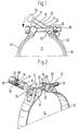
- the clamp band 10 is longitudinally divided and the pin 20, which is designed as a hollow cylinder, has a continuous recess 30 which is oval in shape and which is penetrated by the screw bolt 22.
- the pin 20 has 30 projections (not shown) in the region of its recess, which cooperate with a widening 32 of the clamp band in such a way that the pin 20 is held by the looped part of the clamp band 10 so that it can pivot about 180 °. Thanks to this pivotability, the pin 20, as shown in particular in FIG. 1, can be pivoted to a limited extent and, after the screw bolt 22 has been removed, can also be removed from the clamp band 10 by hand.
- the second pin 18 shown as a separate part in FIG. 2 is solid and has a continuous groove 34 transversely to its longitudinal direction, which opens into a latching part 36 for latching with the engaging part 22.
- the two opposite side walls of the groove 34 are flat and open into a semicircular groove bottom, the diameter of which is adapted to the diameter of the bolt 22.
- the locking part 36 is formed from a circular recess 38 in the pin 18, the diameter of which corresponds to the diameter of the screw head 26, the recess 38 forming an undercut 40 with the groove 34, into which the screw head 26 can be snapped.
- the cylindrical pin 18 has a position in the clamp band 10 that the groove 34 with its opening running transversely to the longitudinal direction of the pin 18 faces the screw bolt 22.
- the locking part 36 thus forms a flat contact surface which can be brought into contact with the surface of the underside of the screw head 26 facing it for the locking process.
- the screw bolt 22 is screwed on by means of an Allen key, the threaded nut 28 remaining in abutment with the part of the clamp band 10 wound around it with two of its surfaces which are intended for the engagement of a tool.
- the screw bolt 22 is screwed on until the screw head 26 disengages from the undercut 40 of the locking part 36. Then the screw bolt 22 can be pivoted upward against the arrow direction shown in FIG. 1 by means of the pin 20.
- the screw bolt 22 can be pushed completely through the recess 30 of the pin 20 until the screw head 26 comes into contact with the deflected part of the clamp band 10.
- the elastic clamp band can then be widened further to accommodate or remove a tube (not shown) that is already in the receiving space 12.
- the screw bolt 22 is returned to its position shown in FIG. 1 above, the two clamp ends 14, 16 being bent toward one another.
- the screw head 26 comes into contact with the pin 18. Due to the inherent tension of the clamp band 10 that wants to open, the screw head 26 is pulled into the latching part 36 and the screw head 26 comes into contact with the undercut 40.
- the screw bolt 22 is then tightened via the hexagon socket in the screw head 26, the threaded nut 28 with two of its Tool engagement surfaces in contact with the clamp band 10 and thus serves as a lock nut.
- the clamp can be provided with profile rubber pieces 42 which are U-shaped in cross section. If the mutually facing ends of the two profiled rubber pieces 42 comprise the lower part of the two pins 18, 20 (not shown), they can thus be held in their axial position within the looped area of the clamp band 10.
- the closure part according to the invention need not be limited to the use for clamps. For example, chain links or flat, band-shaped, link-like parts could also be connected to one another.
Landscapes
- Engineering & Computer Science (AREA)
- General Engineering & Computer Science (AREA)
- Mechanical Engineering (AREA)
- Clamps And Clips (AREA)
- Insertion Pins And Rivets (AREA)
- Supports For Pipes And Cables (AREA)
- Snaps, Bayonet Connections, Set Pins, And Snap Rings (AREA)
- Load-Engaging Elements For Cranes (AREA)
- Pivots And Pivotal Connections (AREA)
- Sheet Holders (AREA)
- Braking Arrangements (AREA)
Claims (4)
- Elément d'assemblage enfermant, dans la plage de ses deux extrémités (14, 16), au moins partiellement, un tourillon (18, 20) et formant, avec un élément de fermeture monté entre les deux extrémités (14, 16) comprenant un élément d'insertion (22) pivotant réglable en longueur en forme de boulon fileté introduit dans les alésages (30, 34) des deux tourillons, l'alésage de l'un des deux tourillons étant réalisé sous la forme d'une rainure (34) présentant un cliquet (36) pour fixer la tête (26) du boulon fileté pivotant par encliquetage dans la rainure constituant une contre-dépouille (40) avec le cliquet, le tourillon (18) muni du cliquet (36) étant massif et ledit cliquet étant réalisé, avec sa contre-dépouille, par un creux circulaire (38) aménagé dans ledit tourillon, le diamètre dudit creux correspondant au diamètre de la tête (26) du boulon fileté, caractérisé en ce que le cliquet (36) forme une surface d'appui plane (50) pouvant être mise en appui contre la face inférieure juxtaposée de la tête (26) du boulon fileté pour réaliser l'encliquetage.
- Elément d'assemblage selon la revendication 1, caractérisé en ce que le boulon fileté (22) comprend un filetage (24) pouvant être introduit à travers au moins un tourillon (20) et sur lequel peut être vissé un écrou (28), ce dernier pouvant être appuyé sur l'un des éléments d'assemblage (10).
- Elément d'assemblage selon l'une quelconque des revendications 1 ou 2, caractérisé en ce que le tourillon (18) comprenant le cliquet (36) est relié par adhérence à l'élément d'assemblage (10), tandis que l'autre tourillon (20), peut pivoter par rapport à ce dernier.
- Elément d'assemblage selon l'une quelconque des revendications 1 à 3, caractérisé en ce que l'élément d'assemblage (10) correspondant est réalisé sous la forme d'un ruban ou d'une chaîne ou d'un élément de ces derniers.
Applications Claiming Priority (4)
| Application Number | Priority Date | Filing Date | Title |
|---|---|---|---|
| DE19914111359 DE4111359A1 (de) | 1991-04-09 | 1991-04-09 | Gelenkband-konsolenschelle |
| DE4111359 | 1991-04-09 | ||
| DE9110844U | 1991-09-02 | ||
| DE9110844U DE9110844U1 (de) | 1991-04-09 | 1991-09-02 | Verschlußteil, insbesondere für Schellen |
Publications (3)
| Publication Number | Publication Date |
|---|---|
| EP0508331A2 EP0508331A2 (fr) | 1992-10-14 |
| EP0508331A3 EP0508331A3 (en) | 1993-06-30 |
| EP0508331B1 true EP0508331B1 (fr) | 1996-03-13 |
Family
ID=25902635
Family Applications (2)
| Application Number | Title | Priority Date | Filing Date |
|---|---|---|---|
| EP92101731A Expired - Lifetime EP0508050B1 (fr) | 1991-04-09 | 1992-02-03 | Collier du support avec charniere |
| EP92105848A Expired - Lifetime EP0508331B1 (fr) | 1991-04-09 | 1992-04-04 | Element de fermeture en particulier pour colliers |
Family Applications Before (1)
| Application Number | Title | Priority Date | Filing Date |
|---|---|---|---|
| EP92101731A Expired - Lifetime EP0508050B1 (fr) | 1991-04-09 | 1992-02-03 | Collier du support avec charniere |
Country Status (4)
| Country | Link |
|---|---|
| US (1) | US5474269A (fr) |
| EP (2) | EP0508050B1 (fr) |
| AT (2) | ATE129329T1 (fr) |
| DE (3) | DE9110844U1 (fr) |
Cited By (1)
| Publication number | Priority date | Publication date | Assignee | Title |
|---|---|---|---|---|
| DE29608259U1 (de) * | 1996-05-07 | 1996-08-01 | HYDAC Befestigungstechnik GmbH, 66280 Sulzbach | Konsolenschelle |
Families Citing this family (38)
| Publication number | Priority date | Publication date | Assignee | Title |
|---|---|---|---|---|
| GB2281584A (en) * | 1993-09-02 | 1995-03-08 | Michael Wyn Harold | A pipeline strap having a protective covering |
| DE9417491U1 (de) * | 1994-10-31 | 1994-12-15 | Hydac Befestigungstechnik GmbH, 66125 Saarbrücken | Spannbandunterlage |
| DE19518309C1 (de) * | 1995-05-18 | 1996-03-14 | Hydac Befestigungstechnik Gmbh | Schelle mit Halte- und Stützband |
| IT243432Y1 (it) * | 1997-08-07 | 2002-03-04 | Irca Spa | Dispositivo perfezionato per serraggio di resistenze o dicarter anulare |
| USD412972S (en) | 1997-09-22 | 1999-08-17 | Flex-Cable, Inc. | Clasp with a locking pin for a welding cable or fluid hose |
| DE19744397A1 (de) * | 1997-10-08 | 1999-04-15 | Oetiker Hans Maschinen | Vorrichtung zur Befestigung von Schlauchschellen |
| US5913467A (en) * | 1997-12-17 | 1999-06-22 | Berg; Daniel T. | Mounting system for securing a pair of main scuba tanks to a back plate |
| US6047930A (en) * | 1998-07-29 | 2000-04-11 | Hendrix Wire & Cable, Inc. | Aerial cable retainer with fulcrum point |
| US6565452B2 (en) * | 1999-11-01 | 2003-05-20 | Callaway Golf Company | Multiple material golf club head with face insert |
| US6997821B2 (en) * | 1999-11-01 | 2006-02-14 | Callaway Golf Company | Golf club head |
| DE10147611A1 (de) | 2001-09-27 | 2003-04-17 | Hydac Accessories Gmbh | Befestigungsvorrichtung |
| DE10211158A1 (de) | 2002-03-14 | 2003-10-09 | Hydac Accessories Gmbh | Schelle zur Lagefixierung von flexiblen Leitungen |
| US6994636B2 (en) * | 2003-03-31 | 2006-02-07 | Callaway Golf Company | Golf club head |
| US7284728B2 (en) * | 2004-12-29 | 2007-10-23 | Connolly Michael J | Pipe hanger assembly |
| SE0500721L (sv) * | 2005-04-01 | 2006-02-28 | Aba Sweden Ab | Slangklämma |
| DE102005059118B3 (de) * | 2005-12-10 | 2007-02-08 | Hydac Accessories Gmbh | Schelle mit einem biegsamen Halteband |
| US20090134282A1 (en) * | 2007-11-26 | 2009-05-28 | Grim Sr Glenn R | Pipe clamp |
| DE102008052229A1 (de) | 2008-10-17 | 2010-04-29 | Hydac Accessories Gmbh | Bandschelle |
| US9032592B2 (en) * | 2009-04-14 | 2015-05-19 | Voss Industries, Inc. | Band clamp |
| DE102009035572A1 (de) | 2009-07-31 | 2011-02-03 | Hydac Accessories Gmbh | Bandschelle |
| DE102009057533A1 (de) | 2009-07-31 | 2011-06-09 | Hydac Accessories Gmbh | Bandschell |
| DE102009042596B4 (de) | 2009-09-23 | 2013-04-04 | Hydac Accessories Gmbh | Gelenkband-Schelle |
| DE102009050588A1 (de) | 2009-10-24 | 2011-05-05 | Hydac Accessories Gmbh | Befestigungssystem für Körper, insbesondere von solchen mit einem runden Umfangbereich wie Behälter oder Rohre |
| DE102010008447A1 (de) * | 2010-02-18 | 2011-09-08 | Hydac Accessories Gmbh | Verbindungsvorichtung sowie Verwendung eines metallischen Werkstoffes |
| EP2366581A1 (fr) * | 2010-03-02 | 2011-09-21 | Furrer + Frey AG | Bride en bande |
| CA2773706A1 (fr) * | 2011-04-05 | 2012-10-05 | Jason S.W. Hardy | Methode et appareil pour soutenir un graisseur |
| CN102788067A (zh) * | 2011-05-16 | 2012-11-21 | 吴江华诚复合材料科技有限公司 | 一种管架束结装置结构改良 |
| DE102012004319A1 (de) | 2012-03-03 | 2013-09-05 | Volkswagen Aktiengesellschaft | Vorrichtung für die Befestigung eines Spannbandes eines Tanks |
| DE102012018541B4 (de) * | 2012-09-19 | 2015-08-06 | Dräger Safety AG & Co. KGaA | Druckgasflaschenhalter für ein Atemschutzgerät |
| US20140255090A1 (en) * | 2013-03-05 | 2014-09-11 | Davis-Standard, Llc | Clamp with actuator operated locking mechanism |
| CN103968156A (zh) * | 2014-04-21 | 2014-08-06 | 李明科 | 一种空调管路的固定装置 |
| US10247330B2 (en) * | 2015-09-24 | 2019-04-02 | Wade Hargrave | Adjustable pipe support assembly |
| CN112253581A (zh) * | 2020-10-09 | 2021-01-22 | 如皋市凯凯电信器材有限公司 | 一种碟形快速喉箍 |
| CN113653720A (zh) * | 2021-08-30 | 2021-11-16 | 航天特种材料及工艺技术研究所 | 一种齿轮式锁紧防松机构 |
| PL244609B1 (pl) * | 2022-12-05 | 2024-02-12 | Parkanex Spolka Z Ograniczona Odpowiedzialnoscia | Kątownik złączny dla obejmy, zwłaszcza dla obejmy kolan dymowych regulowanych oraz obejma z kątownikami złącznymi, zwłaszcza do kolan dymowych regulowanych |
| US20250164035A1 (en) * | 2023-11-22 | 2025-05-22 | Honeywell Safety Products Usa, Inc. | Clamping device |
| US20250283561A1 (en) * | 2024-03-05 | 2025-09-11 | Sensus Spectrum, Llc | Pipe fittings including a dual drive fastener and related fasteners and methods |
| DE102024128907A1 (de) * | 2024-10-08 | 2026-04-09 | Norma Germany Gmbh | Schelle mit Konsole |
Family Cites Families (24)
| Publication number | Priority date | Publication date | Assignee | Title |
|---|---|---|---|---|
| US928711A (en) * | 1908-11-24 | 1909-07-20 | Taft Mfg Company | Pipe-hanger. |
| US1085421A (en) * | 1913-11-05 | 1914-01-27 | Edwin J Hiller | Pipe-hanger. |
| US1187430A (en) * | 1915-01-16 | 1916-06-13 | Leonard C Grove | Hose-clamp. |
| US1641559A (en) * | 1923-06-04 | 1927-09-06 | Walter Van E Thompson | Hose band |
| FR674127A (fr) * | 1929-04-08 | 1930-01-23 | Collier orientable, à accrochage par réaction, pour la fixation de canalisations, ou autres organes, sur les parois minces | |
| US2277738A (en) * | 1939-08-04 | 1942-03-31 | Fram Corp | Mounting device for oil filters |
| US2395745A (en) * | 1942-11-16 | 1946-02-26 | James T King | Joint and clamp construction |
| US2845681A (en) * | 1953-01-12 | 1958-08-05 | O & M Machine Company Inc | Hose clamp |
| DE1108019B (de) * | 1956-05-22 | 1961-05-31 | Lanz Ag Hermann | Rohrklemmschelle mit einem biegsamen, das Rohr umfassenden Spannband |
| US2895748A (en) * | 1957-09-12 | 1959-07-21 | Oldham Charles Albert Edward | Band type clamp for flanged pipes |
| DE1947749B2 (de) * | 1959-08-10 | 1971-09-09 | Verfahren und vorrichtung zur dickenmessung an beliebigen profilen | |
| DE6931027U (de) * | 1969-07-28 | 1969-12-18 | Erich Schlemper Fa | Schlauchklemme |
| US3632069A (en) * | 1970-02-11 | 1972-01-04 | Panduit Corp | Bracket for mounting cable bundles in lightening holes |
| JPS5436314Y2 (fr) * | 1975-05-06 | 1979-11-02 | ||
| AU508488B2 (en) * | 1976-03-18 | 1980-03-20 | Signfix Limited | Securing device for signposts |
| US4382570A (en) * | 1981-07-01 | 1983-05-10 | Transamerica Delaval Inc. | Draw band line support |
| FR2519405A1 (fr) * | 1982-01-05 | 1983-07-08 | Bernard Jacques | Collier de serrage, notamment pour tuyaux flexibles |
| US4445255A (en) * | 1982-05-19 | 1984-05-01 | Koomey, Inc. | Hose clamp for supporting a vertically extending control line |
| DE3346423A1 (de) * | 1983-02-23 | 1984-08-23 | Toge-Dübel A.Gerhard GmbH, 8500 Nürnberg | Rohrschelle |
| FR2578593B1 (fr) * | 1985-03-08 | 1987-04-17 | Commissariat Energie Atomique | Collier de serrage telemanipulable |
| DE3522497C1 (en) * | 1985-06-24 | 1987-01-02 | Rasmussen Gmbh | Clamp having a clamping strip for looping around a pipe or the like |
| DE3611534A1 (de) * | 1986-04-05 | 1987-10-15 | Rasmussen Gmbh | Schraubloser rohrhalter |
| FR2613786B1 (fr) * | 1987-04-09 | 1990-11-30 | Pont A Mousson | Collier a vis de serrage pivotante |
| US4858860A (en) * | 1987-05-06 | 1989-08-22 | Progressive Fastening, Inc. | Side-load type pipe hanger with single bolt closure and liner protecting insert |
-
1991
- 1991-09-02 DE DE9110844U patent/DE9110844U1/de not_active Expired - Lifetime
-
1992
- 1992-02-03 AT AT92101731T patent/ATE129329T1/de not_active IP Right Cessation
- 1992-02-03 EP EP92101731A patent/EP0508050B1/fr not_active Expired - Lifetime
- 1992-02-03 DE DE59204028T patent/DE59204028D1/de not_active Expired - Lifetime
- 1992-04-04 AT AT92105848T patent/ATE135452T1/de not_active IP Right Cessation
- 1992-04-04 EP EP92105848A patent/EP0508331B1/fr not_active Expired - Lifetime
- 1992-04-04 DE DE59205636T patent/DE59205636D1/de not_active Expired - Lifetime
-
1994
- 1994-03-03 US US08/205,778 patent/US5474269A/en not_active Expired - Lifetime
Cited By (1)
| Publication number | Priority date | Publication date | Assignee | Title |
|---|---|---|---|---|
| DE29608259U1 (de) * | 1996-05-07 | 1996-08-01 | HYDAC Befestigungstechnik GmbH, 66280 Sulzbach | Konsolenschelle |
Also Published As
| Publication number | Publication date |
|---|---|
| US5474269A (en) | 1995-12-12 |
| DE59204028D1 (de) | 1995-11-23 |
| ATE135452T1 (de) | 1996-03-15 |
| EP0508331A3 (en) | 1993-06-30 |
| EP0508050A3 (en) | 1993-06-30 |
| ATE129329T1 (de) | 1995-11-15 |
| EP0508331A2 (fr) | 1992-10-14 |
| DE9110844U1 (de) | 1991-12-19 |
| EP0508050A2 (fr) | 1992-10-14 |
| EP0508050B1 (fr) | 1995-10-18 |
| DE59205636D1 (de) | 1996-04-18 |
Similar Documents
| Publication | Publication Date | Title |
|---|---|---|
| EP0508331B1 (fr) | Element de fermeture en particulier pour colliers | |
| DE69513939T2 (de) | Ringklemme für Mundstück eines Blasinstruments mit einem einzelnen Zungenblatt | |
| DE60011465T2 (de) | Klemme für längliche strukturelemente | |
| DE19634343C2 (de) | Spanneinrichtung für Zugmittel mit festgelegtem Spannweg | |
| EP1429708A1 (fr) | Bloc de fixation pour fixer des objets a un rail profile | |
| DE29922734U1 (de) | Vorrichtung für die Positionierung und Befestigung | |
| EP1426636A1 (fr) | Ecrou de support rapide | |
| DE69214308T2 (de) | Verstellbare Lenkervorbau | |
| DE2059006B2 (de) | Halterung für eine Schraubenmutter in Form einer U förmigen Klammer | |
| DE3515589A1 (de) | Halterung zur anbringung von fahrradteilen an einem fahrradrahmen | |
| EP3514434B1 (fr) | Collier de serrage de tuyau | |
| DE9417353U1 (de) | Klemmvorrichtung | |
| DE4431692C1 (de) | Rohrschelle | |
| DE69606926T2 (de) | Ausziehbare Stange | |
| DE19750251C2 (de) | Kettenförmige Rohrschelle | |
| DE2342352A1 (de) | U-bolzen-klemmverbindung | |
| EP0437211A1 (fr) | Point d'attache pour la fixation d'une pièce de montage à un baton de support | |
| EP1413398A2 (fr) | Dispositif de fixation rapide avec mécanisme de blocage | |
| EP0774591B1 (fr) | Dispositif de tension de câbles de commande | |
| EP0807702A1 (fr) | Dispositif pour fixer un corps et ratière avec un tel dispositif | |
| DE2230463B1 (de) | Vorrichtung zum befestigen eines schlauches auf einer tuelle | |
| DE4438633A1 (de) | Klemmvorrichtung | |
| DE4343877C1 (de) | Rohrschelle | |
| EP1050704A2 (fr) | Collier de serrage | |
| DE3116311C1 (de) | Werkstueckschnellspanner mit Kniehebel |
Legal Events
| Date | Code | Title | Description |
|---|---|---|---|
| PUAI | Public reference made under article 153(3) epc to a published international application that has entered the european phase |
Free format text: ORIGINAL CODE: 0009012 |
|
| AK | Designated contracting states |
Kind code of ref document: A2 Designated state(s): AT DE FR GB IT SE |
|
| PUAL | Search report despatched |
Free format text: ORIGINAL CODE: 0009013 |
|
| AK | Designated contracting states |
Kind code of ref document: A3 Designated state(s): AT DE FR GB IT SE |
|
| 17P | Request for examination filed |
Effective date: 19931020 |
|
| 17Q | First examination report despatched |
Effective date: 19950105 |
|
| GRAA | (expected) grant |
Free format text: ORIGINAL CODE: 0009210 |
|
| AK | Designated contracting states |
Kind code of ref document: B1 Designated state(s): AT DE FR GB IT SE |
|
| REF | Corresponds to: |
Ref document number: 135452 Country of ref document: AT Date of ref document: 19960315 Kind code of ref document: T |
|
| ET | Fr: translation filed | ||
| GBT | Gb: translation of ep patent filed (gb section 77(6)(a)/1977) |
Effective date: 19960314 |
|
| ITF | It: translation for a ep patent filed | ||
| REF | Corresponds to: |
Ref document number: 59205636 Country of ref document: DE Date of ref document: 19960418 |
|
| PLBE | No opposition filed within time limit |
Free format text: ORIGINAL CODE: 0009261 |
|
| STAA | Information on the status of an ep patent application or granted ep patent |
Free format text: STATUS: NO OPPOSITION FILED WITHIN TIME LIMIT |
|
| 26N | No opposition filed | ||
| REG | Reference to a national code |
Ref country code: GB Ref legal event code: IF02 |
|
| PGFP | Annual fee paid to national office [announced via postgrant information from national office to epo] |
Ref country code: AT Payment date: 20020429 Year of fee payment: 11 |
|
| PGFP | Annual fee paid to national office [announced via postgrant information from national office to epo] |
Ref country code: GB Payment date: 20030306 Year of fee payment: 12 |
|
| PGFP | Annual fee paid to national office [announced via postgrant information from national office to epo] |
Ref country code: SE Payment date: 20030318 Year of fee payment: 12 |
|
| PG25 | Lapsed in a contracting state [announced via postgrant information from national office to epo] |
Ref country code: AT Free format text: LAPSE BECAUSE OF NON-PAYMENT OF DUE FEES Effective date: 20030404 |
|
| PG25 | Lapsed in a contracting state [announced via postgrant information from national office to epo] |
Ref country code: GB Free format text: LAPSE BECAUSE OF NON-PAYMENT OF DUE FEES Effective date: 20040404 |
|
| PG25 | Lapsed in a contracting state [announced via postgrant information from national office to epo] |
Ref country code: SE Free format text: LAPSE BECAUSE OF NON-PAYMENT OF DUE FEES Effective date: 20040405 |
|
| GBPC | Gb: european patent ceased through non-payment of renewal fee | ||
| EUG | Se: european patent has lapsed | ||
| PG25 | Lapsed in a contracting state [announced via postgrant information from national office to epo] |
Ref country code: IT Free format text: LAPSE BECAUSE OF NON-PAYMENT OF DUE FEES Effective date: 20100404 |
|
| PGFP | Annual fee paid to national office [announced via postgrant information from national office to epo] |
Ref country code: FR Payment date: 20110318 Year of fee payment: 20 |
|
| PGFP | Annual fee paid to national office [announced via postgrant information from national office to epo] |
Ref country code: IT Payment date: 20110211 Year of fee payment: 20 |
|
| PGRI | Patent reinstated in contracting state [announced from national office to epo] |
Ref country code: IT Effective date: 20110616 |
|
| PGFP | Annual fee paid to national office [announced via postgrant information from national office to epo] |
Ref country code: DE Payment date: 20110506 Year of fee payment: 20 |
|
| REG | Reference to a national code |
Ref country code: DE Ref legal event code: R071 Ref document number: 59205636 Country of ref document: DE |
|
| REG | Reference to a national code |
Ref country code: DE Ref legal event code: R071 Ref document number: 59205636 Country of ref document: DE |
|
| PG25 | Lapsed in a contracting state [announced via postgrant information from national office to epo] |
Ref country code: DE Free format text: LAPSE BECAUSE OF EXPIRATION OF PROTECTION Effective date: 20120405 |