EP0508471A2 - Fliegende Magnetköpfe - Google Patents
Fliegende Magnetköpfe Download PDFInfo
- Publication number
- EP0508471A2 EP0508471A2 EP92106279A EP92106279A EP0508471A2 EP 0508471 A2 EP0508471 A2 EP 0508471A2 EP 92106279 A EP92106279 A EP 92106279A EP 92106279 A EP92106279 A EP 92106279A EP 0508471 A2 EP0508471 A2 EP 0508471A2
- Authority
- EP
- European Patent Office
- Prior art keywords
- magnetic
- slider
- magnetic head
- flying
- thin film
- Prior art date
- Legal status (The legal status is an assumption and is not a legal conclusion. Google has not performed a legal analysis and makes no representation as to the accuracy of the status listed.)
- Granted
Links
Images


Classifications
-
- G—PHYSICS
- G11—INFORMATION STORAGE
- G11B—INFORMATION STORAGE BASED ON RELATIVE MOVEMENT BETWEEN RECORD CARRIER AND TRANSDUCER
- G11B5/00—Recording by magnetisation or demagnetisation of a record carrier; Reproducing by magnetic means; Record carriers therefor
- G11B5/127—Structure or manufacture of heads, e.g. inductive
- G11B5/31—Structure or manufacture of heads, e.g. inductive using thin films
- G11B5/3103—Structure or manufacture of integrated heads or heads mechanically assembled and electrically connected to a support or housing
- G11B5/3106—Structure or manufacture of integrated heads or heads mechanically assembled and electrically connected to a support or housing where the integrated or assembled structure comprises means for conditioning against physical detrimental influence, e.g. wear, contamination
-
- G—PHYSICS
- G11—INFORMATION STORAGE
- G11B—INFORMATION STORAGE BASED ON RELATIVE MOVEMENT BETWEEN RECORD CARRIER AND TRANSDUCER
- G11B5/00—Recording by magnetisation or demagnetisation of a record carrier; Reproducing by magnetic means; Record carriers therefor
- G11B5/10—Structure or manufacture of housings or shields for heads
- G11B5/105—Mounting of head within housing or assembling of head and housing
-
- G—PHYSICS
- G11—INFORMATION STORAGE
- G11B—INFORMATION STORAGE BASED ON RELATIVE MOVEMENT BETWEEN RECORD CARRIER AND TRANSDUCER
- G11B5/00—Recording by magnetisation or demagnetisation of a record carrier; Reproducing by magnetic means; Record carriers therefor
- G11B5/127—Structure or manufacture of heads, e.g. inductive
- G11B5/187—Structure or manufacture of the surface of the head in physical contact with, or immediately adjacent to the recording medium; Pole pieces; Gap features
- G11B5/1875—"Composite" pole pieces, i.e. poles composed in some parts of magnetic particles and in some other parts of magnetic metal layers
- G11B5/1877—"Composite" pole pieces, i.e. poles composed in some parts of magnetic particles and in some other parts of magnetic metal layers including at least one magnetic thin film
- G11B5/1878—"Composite" pole pieces, i.e. poles composed in some parts of magnetic particles and in some other parts of magnetic metal layers including at least one magnetic thin film disposed immediately adjacent to the transducing gap, e.g. "Metal-In-Gap" structure
-
- G—PHYSICS
- G11—INFORMATION STORAGE
- G11B—INFORMATION STORAGE BASED ON RELATIVE MOVEMENT BETWEEN RECORD CARRIER AND TRANSDUCER
- G11B5/00—Recording by magnetisation or demagnetisation of a record carrier; Reproducing by magnetic means; Record carriers therefor
- G11B5/48—Disposition or mounting of heads or head supports relative to record carriers ; arrangements of heads, e.g. for scanning the record carrier to increase the relative speed
- G11B5/58—Disposition or mounting of heads or head supports relative to record carriers ; arrangements of heads, e.g. for scanning the record carrier to increase the relative speed with provision for moving the head for the purpose of maintaining alignment of the head relative to the record carrier during transducing operation, e.g. to compensate for surface irregularities of the latter or for track following
- G11B5/60—Fluid-dynamic spacing of heads from record-carriers
- G11B5/6005—Specially adapted for spacing from a rotating disc using a fluid cushion
Definitions
- the present invention relates to a flying-type magnetic head having maintained as such that it may face a magnetic recording medium, using a slider the back of which is fixed and adhered to an elastic support.
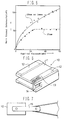
- a composite flying-type magnetic head 10 heretofore known comprises a slider 11 having provided along the longitudinal direction thereof, a slit 13 at the outlet of an air flow flowing along the plane of an air bearing 12.
- An example of a magnetic head chip 14 is illustrated in FIG. 8. It comprises a pair of cores 16 and 17 made from single crystal Mn-Zn ferrite, having incorporated therebetween a metallic magnetic thin film 18 and a glass-filled gap 19. Information is read or recorded by the magnetic change which generate in the gap.
- An Fe-Al-Si based magnetic thin film is deposited on the magnetic head chip as the metallic magnetic thin film. It is also well known that at least a partial use of a single crystal Mn-Zn ferrite in the magnetic circuit improves the playback efficiency of the magnetic head chip.
- the gap of the magnetic head must be faced against the magnetic recording medium in such a manner that a very short distance is maintained therebetween. Accordingly, as shown in FIG. 7(a), the magnetic head 10 is fixed and adhered by the back of the slider to an elastic support 15 which is called gimbals.
- a magnetic head of this type comprises a core made of a non-magnetic substrate material such as of MnO and NiO, and a magnetic head chip held in the slit provided to the slider, said magnetic head chip having a magnetic circuit in the layered film of a metallic magnetic thin film and a non-magnetic film.
- the magnetic head chip as illustrated in FIGS. 10 and 11 comprises cores 31 and 31' made of a non-magnetic substrate such as of ceramics, and to the sides of the non-magnetic substrates are deposited magnetic metallic thin films 32 and 32', or layered films composed of metallic magnetic thin films and non-magnetic films.
- the resulting structure is such comprising a metallic magnetic thin film 32 or 32' or a layered film thereof with a non magnetic film, being sandwiched between non-magnetic substrate materials.
- the metallic magnetic thin films and the layered films are subjected to drawing for tracks to bury them in the slit of the air bearing, and then fixed using a molding glass.
- the magnetic head chip shown in FIG. 10 is track-drawn at the center portion near to the gap, whereas that in FIG. 11 comprises cores 31 and 31' of one of the sides are drawn for tracks.
- the flying-type magnetic heads described hereinbefore are operated with the slider plane being levitated from the surface of a magnetic recording medium at a height of about 0.1 ⁇ m. Accordingly, the back of the magnetic head slider is fixed and adhered to an elastic support to maintain the magnetic head levitated from the surface of a magnetic recording medium. However, sometimes degradation of the write characteristics occurred in accordance with the bonding conditions of the slider to the elastic support to effect a tight adhesion therebetween.
- the present inventors have studied extensively the reason why some magnetic heads show poor write characteristics when they are fixed to elastic supports while the others do not. As a result, it has been found that the conditions upon fixing the magnetic head to an elastic support greatly change the height of the rigged flying plane of the slider of the magnetic head and hence the write characteristics, and that the over-write characteristics become impaired with increasing change of the height of the rigged plane of the flying slider.
- the present inventors measured the height of the rigged flying plane of the slider on the magnetic heads having fixed on elastic supports, for both of those having favorable characteristics and those having poor characteristics. It has been found as a result that the difference in the height of rigged flying plane of the slider was as small as 20 nm or less for those having favorable write characteristics, whereas those poor in the characteristics exhibited a large difference of from 25 to 70 nm. Thus, it has been assumed that the stress to the magnetic head chip becomes larger with increasing difference between the heights of the rigged flying plane of the slider with and without the elastic support being adhered thereto, and hence, that there occurs a reversed magnetostrictive phenomenon in which the magnetized state achieves a different state from that of the initial. Conclusively, it has been thought that the generation of a reversed magnetostriction deteriorates the characteristics of the metallic magnetic thin film to lower the magnetic flux density, and that the over-write characteristics are thereby impaired.
- An object of the present invention is to overcome the problems mentioned in the foregoing, and to provide a flying-type magnetic head based on the aforementioned findings of the present inventors.
- the present invention provides a magnetic head the slider of which is adhered by its back to an elastic support, with the height of the rigged flying plane of the slider being controlled as such that it may be different by 20 nm or less from the height with the slider not being adhered by its back to an elastic support.
- the difference in height of the rigged flying plane of the slider must be controlled to 20 nm or less; otherwise a favorable over-write characteristics would not be stably achieved.
- the accumulation of a large stress to the magnetic head chip is avoided by thus controlling the height of the rigged flying plane of the slider of a magnetic head being fixed to an elastic support to be different by 20 nm or less with respect to the head having no elastic supports being adhered thereto.
- the metallic magnetic thin film can then maintained in a magnetized state similar to that without any elastic supports being fixed thereto, and hence keep the over-write characteristics free from being impaired.
- the magnetic head chip to be established on a slider comprises a core on which the metallic magnetic thin film is to be deposited, and this core may be made either wholly or partially of a single crystal Mn-Zn ferrite.
- the magnetic head chip may be such comprising a non-magnetic core having deposited thereon a metallic magnetic thin film, or such comprising a non-magnetic core having deposited thereon a layered film composed of a metallic magnetic thin film and a non-magnetic film.
- Cores 16 and 17 used here was made wholly from a single crystal Mn-Zn ferrite as shown in FIG. 8.
- a magnetic chip 4 comprising a metallic magnetic thin film being incorporated at the vicinity of the magnetic gap between the cores was fabricated, and was inserted and fixed in a slit 3 having provided on a non-magnetic slider 1 at the discharge side of an air bearing through which a magnetic recording medium is discharged.
- the back of the slider 1 was fixed to an elastic support 5 with an adhesive in such a manner that the flying plane of the slider 1 may face the magnetic recording medium 6.
- the slider 1 becomes levitated from the magnetic recording medium 6 for a minute distance with the rotation of the magnetic recording medium 6, so that the magnetic information which generate at the gap portion of the magnetic head chip may be recorded to the magnetic recording medium 6, or reversely read the information of the magnetic recording medium 6 at the gap portion.
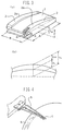
- the flying plane 2 of the slider 1 comprises a rigged portion 2a as shown in FIG. 3(a), and the height H of said rigged portion 2a is controlled as such that the difference thereof between the states of fixing and without fixing an elastic support may fall within 20 nm. More specifically, as shown in Fig. 3(b) ,the height, H1, of the rigged portion without fixing the slider 1 to an elastic support changes to H2 upon fixing the slider to an elastic support, yielding a difference in height of ⁇ H. To control the height H of the rigged portion to 20 nm or less,the back of the slider 1 was adhered to the elastic support 5 with care not to cause deformation on the flying plane of the slider.
- the height H of the rigged flying plane of the slider1 was measured before adhering the back of the slider 1 to theelastic support 5, and the height H of the rigged flying plane of the slider was measured again after adhesion, to select only those heads having a difference in height of 20 nm or lessbefore and after the adhesion.
- the slider 1 has a length A measured in the direction of relative movement between the slider 1 and the recording medium 6 of 2 to 4 mm, preferably 3.0 mm.
- the width B measured transverse to the moving direction is between 2.0 and 2.5 mm, preferably 2.2 mm.
- the maximum height C measured between the surface on which the slider 1 is connected to the support 5, i.e. the lower surface in FIG. 3, and the highest point of the curved surface of the projecting portion 2a, which faces the recording medium 6, is between 0.5 and 0.8 mm, preferably 0.65 mm.
- the two lateral portions 2a have convexly curved surfaces and they project above the central portion of the slider surface, which is also convexly curved.
- the slot 3, into which the magnetic head chip 4 is inserted, is formed in one of the two projecting portions 2a at the trailing edge of the slider 1, as related to the relative movement between the slider 1 and the magnetic recording medium 6, which may be a magnetic disk.
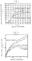
- the magnetic heads having a height difference of the rigged portion 2a of 20 nm or less yield favorably a signal intensity increasing in proportion to the applied current, whereas those having a height difference of the rigged portion 2a of 25 nm became saturated at an applied current of about 20 mA.
- the core which establishes the magnetic circuit of the magnetic head chip 4 was wholly constructed by a single crystal Mn-Zn ferrite.
- a similar result was obtained, however, with a magnetic chip 4 as shown in FIG. 9, having a core comprising single crystal Mn-Zn ferrite only at the vicinity 20 of the gap of the cores 16 and 17, and the rest 21 being made of a polycrystalline Mn-Zn ferrite.
- a magnetic head chip 4 comprising non-magnetic cores 31 and 31' having deposited thereon metallic magnetic thin films 21 and 32', or such comprising cores 31 and 31' having deposited layered films 32 and 32' each composed of a metallic magnetic thin film and a non-magnetic film, as shown in the foregoing FIGS. 10 and 11.
- a plurality of cores may be used to sandwich a metallic magnetic thin film or a layered film. It is also effective to use a core having a non-magnetic protective film coated thereon in the place of a core of the pair of cores shown in FIGS. 10 and 11.
- the present invention provides a flying type magnetic head having an excellent over-write characteristic, because the magnetic head chip is free from stresses and hence free from being unfavorably influenced in magnetization. This is achieved by controlling the height of the rigged flying plane of the slider being adhered to an elastic support to be different from that with no elastic support being adhered by 20 nm or less.
- a flying magnetic head was fabricated in the same manner as in Example 1, except for using a magnetic head chip having deposited thereon a metallic magnetic thin film and having a magnetic circuit which is at least partially constructed by a single crystal Mn-Zn ferrite.
- the magnetic head was inserted and fixed in a slit having provided on a non-magnetic slider at the discharge side of an air bearing through which a magnetic recording medium is discharged.
- the back of the slider was fixed to an elastic support in such a manner that the flying plane of the slider may face the magnetic recording medium.
- the magnetic heads thus obtained were evaluated as follows.
- the height of the rigged flying plane of the slider was measured before adhering the back of the slider to the elastic support, and the height of the rigged flying plane of the slider was measured again after adhesion, to select only those heads having a difference in height of 20 nm or less before and after the adhesion as favorable heads.
- the heads evaluated as favorable ones exhibited excellent over-write characteristics, whereas those evaluated as being unfavorable yielded poor over-write characteristics.
- the slider 1 is prone to deformation when it is fixed to the support arm 5. This deformation produces mechanical stress on the magnetic head chip 4 inserted in the slider 1, which in turn causes the reverse magnetostriction effect referred to above.
- this curvature is determined by measuring the height H between the upper surface of the projecting portrion 2a and a line connecting the points where the convex upper surface meets the vertical end faces of the slider 1.
- the value H is thus a measure of the curvature of the upper surface of the projecting portion 2a which increases when the slider 1 and thus the projecting portions 2a become bent due to deformation.
- the value ⁇ H 20 nm referred to above was found to be a critical value representative of the deformation caused by the fixation of the slider 1 to the support arm 5, up to which critical value the deteriorating effects on the output signal of the magnetic head could be tolerated. Although this critical value was measured with a slider/magnetic head assembly shown in FIG. 3 and the dimension set forth above, it turned out that the value of 20 nm is for all practical cases unrelated to the dimensions of the slider 1 and the magnetic head chip 4.
Landscapes
- Engineering & Computer Science (AREA)
- Manufacturing & Machinery (AREA)
- Adjustment Of The Magnetic Head Position Track Following On Tapes (AREA)
- Magnetic Heads (AREA)
Applications Claiming Priority (2)
| Application Number | Priority Date | Filing Date | Title |
|---|---|---|---|
| JP10475591A JPH04311806A (ja) | 1991-04-10 | 1991-04-10 | 浮上型磁気ヘッド |
| JP104755/91 | 1991-04-10 |
Publications (3)
| Publication Number | Publication Date |
|---|---|
| EP0508471A2 true EP0508471A2 (de) | 1992-10-14 |
| EP0508471A3 EP0508471A3 (en) | 1992-11-25 |
| EP0508471B1 EP0508471B1 (de) | 1997-07-16 |
Family
ID=14389308
Family Applications (1)
| Application Number | Title | Priority Date | Filing Date |
|---|---|---|---|
| EP19920106279 Expired - Lifetime EP0508471B1 (de) | 1991-04-10 | 1992-04-10 | Fliegende Magnetköpfe |
Country Status (3)
| Country | Link |
|---|---|
| EP (1) | EP0508471B1 (de) |
| JP (1) | JPH04311806A (de) |
| DE (1) | DE69220834D1 (de) |
Cited By (2)
| Publication number | Priority date | Publication date | Assignee | Title |
|---|---|---|---|---|
| EP0710957A1 (de) * | 1994-11-03 | 1996-05-08 | International Business Machines Corporation | Luftkissengelegerter Gleitkörper sowie Verfahren zu dessen Herstellung |
| EP0829876A1 (de) * | 1996-09-17 | 1998-03-18 | Silmag | Gleitkörper mit zentraler Hinterstelle mit Hintervorsprung |
Family Cites Families (3)
| Publication number | Priority date | Publication date | Assignee | Title |
|---|---|---|---|---|
| NL7012826A (de) * | 1970-08-29 | 1972-03-02 | ||
| JP2523908B2 (ja) * | 1989-01-06 | 1996-08-14 | 株式会社日立製作所 | 磁気ディスク装置及び薄膜磁気ヘッド並びに薄膜磁気ヘッド作製用ウエハ |
| US5021906A (en) * | 1989-10-31 | 1991-06-04 | International Business Machines Corporation | Programmable air bearing slider including magnetic read/write element |
-
1991
- 1991-04-10 JP JP10475591A patent/JPH04311806A/ja active Pending
-
1992
- 1992-04-10 EP EP19920106279 patent/EP0508471B1/de not_active Expired - Lifetime
- 1992-04-10 DE DE69220834T patent/DE69220834D1/de not_active Expired - Lifetime
Cited By (5)
| Publication number | Priority date | Publication date | Assignee | Title |
|---|---|---|---|---|
| EP0710957A1 (de) * | 1994-11-03 | 1996-05-08 | International Business Machines Corporation | Luftkissengelegerter Gleitkörper sowie Verfahren zu dessen Herstellung |
| US5687042A (en) * | 1994-11-03 | 1997-11-11 | International Business Machines Corporation | Slider having shifted crown peak for reduced fly height sensitivity |
| US5771570A (en) * | 1994-11-03 | 1998-06-30 | International Business Machines Corporation | Method of manufacturing a slider/suspension having an improved crown sensitivity |
| EP0829876A1 (de) * | 1996-09-17 | 1998-03-18 | Silmag | Gleitkörper mit zentraler Hinterstelle mit Hintervorsprung |
| FR2753560A1 (fr) * | 1996-09-17 | 1998-03-20 | Silmag Sa | Patin de vol a plot central arriere en depassement |
Also Published As
| Publication number | Publication date |
|---|---|
| EP0508471B1 (de) | 1997-07-16 |
| DE69220834D1 (de) | 1997-08-21 |
| EP0508471A3 (en) | 1992-11-25 |
| JPH04311806A (ja) | 1992-11-04 |
Similar Documents
| Publication | Publication Date | Title |
|---|---|---|
| US5296993A (en) | Magnetic head with magnetic substrate and an enhanced poletip thereon | |
| US5963401A (en) | Magnetic tape head assembly including modules having a plurality of magneto-resistive head elements | |
| US4796134A (en) | Magnetic head with improved supporter for perpendicular magnetization recording | |
| CA1214871A (en) | Hybrid read-write head for perpendicular recording media | |
| US20090052093A1 (en) | Magnetic head assembly and magnetic tape driving apparatus | |
| WO1997023867A1 (en) | Hard disk drive having ring head sliding on perpendicular media | |
| US5499153A (en) | Floating magnetic head device and its securing method | |
| EP0124293A2 (de) | Dünnschichtwandler für induktive Aufzeichnung und magnetoresistive Wiedergabe | |
| US5978176A (en) | Magnetic head for a magnetic disk having a slider with indented portions for providing heat dissipation | |
| US5223997A (en) | Monolithic floating magnetic head without adverse adhesive effects | |
| US5546251A (en) | Floating magnetic head having a magnetic head core with a balanced winding bonded to a slider side surface | |
| EP0702357A2 (de) | Magnetowiderstandeffektkopf und Magnetaufzeichnungs-/Wiedergabekopf daraus | |
| US4972279A (en) | Microminimonolithic magnetic head slider | |
| US5359479A (en) | Magnetic head slider having a magnetic transducing element affixed to a slider body side surface | |
| US5508863A (en) | Flying-type magnetic head comprising a slider/gimbal connection which suppresses slider height differences | |
| EP0508471B1 (de) | Fliegende Magnetköpfe | |
| US4823216A (en) | Microminimonolithic magnetic head slider | |
| US5251089A (en) | Magnetic head | |
| EP0600280A2 (de) | Schwebender Magnetkopf | |
| US4458280A (en) | Servo writing transducer design and writing method | |
| US5548459A (en) | Floating magnetic head | |
| US4768120A (en) | Complex magnetic head having non-magnetic center core | |
| US5572385A (en) | Flying magnetic head and flying magnetic head assembly | |
| JPS59151334A (ja) | 磁気ヘツド | |
| US6008967A (en) | Hybrid type magnetic head slider having a thin film coil |
Legal Events
| Date | Code | Title | Description |
|---|---|---|---|
| PUAI | Public reference made under article 153(3) epc to a published international application that has entered the european phase |
Free format text: ORIGINAL CODE: 0009012 |
|
| PUAL | Search report despatched |
Free format text: ORIGINAL CODE: 0009013 |
|
| AK | Designated contracting states |
Kind code of ref document: A2 Designated state(s): DE GB IT |
|
| AK | Designated contracting states |
Kind code of ref document: A3 Designated state(s): DE GB IT |
|
| 17P | Request for examination filed |
Effective date: 19930525 |
|
| 17Q | First examination report despatched |
Effective date: 19950726 |
|
| GRAG | Despatch of communication of intention to grant |
Free format text: ORIGINAL CODE: EPIDOS AGRA |
|
| GRAH | Despatch of communication of intention to grant a patent |
Free format text: ORIGINAL CODE: EPIDOS IGRA |
|
| GRAH | Despatch of communication of intention to grant a patent |
Free format text: ORIGINAL CODE: EPIDOS IGRA |
|
| GRAA | (expected) grant |
Free format text: ORIGINAL CODE: 0009210 |
|
| AK | Designated contracting states |
Kind code of ref document: B1 Designated state(s): DE GB IT |
|
| PG25 | Lapsed in a contracting state [announced via postgrant information from national office to epo] |
Ref country code: IT Free format text: LAPSE BECAUSE OF FAILURE TO SUBMIT A TRANSLATION OF THE DESCRIPTION OR TO PAY THE FEE WITHIN THE PRESCRIBED TIME-LIMIT;WARNING: LAPSES OF ITALIAN PATENTS WITH EFFECTIVE DATE BEFORE 2007 MAY HAVE OCCURRED AT ANY TIME BEFORE 2007. THE CORRECT EFFECTIVE DATE MAY BE DIFFERENT FROM THE ONE RECORDED. Effective date: 19970716 |
|
| REF | Corresponds to: |
Ref document number: 69220834 Country of ref document: DE Date of ref document: 19970821 |
|
| PG25 | Lapsed in a contracting state [announced via postgrant information from national office to epo] |
Ref country code: DE Effective date: 19971017 |
|
| PLBE | No opposition filed within time limit |
Free format text: ORIGINAL CODE: 0009261 |
|
| STAA | Information on the status of an ep patent application or granted ep patent |
Free format text: STATUS: NO OPPOSITION FILED WITHIN TIME LIMIT |
|
| 26N | No opposition filed | ||
| PGFP | Annual fee paid to national office [announced via postgrant information from national office to epo] |
Ref country code: GB Payment date: 19990415 Year of fee payment: 8 |
|
| PG25 | Lapsed in a contracting state [announced via postgrant information from national office to epo] |
Ref country code: GB Free format text: LAPSE BECAUSE OF NON-PAYMENT OF DUE FEES Effective date: 20000410 |
|
| GBPC | Gb: european patent ceased through non-payment of renewal fee |
Effective date: 20000410 |