EP0508504A1 - Vorrichtung zum Aufbringen von punktförmigen Beschichtungen - Google Patents
Vorrichtung zum Aufbringen von punktförmigen Beschichtungen Download PDFInfo
- Publication number
- EP0508504A1 EP0508504A1 EP92200578A EP92200578A EP0508504A1 EP 0508504 A1 EP0508504 A1 EP 0508504A1 EP 92200578 A EP92200578 A EP 92200578A EP 92200578 A EP92200578 A EP 92200578A EP 0508504 A1 EP0508504 A1 EP 0508504A1
- Authority
- EP
- European Patent Office
- Prior art keywords
- masking
- shaped
- segments
- wheel
- band
- Prior art date
- Legal status (The legal status is an assumption and is not a legal conclusion. Google has not performed a legal analysis and makes no representation as to the accuracy of the status listed.)
- Granted
Links
- 238000000576 coating method Methods 0.000 title claims abstract description 35
- 230000000873 masking effect Effects 0.000 claims abstract description 142
- 239000002184 metal Substances 0.000 claims abstract description 19
- 229910052751 metal Inorganic materials 0.000 claims abstract description 19
- 239000011248 coating agent Substances 0.000 claims abstract description 11
- 238000005868 electrolysis reaction Methods 0.000 claims abstract description 7
- 238000000034 method Methods 0.000 claims abstract description 5
- 238000000605 extraction Methods 0.000 claims abstract description 3
- 238000007789 sealing Methods 0.000 claims description 21
- 230000008878 coupling Effects 0.000 claims description 12
- 238000010168 coupling process Methods 0.000 claims description 12
- 238000005859 coupling reaction Methods 0.000 claims description 12
- 239000003792 electrolyte Substances 0.000 claims description 9
- 239000000463 material Substances 0.000 claims description 7
- 230000000717 retained effect Effects 0.000 claims description 2
- 239000007779 soft material Substances 0.000 claims description 2
- 238000010276 construction Methods 0.000 description 7
- 238000004519 manufacturing process Methods 0.000 description 4
- 230000000284 resting effect Effects 0.000 description 3
- KDLHZDBZIXYQEI-UHFFFAOYSA-N Palladium Chemical compound [Pd] KDLHZDBZIXYQEI-UHFFFAOYSA-N 0.000 description 2
- 239000010970 precious metal Substances 0.000 description 2
- RYGMFSIKBFXOCR-UHFFFAOYSA-N Copper Chemical compound [Cu] RYGMFSIKBFXOCR-UHFFFAOYSA-N 0.000 description 1
- BQCADISMDOOEFD-UHFFFAOYSA-N Silver Chemical compound [Ag] BQCADISMDOOEFD-UHFFFAOYSA-N 0.000 description 1
- 238000009825 accumulation Methods 0.000 description 1
- 238000007792 addition Methods 0.000 description 1
- 229910052802 copper Inorganic materials 0.000 description 1
- 239000010949 copper Substances 0.000 description 1
- 238000011049 filling Methods 0.000 description 1
- 239000012530 fluid Substances 0.000 description 1
- 238000011010 flushing procedure Methods 0.000 description 1
- 239000011888 foil Substances 0.000 description 1
- PCHJSUWPFVWCPO-UHFFFAOYSA-N gold Chemical compound [Au] PCHJSUWPFVWCPO-UHFFFAOYSA-N 0.000 description 1
- 229910052737 gold Inorganic materials 0.000 description 1
- 239000010931 gold Substances 0.000 description 1
- 229910052763 palladium Inorganic materials 0.000 description 1
- 238000001259 photo etching Methods 0.000 description 1
- 229920002647 polyamide Polymers 0.000 description 1
- 239000012858 resilient material Substances 0.000 description 1
- 229920002379 silicone rubber Polymers 0.000 description 1
- 239000004945 silicone rubber Substances 0.000 description 1
- 229910052709 silver Inorganic materials 0.000 description 1
- 239000004332 silver Substances 0.000 description 1
Images





Classifications
-
- C—CHEMISTRY; METALLURGY
- C25—ELECTROLYTIC OR ELECTROPHORETIC PROCESSES; APPARATUS THEREFOR
- C25D—PROCESSES FOR THE ELECTROLYTIC OR ELECTROPHORETIC PRODUCTION OF COATINGS; ELECTROFORMING; APPARATUS THEREFOR
- C25D5/00—Electroplating characterised by the process; Pretreatment or after-treatment of workpieces
- C25D5/02—Electroplating of selected surface areas
-
- C—CHEMISTRY; METALLURGY
- C25—ELECTROLYTIC OR ELECTROPHORETIC PROCESSES; APPARATUS THEREFOR
- C25D—PROCESSES FOR THE ELECTROLYTIC OR ELECTROPHORETIC PRODUCTION OF COATINGS; ELECTROFORMING; APPARATUS THEREFOR
- C25D5/00—Electroplating characterised by the process; Pretreatment or after-treatment of workpieces
- C25D5/02—Electroplating of selected surface areas
- C25D5/022—Electroplating of selected surface areas using masking means
Definitions
- the invention relates to a device for applying dot-shaped coatings to metal or metallized bands by means of an electrolysis process or by means of currentless metal extraction, said device being provided with a wheel-shaped guide means, along which a metal or metallized band can be passed, and with an endless masking means, which co-operates with said band during operation and which is provided with passages, whose shape is adapted to the desired dot-shaped coating, said masking means being built up of independent masking segments, which are each provided with at least one passage and which are mutually coupled in such a way that they can move with respect to each other in the longitudinal direction of the masking means, whilst each masking segment is provided with a pin, which during operation engages a recess provided in said band, and inner boundary planes of the masking segments, which are located at the sides of the masking segments remote from the outer boundary planes supporting the band during operation, co-operate with a circular supporting surface of the wheel-shaped means.
- Such a device is used for the processing of basic components required in large quantities in the electronics industry, such as supporting elements cut from metal, to be used in the production of transistors, integrated circuits and the like, or parts used in the production of contact systems, switch elements and the like, as well as etched metal patterns on a carrying foil of plastic material.
- a a precious metal coating such as gold, palladium or silver must be applied to these basic components, on the one hand for mounting purposes and on the other hand so as to obtain particularly reliable contact systems.
- Such coatings can usually be limited to certain functional parts of the basic components.
- Said coating with a precious metal takes place by passing the basic components, which are etched or cut from long bands, through the above device with said basic components still being interconnected in the bands in question, whereby the band is uncoiled from a reel arranged on one side of the device, passed through the device and then re-coiled on another reel.
- the device according to the aforesaid European Patent No. 0,060,591 is satisfactory per se, both as regards the care with which the bands are treated and as regards the precision with which the dot-shaped coatings are applied.
- the deviation in the mutual distance between dot-shaped coatings, measured in the longitudinal direction of the band does not exceed ⁇ 0.15 mm when expert use is made of this known device.
- the object of the invention is to achieve an even greater dimensional accuracy, as a result of which it becomes possible to realize a further saving of coating material and/or use more complex patterns for the basic components, whilst the dot-shaped coatings are still applied at the correct locations.
- the masking segments and the masking covers coupled thereto, between which part of the band is, are guided between spaced-apart straight stationary guide means pushing the masking segments and the masking covers towards each other.
- the clamped part of the band is passed along a straight path through an electrolysis station, electrolyte being jetted against the band in said electrolysis station for forming the desired dot-shaped coatings on the band.
- Figure 1 diagrammatically shows a part of a band consisting of a number of basic components, to which dot-shaped coatings can be applied by means of the device according to the invention.
- Figure 2 shows a second embodiment of a part of a band, which can be processed by means of the device according to the invention.
- Figure 3 is a diagrammatic view of a wheel-shaped means of the device according to the invention, with and endless masking means provided around said wheel-shaped means.
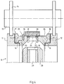
- Figure 4 is a larger-scale cross-sectional view of a part of the wheel-shaped means according to Figure 3 and a supporting roller for said wheel-shaped means.
- Figure 5 is a view, partially in side elevation and partially in section, of a part of the wheel-shaped means with a band making contact with said wheel-shaped means.
- Figure 6 is a view corresponding with Figure 5, whereby the wheel-shaped means is rotated a little further with respect to the position shown in Figure 5.
- Figure 7 is a sectional view of a part of Figure 6, along the line VII-VII in Figure 6.
- Figure 8 diagrammatically shows a further embodiment of the means for coupling two successive masking segments.
- Figure 9 is a sectional view of a further embodiment of the coupling between two masking segments.
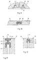
- Figures 10 - 12 show various embodiments of sealing means provided between successive masking segments.
- Figure 13 shows an embodiment, wherein a sealing means provided between two successive masking segments is also used for coupling the masking segments in question.
- Figure 14 is a plan view of Figure 13.
- Figures 15 - 17 show further embodiments of the constructions, wherein sealing means provided between successive masking segments are also used for coupling the masking segments in question.
- Figure 18 is a sectional view of a part of a masking segment, with an insert element provided therein.
- Figure 19 is a plan view of the insert element illustrated in Figure 18.
- Figures 20 and 21 are sectional views of possible embodiments of further insert elements.
- a metal or metallized band which is to be locally provided with dot-shaped coatings, may be a band which is cut out, or whose metal coating applied to a band of plastic material is shaped in such a manner that said band is provided with two edge parts 1 and 2 extending in the longitudinal direction of the band, with finger-shaped parts 3 and 4 located therebetween and being connected thereto, and with a rectangular part 5 surrounded by the free ends of said finger-shaped parts 3, said rectangular part 5 being connected to the edge parts 1 and 2 by means of connecting strips 6 en 7.
- the parts 3 - 7 thereby form a basic product which, together with a large number of corresponding basic products, is shaped in such a manner that said basic products are interconnected by means of the edge parts 1 and 2 so as to form a band, which may furthermore be subjected to one or more processing steps, e.g. be passed through the device to be described hereafter in order for dot-shaped coatings to be applied thereon.
- Such dot-shaped coatings must generally be applied to the part of each basic product indicated by the hatched area A in Figure 1.
- FIG. 2 A further example of a product which may be processed by means of the device according to the invention is shown is Figure 2.
- the basic products formed by contact pins 8 are hereby interconnected by means of a band-shaped means 8A, so as to form an elongated band.
- dot-shaped coatings are to be applied to the basic products 8 in the areas B indicated by chain-dotted lines.
- the device according to the invention shown in Figures 3 - 7 comprises a wheel-shaped means 9, which is freely rotatable about its axis 10 during operation.
- Said wheel-shaped means is thereby built up of two spaced-apart wheel-ring 11 and 12.
- Said wheel-rings 11 and 12 are supported in a frame (not shown) by means of three regularly spaced supporting rollers 13 ( Figure 4) disposed around the axis of rotation 10 of the wheel-shaped means 9 and being journal led in said frame.
- said supporting rollers 13 are not shown in Figure 3.
- the supporting rollers 13 are provided with protruding collars 14, which run in grooves provided circumferentially in the wheel-rings 11 and 12.
- Circular recesses are provided in the wheel-rings 11, at the facing sides of said wheel-rings, said recesses being bounded by boundary faces 15 extending perpendicularly to the axis of rotation 10 and by boundary faces 16 extending concentrically about the axis of rotation 10.
- An endless masking means 17 is passed over the wheel, said masking means being built up of a number of interconnected masking segments 18.
- the successive masking segments 18 are interconnected by means of connecting plates 19, which are pivotally coupled to the masking segments 18 by means of pins 20 extending parallel to the axis of rotation 10 ( Figures 5 - 7).
- the masking segments have inner boundary faces 21, with a radius of curvature equal to the radius of curvature of the boundary faces 16, which form supporting surfaces for the masking segments 18.
- the total length, measured in circumferential direction, of the inner boundary faces 21 of the masking segments 18 forming part of the endless masking means 17 is larger than the length, measured in circumferential direction, of a supporting surface 16. Accordingly, as is shown in particular in Figure 3, the inner boundary faces 21 of a part of the masking segments 18 will be spaced from the relevant supporting surfaces 16 of the two wheel-rings 11 and 12, so that the masking segments present in the lower part of the endless masking means, when seen in Figure 3, can move freely with respect to each other in the longitudinal direction of the band. This free movement of the masking segments 18 with respect to each other is made possible because, as is shown in Figures 5 and 6, one of the holes 22 provided in a connecting plate 19, through which a pin 20 is passed, is a slotted hole.
- each masking segment is provided with a radially extending pin 23, which projects from the masking segment near an outer boundary face 24 and which tapers off towards the outside.
- Each masking means has a passage 25, said passage near the outer boundary face 24 being surrounded by an insert 26 of a soft resilient material, said insert being received in a correspondingly shaped recess provided in the outer boundary face.
- the insert 26 has projections 27 integral therewith, said projections being inserted into bores provided in the masking segment in question so as to anchor the insert 26.
- a housing 28 is arranged between the two wheel-rings 11 and 12, said housing defining a chamber 29, to which a pressurized electrolyte is supplied during operation of the device.
- a plurality of longitudinal slits 30 are provided in a circumferential wall of said housing bounding the chamber 29, said slits extending parallel to the axis of rotation 10 and allowing the pressurized electrolyte to squirt out in the direction of the masking segments 18 resting on the upper part of the wheel-shaped means 9.
- the masking segments 18 resting on the upper part of the wheel-shaped means 9 co-operate with an endless hold-down or masking band 31 which, as shown in Figure 3, is passed over three guide wheels 32 in such a way that said band 32 abuts against the outside of the masking segments 18 resting on the upper part of the wheel-shaped means 9 along a circumferential angle of e.g. 150 - 160°.
- a ring 33 having an L-shaped section and being supported by the wheel-ring 11 is provided at the inner side of the wheel-ring 11, said ring 33 being received in correspondingly shaped recesses formed at the inner circumference of the masking segments.
- This ring contributes towards well-positioning of the masking segments as well as preventing the undesirable tilting of said masking segments.
- a band 34 e.g. built up of the above-described basic components illustrated in the Figures 1 and 2, will be passed between the band 31 and the outer boundary faces 24 of the masking segments 18, in the manner shown in Figures 3 - 6.
- the band 34 is moved in its longitudinal direction by drive means (not shown).
- the masking segment 18 caught by the band can move within certain limits with respect to the preceding masking segment 18, in the longitudinal direction of the masking means formed by the masking segments, and such a movement is not impeded by the masking segments coming behind this caught segment and being freely connected to said segment, the masking segment 18 caught by the band can freely adjust itself with respect to the band, without exerting undesirable forces on the band thereby.
- the hole 25 provided in the masking segment in question will be precisely located opposite the location on the band 34 where a dot-shaped coating is to be applied to the band 34.
- the band 34 thereby acts as a cathode, whilst the housing 28 comprises an anode.
- sealing means must be present between the successive masking segments, as is also described in the aforesaid European Patent No. 0,060,591.
- Such a sealing means 36 may e.g. have an I-shaped crosssection, as is illustrated in Figure 10, whereby the thickened ends are received with some play in correspondingly shaped recesses 37, which are provided in the facing sides of successive masking segments 18, which are indicated only diagrammatically in Figure 10.
- the two holes 22 provided in the connecting plate may have an unround section, such that the two pins 20 are received in the holes 22 in question with some play.
- Figure 9 shows an embodiment wherein pins 20' are fixed to connecting pieces 19', whilst the pins 20' are received in holes 22' provided in the segments 18' in question, at least one of said holes having the shape of a slotted hole or the like.
- FIG 11 shows a further possible embodiment of a sealing means 38 to be provided between two successive masking segments 18.
- Said sealing means comprises a U-shaped part 39, whose legs extending parallel to each other are received in recesses 40 provided in the facing sides of the two segments 18.
- Said U-shaped section is connected, by means of a connecting rib 41 extending between the two segments 18, to a web 42 extending perpendicularly to the legs of the U-shaped part 39, the ends of said web being received in recesses 43, which are provided in the facing sides of the segments 18.
- the arrangement is thereby such that the free ends of the legs of the U-shaped part are directed towards the chamber 28, so that fluid squirted from the chamber 28 and flowing between the facing ends of the segments 18, in the direction according to the arrow A, will attempt to press the two legs of the U-shaped part outwards, as is diagrammatically indicated by means of dotted lines, so that an effective sealing is effected.
- Figure 12 shows a similar built-up construction of a sealing means 44, which is built up of a U-shaped part 45 and a web part 46 adjoining said U-shaped part. Said sealing means 44 is thereby received in recesses 47 in the manner illustrated in Figure 12, said recesses being provided in the facing sides of the masking segments 18. It will be seen that the operation of said sealing means corresponds with the operation of the sealing means 38 shown in Figure 11.
- slotted holes 48 are provided in the facing sides of the diagrammatically indicated masking segments 18, the ends of a plate-shaped sealing means 49 being located in said slotted holes 48 in such a manner that said plate-shaped sealing means 49 bridges the gap between the facing ends of the masking segments 18 so as to close said gap.
- holes 50 extending perpendicularly to the slots 48 are provided in the masking segments 18, said holes receiving pins 51, which pins also extend through holes 52 provided in the sealing means 49, at least a few of said holes 52 having a larger diameter than the pins 51 in question.
- sealing means 49 not only function to seal the gap between two successive masking segments 18 hereby, but also to movably couple the successive masking segments 18, thus replacing the above-described connecting plates 19.
- FIG. 15 and 16 recesses are provided at the inner sides of the diagrammatically depicted masking segments 18, near the facing ends, said recesses receiving and fixing the ends of a connecting plate 53 made of a flexible material. From Figures 15 and 16 it will be apparent that this connecting plate closes the passage between the facing ends of two neighbouring masking segments 18 and at the same time interconnects the masking segments 18 in such a manner that these masking segments can move with respect to each other in the longitudinal direction of the masking means formed by the masking segments.
- Figure 17 diagrammatically illustrates an embodiment wherein a masking segment is at one end provided with a coupling rod 54 having an at least substantial circular section, said rod being connected to the remaining part of the masking segment 18 by means of a connecting neck 55 having a smaller diameter than the rod 54.
- the coupling rod 54 and the connecting neck thereby extend the entire width of the masking segment 18 in question.
- the coupling rod 54 is received in a recess 56 provided in an opposite end of a neigbouring masking segment, said recess having such a diameter that the coupling piece can be accommodated with some play therein.
- the coupling piece 54 with the connecting neck 55 closes the gap between successive masking segments 18, whilst the coupling piece 54, together with the recess 56 receiving said coupling piece, also takes care of the interconnection of successive masking segments 18, in such a manner that said masking segments 18 can move along a certain distance with respect to each other, in the longitudinal direction of the masking means formed by the masking segments.
- Figures 18 and 19 show in more detail a possible embodiment of an insert piece 57 to be provided at the outside of a masking segment 18.
- Such an insert piece 57 is preferably made of a soft material, e.g. silicone rubber having a hardness of 40 - 80, preferably 60° Shore.
- said insert piece is an at least substantially rectangular body 58 having a passage 59 centrally provided therein, which passage will determine the size of the dot-shaped coating eventually to be formed.
- a few projecting pins 60, being integral with the body 58, are provided on said body 58, said pins being received in correspondingly shaped holes provided in the masking segment, so as to firmly anchor the insert piece.
- projecting studs 61 are provided on the upper side of the insert piece 57 coming into contact with the band to be processed, in such a manner that said studs fill the cavities present in the basic components between parts of said basic components by deforming. Said filling is made possible by the very accurate positioning of the band to be processed on the masking segments 18 and the insert pieces provided in said masking segments 18, so that the studs 61 will come to lie precisely opposite said cavities.
- Figure 20 shows an embodiment of an insert piece 62 which, at the side remote from the side that comes into contact with the band to be processed, is provided with a circumferential projecting collar 63, which extends under part of the masking segment only diagrammatically illustrated in Figure 20, so that said insert piece 62 can be provided in the masking segment in a self-gripping manner.
Landscapes
- Chemical & Material Sciences (AREA)
- Organic Chemistry (AREA)
- Chemical Kinetics & Catalysis (AREA)
- Electrochemistry (AREA)
- Materials Engineering (AREA)
- Metallurgy (AREA)
- Engineering & Computer Science (AREA)
- Details Or Accessories Of Spraying Plant Or Apparatus (AREA)
- Electroplating Methods And Accessories (AREA)
- Lead Frames For Integrated Circuits (AREA)
- Coating Apparatus (AREA)
- Materials For Medical Uses (AREA)
- Medicinal Preparation (AREA)
Applications Claiming Priority (2)
| Application Number | Priority Date | Filing Date | Title |
|---|---|---|---|
| NL9100640 | 1991-04-12 | ||
| NL9100640A NL9100640A (nl) | 1991-04-12 | 1991-04-12 | Inrichting voor het aanbrengen van vlekvormige bedekkingen. |
Publications (2)
| Publication Number | Publication Date |
|---|---|
| EP0508504A1 true EP0508504A1 (de) | 1992-10-14 |
| EP0508504B1 EP0508504B1 (de) | 1996-07-03 |
Family
ID=19859126
Family Applications (1)
| Application Number | Title | Priority Date | Filing Date |
|---|---|---|---|
| EP92200578A Expired - Lifetime EP0508504B1 (de) | 1991-04-12 | 1992-02-28 | Vorrichtung zum Aufbringen von punktförmigen Beschichtungen |
Country Status (10)
| Country | Link |
|---|---|
| US (1) | US5282945A (de) |
| EP (1) | EP0508504B1 (de) |
| JP (1) | JP2645201B2 (de) |
| KR (1) | KR100217342B1 (de) |
| AT (1) | ATE140044T1 (de) |
| DE (1) | DE69211886T2 (de) |
| HK (1) | HK9597A (de) |
| MY (1) | MY110449A (de) |
| NL (1) | NL9100640A (de) |
| SG (1) | SG69974A1 (de) |
Cited By (1)
| Publication number | Priority date | Publication date | Assignee | Title |
|---|---|---|---|---|
| NL2035636B1 (nl) * | 2023-08-18 | 2025-03-04 | Meco Equipment Eng B V | Systeem voor het elektrolytisch behandelen van discrete delen van het oppervlak van een bandvormig substraat. |
Families Citing this family (8)
| Publication number | Priority date | Publication date | Assignee | Title |
|---|---|---|---|---|
| JP3425659B2 (ja) | 2001-04-13 | 2003-07-14 | 東洋精箔株式会社 | 部分メッキ装置用同調装置 |
| JP3845343B2 (ja) * | 2002-07-18 | 2006-11-15 | 矢崎総業株式会社 | 鍍金装置 |
| WO2004032766A2 (en) * | 2002-10-04 | 2004-04-22 | Tyco Healthcare Group Lp | Surgical stapling device |
| US7744732B2 (en) * | 2005-04-06 | 2010-06-29 | Leviton Manufacturing Company, Inc. | Continuous plating system and method with mask registration |
| US7655117B2 (en) * | 2005-04-06 | 2010-02-02 | Leviton Manufacturing Co., Inc. | Continuous plating system and method with mask registration |
| WO2008018471A1 (en) | 2006-08-07 | 2008-02-14 | Autonetworks Technologies, Ltd. | Partial plating method, laser plating apparatus, and plated member |
| CN106087016A (zh) * | 2016-08-11 | 2016-11-09 | 太仓市凯福士机械有限公司 | 一种高精度零部件精加工电镀用连接机构 |
| JP7849982B2 (ja) * | 2022-02-21 | 2026-04-22 | Dowaメタルテック株式会社 | 部分めっき用マスク部材及び部分めっき方法 |
Citations (2)
| Publication number | Priority date | Publication date | Assignee | Title |
|---|---|---|---|---|
| GB2117404A (en) * | 1982-03-29 | 1983-10-12 | Galentan Ag | Device for applying blot-shaped coverings by electro-plating |
| US4493757A (en) * | 1981-03-07 | 1985-01-15 | Galentan, A.G. | Device for applying blot-shaped coverings by electro-plating |
Family Cites Families (3)
| Publication number | Priority date | Publication date | Assignee | Title |
|---|---|---|---|---|
| US3894918A (en) * | 1973-12-20 | 1975-07-15 | Western Electric Co | Methods of treating portions of articles |
| DE3028635A1 (de) * | 1980-07-29 | 1982-03-04 | Degussa Ag, 6000 Frankfurt | Vorrichtung zum partiellen galvanischen beschichten |
| EP0055130B1 (de) * | 1980-12-23 | 1984-07-25 | S.G. Owen Limited | Verfahren zum selektiven Galvanisieren |
-
1991
- 1991-04-12 NL NL9100640A patent/NL9100640A/nl not_active Application Discontinuation
-
1992
- 1992-02-28 AT AT92200578T patent/ATE140044T1/de not_active IP Right Cessation
- 1992-02-28 SG SG1996007054A patent/SG69974A1/en unknown
- 1992-02-28 EP EP92200578A patent/EP0508504B1/de not_active Expired - Lifetime
- 1992-02-28 DE DE69211886T patent/DE69211886T2/de not_active Expired - Lifetime
- 1992-03-20 US US07/855,548 patent/US5282945A/en not_active Expired - Lifetime
- 1992-04-02 JP JP4080656A patent/JP2645201B2/ja not_active Expired - Fee Related
- 1992-04-07 KR KR1019920005766A patent/KR100217342B1/ko not_active Expired - Lifetime
- 1992-04-09 MY MYPI92000601A patent/MY110449A/en unknown
-
1997
- 1997-01-23 HK HK9597A patent/HK9597A/en not_active IP Right Cessation
Patent Citations (2)
| Publication number | Priority date | Publication date | Assignee | Title |
|---|---|---|---|---|
| US4493757A (en) * | 1981-03-07 | 1985-01-15 | Galentan, A.G. | Device for applying blot-shaped coverings by electro-plating |
| GB2117404A (en) * | 1982-03-29 | 1983-10-12 | Galentan Ag | Device for applying blot-shaped coverings by electro-plating |
Cited By (1)
| Publication number | Priority date | Publication date | Assignee | Title |
|---|---|---|---|---|
| NL2035636B1 (nl) * | 2023-08-18 | 2025-03-04 | Meco Equipment Eng B V | Systeem voor het elektrolytisch behandelen van discrete delen van het oppervlak van een bandvormig substraat. |
Also Published As
| Publication number | Publication date |
|---|---|
| KR100217342B1 (ko) | 1999-09-01 |
| MY110449A (en) | 1998-05-30 |
| US5282945A (en) | 1994-02-01 |
| HK9597A (en) | 1997-01-31 |
| NL9100640A (nl) | 1992-11-02 |
| SG69974A1 (en) | 2000-01-25 |
| KR920019972A (ko) | 1992-11-20 |
| JP2645201B2 (ja) | 1997-08-25 |
| DE69211886D1 (de) | 1996-08-08 |
| JPH05117893A (ja) | 1993-05-14 |
| DE69211886T2 (de) | 1996-12-12 |
| EP0508504B1 (de) | 1996-07-03 |
| ATE140044T1 (de) | 1996-07-15 |
Similar Documents
| Publication | Publication Date | Title |
|---|---|---|
| EP0508504B1 (de) | Vorrichtung zum Aufbringen von punktförmigen Beschichtungen | |
| EP0328278B1 (de) | Vorrichtung und Verfahren zur Verwendung einer Plattiermaske | |
| US5656855A (en) | Lead frame and method for manufacturing same | |
| US5634391A (en) | Inert plastic coated flexible type diaphragm for application in a sanitary type pump | |
| US6216853B1 (en) | Toothed conveyor belt and coating removal jig for the same | |
| US4132617A (en) | Apparatus for continuous application of strip-, ribbon- or patch-shaped coatings to a metal tape | |
| US4493757A (en) | Device for applying blot-shaped coverings by electro-plating | |
| JPS6318095A (ja) | 連結された金属部品および/または金属被覆製品に金属堆積層を電解メツキする方法および装置 | |
| US4849083A (en) | Rotary conductor roll for continuously electroplating metal strip or other electrically conductive strip | |
| EP4484617A1 (de) | Maskenelement für partielle plattierung und partielles plattierungsverfahren | |
| US4514264A (en) | Method and device for galvanically applying a metal coating on metal objects | |
| US4895632A (en) | Device for providing a stripe shaped coating on an elongated conductive strip by an electrolytic process | |
| EP0416305B1 (de) | Verschleissfester Traktorriemen | |
| US20050058777A1 (en) | Bar coating method | |
| KR100259558B1 (ko) | 반도체 실장 부품 및 그 제조 방법 | |
| WO1998033728A2 (en) | Belt with training ribs to facilitate the selfadaptation to the conveyor system | |
| KR100387224B1 (ko) | 솔더크림 도포용 스퀴즈 블레이드 제조방법 및 그 스퀴즈블레이드 | |
| JPS61124594A (ja) | 帯状メツキ物の部分メツキ装置 | |
| GB2117404A (en) | Device for applying blot-shaped coverings by electro-plating | |
| KR200246140Y1 (ko) | 솔더크림 도포용 스퀴즈 블레이드 | |
| EP0154795A2 (de) | Vorrichtung zum selektiven galvanischen Beschichten eines Bandes | |
| JPH0573821A (ja) | 磁気テープ用ヘツド装置 | |
| NL8101105A (nl) | Werkwijze voor het aanbrengen van al dan niet geheel gesloten lusvormige bedekkingen. | |
| JPH09164653A (ja) | クリームはんだ印刷用スキージ | |
| JPH05315500A (ja) | Icパッケージリードフォーミング固定方法 |
Legal Events
| Date | Code | Title | Description |
|---|---|---|---|
| PUAI | Public reference made under article 153(3) epc to a published international application that has entered the european phase |
Free format text: ORIGINAL CODE: 0009012 |
|
| 17P | Request for examination filed |
Effective date: 19920527 |
|
| AK | Designated contracting states |
Kind code of ref document: A1 Designated state(s): AT BE CH DE DK ES FR GB GR IT LI LU MC NL PT SE |
|
| 17Q | First examination report despatched |
Effective date: 19941121 |
|
| GRAH | Despatch of communication of intention to grant a patent |
Free format text: ORIGINAL CODE: EPIDOS IGRA |
|
| GRAA | (expected) grant |
Free format text: ORIGINAL CODE: 0009210 |
|
| AK | Designated contracting states |
Kind code of ref document: B1 Designated state(s): AT BE CH DE DK ES FR GB GR IT LI LU MC NL PT SE |
|
| PG25 | Lapsed in a contracting state [announced via postgrant information from national office to epo] |
Ref country code: IT Free format text: LAPSE BECAUSE OF FAILURE TO SUBMIT A TRANSLATION OF THE DESCRIPTION OR TO PAY THE FEE WITHIN THE PRE;WARNING: LAPSES OF ITALIAN PATENTS WITH EFFECTIVE DATE BEFORE 2007 MAY HAVE OCCURRED AT ANY TIME BEFORE 2007. THE CORRECT EFFECTIVE DATE MAY BE DIFFERENT FROM THE ONE RECORDED.SCRIBED TIME-LIMIT Effective date: 19960703 Ref country code: ES Free format text: THE PATENT HAS BEEN ANNULLED BY A DECISION OF A NATIONAL AUTHORITY Effective date: 19960703 Ref country code: GR Free format text: LAPSE BECAUSE OF FAILURE TO SUBMIT A TRANSLATION OF THE DESCRIPTION OR TO PAY THE FEE WITHIN THE PRESCRIBED TIME-LIMIT Effective date: 19960703 Ref country code: DK Effective date: 19960703 Ref country code: AT Effective date: 19960703 Ref country code: BE Effective date: 19960703 |
|
| REF | Corresponds to: |
Ref document number: 140044 Country of ref document: AT Date of ref document: 19960715 Kind code of ref document: T |
|
| REG | Reference to a national code |
Ref country code: CH Ref legal event code: NV Representative=s name: RITSCHER & SEIFERT PATENTANWAELTE VSP |
|
| REF | Corresponds to: |
Ref document number: 69211886 Country of ref document: DE Date of ref document: 19960808 |
|
| ET | Fr: translation filed | ||
| PG25 | Lapsed in a contracting state [announced via postgrant information from national office to epo] |
Ref country code: SE Effective date: 19961003 Ref country code: PT Effective date: 19961003 |
|
| PG25 | Lapsed in a contracting state [announced via postgrant information from national office to epo] |
Ref country code: LU Free format text: LAPSE BECAUSE OF NON-PAYMENT OF DUE FEES Effective date: 19970228 |
|
| PLBE | No opposition filed within time limit |
Free format text: ORIGINAL CODE: 0009261 |
|
| STAA | Information on the status of an ep patent application or granted ep patent |
Free format text: STATUS: NO OPPOSITION FILED WITHIN TIME LIMIT |
|
| 26N | No opposition filed | ||
| PG25 | Lapsed in a contracting state [announced via postgrant information from national office to epo] |
Ref country code: MC Effective date: 19970831 |
|
| REG | Reference to a national code |
Ref country code: GB Ref legal event code: IF02 |
|
| NLT1 | Nl: modifications of names registered in virtue of documents presented to the patent office pursuant to art. 16 a, paragraph 1 |
Owner name: BESI PLATING B.V. |
|
| REG | Reference to a national code |
Ref country code: CH Ref legal event code: NV Representative=s name: SERVOPATENT GMBH Ref country code: CH Ref legal event code: PFA Owner name: BESI PLATING B.V. Free format text: MECO EQUIPMENT ENGINEERS B.V.#DE BEVERSPIJKEN 3#NL-5221 EE 'S-HERTOGENBOSCH (NL) -TRANSFER TO- BESI PLATING B.V.##5221 EE 'S-HERTOGENBOSCH (NL) |
|
| REG | Reference to a national code |
Ref country code: FR Ref legal event code: CD |
|
| NLT1 | Nl: modifications of names registered in virtue of documents presented to the patent office pursuant to art. 16 a, paragraph 1 |
Owner name: MECO EQUIPMENT ENGINEERS B.V. |
|
| REG | Reference to a national code |
Ref country code: CH Ref legal event code: PFA Owner name: MECO EQUIPMENT ENGINEERS B.V. Free format text: MECO EQUIPMENT ENGINEERS B.V.#MARCONILAAN 2#5151 DR DRUNEN (NL) -TRANSFER TO- MECO EQUIPMENT ENGINEERS B.V.#MARCONILAAN 2#5151 DR DRUNEN (NL) |
|
| REG | Reference to a national code |
Ref country code: FR Ref legal event code: CD |
|
| PGFP | Annual fee paid to national office [announced via postgrant information from national office to epo] |
Ref country code: CH Payment date: 20100215 Year of fee payment: 19 |
|
| PGFP | Annual fee paid to national office [announced via postgrant information from national office to epo] |
Ref country code: GB Payment date: 20100205 Year of fee payment: 19 |
|
| PGFP | Annual fee paid to national office [announced via postgrant information from national office to epo] |
Ref country code: NL Payment date: 20100228 Year of fee payment: 19 |
|
| PGFP | Annual fee paid to national office [announced via postgrant information from national office to epo] |
Ref country code: FR Payment date: 20110302 Year of fee payment: 20 Ref country code: DE Payment date: 20110218 Year of fee payment: 20 |
|
| REG | Reference to a national code |
Ref country code: NL Ref legal event code: V1 Effective date: 20110901 |
|
| REG | Reference to a national code |
Ref country code: CH Ref legal event code: PL |
|
| GBPC | Gb: european patent ceased through non-payment of renewal fee |
Effective date: 20110228 |
|
| PG25 | Lapsed in a contracting state [announced via postgrant information from national office to epo] |
Ref country code: CH Free format text: LAPSE BECAUSE OF NON-PAYMENT OF DUE FEES Effective date: 20110228 Ref country code: LI Free format text: LAPSE BECAUSE OF NON-PAYMENT OF DUE FEES Effective date: 20110228 |
|
| PG25 | Lapsed in a contracting state [announced via postgrant information from national office to epo] |
Ref country code: NL Free format text: LAPSE BECAUSE OF NON-PAYMENT OF DUE FEES Effective date: 20110901 |
|
| REG | Reference to a national code |
Ref country code: DE Ref legal event code: R071 Ref document number: 69211886 Country of ref document: DE |
|
| PG25 | Lapsed in a contracting state [announced via postgrant information from national office to epo] |
Ref country code: GB Free format text: LAPSE BECAUSE OF NON-PAYMENT OF DUE FEES Effective date: 20110228 |
|
| REG | Reference to a national code |
Ref country code: DE Ref legal event code: R071 Ref document number: 69211886 Country of ref document: DE |
|
| PG25 | Lapsed in a contracting state [announced via postgrant information from national office to epo] |
Ref country code: DE Free format text: LAPSE BECAUSE OF EXPIRATION OF PROTECTION Effective date: 20120229 |