EP0508514A1 - Procédé et dispositif pour isoler un bout de fil d'un fil de chaîne cassé de la chaîne dans un métier à tisser - Google Patents
Procédé et dispositif pour isoler un bout de fil d'un fil de chaîne cassé de la chaîne dans un métier à tisser Download PDFInfo
- Publication number
- EP0508514A1 EP0508514A1 EP92200773A EP92200773A EP0508514A1 EP 0508514 A1 EP0508514 A1 EP 0508514A1 EP 92200773 A EP92200773 A EP 92200773A EP 92200773 A EP92200773 A EP 92200773A EP 0508514 A1 EP0508514 A1 EP 0508514A1
- Authority
- EP
- European Patent Office
- Prior art keywords
- warp
- broken
- yarn end
- stop motion
- carrying element
- Prior art date
- Legal status (The legal status is an assumption and is not a legal conclusion. Google has not performed a legal analysis and makes no representation as to the accuracy of the status listed.)
- Withdrawn
Links
- 238000000034 method Methods 0.000 title claims abstract description 24
- 238000009941 weaving Methods 0.000 title claims abstract description 14
- 238000001514 detection method Methods 0.000 claims description 7
- 238000005452 bending Methods 0.000 claims description 3
- 238000007664 blowing Methods 0.000 description 26
- 235000014676 Phragmites communis Nutrition 0.000 description 1
- 239000004744 fabric Substances 0.000 description 1
Images



Classifications
-
- D—TEXTILES; PAPER
- D03—WEAVING
- D03J—AUXILIARY WEAVING APPARATUS; WEAVERS' TOOLS; SHUTTLES
- D03J1/00—Auxiliary apparatus combined with or associated with looms
- D03J1/004—Detection and repair of broken warp yarns
Definitions
- the present invention concerns a method and device for isolating a yarn end of a broken warp thread from the warp in a weaving machine, in particular in a weaving machine which uses a warp stop motion of the type whereby thread breaks are detected by means of drop wires which have been hung up on the warp threads.
- the present invention aims a method and device for isolating a yarn end of a broken warp thread, whereby the risk of a crossing arising during the removal from the warp of said yarn end is entirely excluded.
- the invention concerns a method for isolating a yarn end of a broken warp thread from the warp in a weaving machine which is provided with a warp stop motion of the type whereby drop wires have been hung up on the warp threads, characterized in that it mainly consists in that a yarn end of the broken warp thread is put in its correct position in at least one place and in that said yarn end is subsequently removed from the warp at the height of said place.
- the method successively consists in: the application of clamping means at a first side outside the warp stop motion at the height of a broken warp thread; the bringing of a part of a yarn end of the broken warp thread out of the surface of the warp at the height of the warp stop motion; the picking up of said part by means of a carrying element; the moving of said carrying element, such that the above-mentioned yarn end is put into a correct position at a second side outside the warp stop motion, opposite to the above-mentioned first side; and the removal of the above-mentioned yarn end of the broken warp thread from the warp at said second side outside the warp stop motion.
- the above-mentioned part of the warp thread is preferably brought out of the warp by exerting a blowing force on the broken warp thread.
- the taking up is preferably done by means of a hook-shaped carrying element which acts onto the above-mentioned part.
- the present invention also concerns a device to realize said method.
- the yarn ends 8 and 9 of the broken warp thread 4A usually do not remain parallel to the other warp threads 4, but spring back elastically, as a result of which they may take for example a shape as represented in figure 1.
- the present invention provides for a method for isolating a yarn end of the broken warp thread 4A, whereby this yarn end is first put in the correct position before being removed from the warp, such that a crossing of the broken warp thread 4A with the other warp threads 4 is excluded.
- This method for isolating and removing the yarn end 9 which is situated at the height of the warp stop motion 1 from the warp is represented step by step in figures 2 to 4.
- Step one consists in applying clamping means 10, such as a thread clip, to a first side of the warp stop motion 1, outside this warp stop motion 1, at the height of the broken warp thread 4A. As shown in figure 2, this thread clip is closed such that the yarn end 9 is clamped.
- clamping means 10 such as a thread clip
- Step two consists in bringing a part 11 of the broken warp thread 4A out of the surface of the warp 12 at the height of the warp stop motion 1. As shown in figure 2, this part 11 is preferably blown out of the warp 12 by means of an air flow 13. In order to make the broken warp thread 4A sit sufficiently loose so as to form a loop-shaped part 11, the dropped drop wire 2A is preferably first represented again at a normal height, as indicated by means of arrow A in figure 2.
- a carrying element 14 whereby the latter consists for example of a hook-shaped element which acts onto the part 11 according to a movement B.
- the carrying element 14 is moved further, such that, as represented in figure 3, one of the aforesaid yarn ends, in this case the yarn end 9, is tightened.
- the carrying element 14 preferably moves according to a direction transversely to the warp threads 4. As represented in figures 1 to 4 the carrying element 14 is moved to this end between the rows of drop wires 3A and 3B.
- the above-mentioned part 11 is formed between the rows of drop wires 3A and 3B.
- This offers the advantage that the part 15 of the above-mentioned yarn end 9 of the broken warp thread 4A which is situated outside the warp stop motion 1 is stretched at the right place among the other warp threads 4.
- This is also advantageous in that the yarn end 9 can be removed from the warp threads 4 at the right place, after which a repair procedure can be executed in the known way.
- use can be made to this end of an auxiliary element 16 with a blowing nozzle 17 or such like.
- the auxiliary element 16 is hereby placed at a second side opposite to the above-mentioned first side of the warp stop motion 1 and outside the warp stop motion 1, preferably in the immediate vicinity of this warp stop motion 1, such that the yarn end 9 which is stretched there can be removed from the warp 12.
- the blowing nozzle 17 is activated first and subsequently the clamping means 10 are moved away from the warp 12, such that a situation as represented in figure 4 is created.
- This method is also advantageous in that it is not required to know the exact place of the broken warp thread 4A with reference to the width of the weaving machine in order to be able to isolate it.
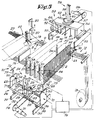
- FIG. 5 For the sake of completeness, a number of weaving machine components have been represented in figure 5, such as the warp beam 18, the sley 19 with the reed and the harnesses 20. Also the supporting rods 21 of the warp stop motion 1, the shed 22 and the produced cloth 23 are represented in this figure 5.
- the device according to the invention mainly consists of means 24 to bring the part 11 of the broken warp thread 4A at the height of the warp stop motion 1 out of the surface of the warp 12, and at least one movable carrying element 14 which can work in conjunction with said part 11.
- the above-mentioned means 24 consist of at least one blowing nozzle 25 which can be presented between the rows of drop wires 3A-3E at the height of the broken warp thread 4A to the warp 12.
- said blowing nozzle 25 can be brought under the warp 12 by means of a transport device 26.
- the means 24 also include a mechanism 27 to raise the dropped drop wires 2A and possibly a mechanism 28 to turn said drop wires 2A around their longitudinal axis.
- the transport device 26 consists of a trolley or sledge 29 which can be moved to and fro under the warp stop motion 1 over guide pieces 30.
- the drive is carried out by means of an electrical motor 31 and a cable 32.
- the above-mentioned blowing nozzle 25 can be moved, such that it can be brought between the different rows of drop wires 3A-3E as desired. To this end it has been fixed to an element 33, for example in the shape of a sledge, which can be moved transversely to the moving direction of the trolley 29. A second blowing nozzle 34 may have been fixed to this element 33, the purpose of which will become clear further in this description.
- the element 33 can be set in the desired place by means of a drive cylinder 35 which has been mounted between the element 33 and the frame 36 of the trolley 29.
- a mechanism 28 of the type as described in US patent 4.815.498 As shown in figures 5, 6 and 7, such mechanism 28 mainly consists of gripping means 37 which can be moved up and down by means of a drive cylinder 38.
- the gripping means 37 consist of a first clamping element 39 which has been fixed to a support 40, and a second clamping element 41 which has been attached to this support 40 in a rotatable manner and which can be moved by means of a drive cylinder 42.
- the support 40 can be moved up and down by means of the drive element 38, for example along the guide pieces 43.
- blowing nozzles 25 and 34 can preferably also be moved vertically, together with the support 40, such that they can take two positions, as shown in figures 6 and 8 respectively, whereby the ends of these blowing nozzles 25 and 34 are in the highest position at a short distance under the warp.
- blowing nozzles 25 and 34 are for example telescopic. According to figure 7, these telescopic blowing nozzles 25 and 34 are connected to the support 40 by means of a pen 44 which acts onto a circle-shaped guide piece 45 which is fastened to the blowing nozzles 25 and 34.
- the above-mentioned mechanism 28 to rotate a dropped drop wire 2A consists of a rotating table 46 which has been mounted on the element 33 and which can be turned to and fro by means of a drive. As shown in figure 6, this drive may consist of a gear rack 48 which can be moved by means of drive cylinder 47 and which works in conjunction with a pinion 49 which has been fixed to the rotating table 46.
- the above-mentioned gripping means 37 have been mounted on the rotating table 46.
- the device also has means, provided with detection elements 50, to move the trolley 29 exactly to the dropped drop wire 2A.
- means make use of a light beam 51 and are already known as such from US patent 4.791.967, US patent 4.815.498 and US patent 4.911.207 of the applicant.
- the weaving machine has more than two rows of drop wires 3A-3E
- These carrying elements 14 each have the shape of a hook and are attached to a common support 52.
- the carrying elements 14 can be moved according to a direction transversely to the warp threads 4, such by means of a transport device 53, which for example consists of a trolley 54 which can be moved above the warp stop motion 1 over guide pieces 55. As shown in figure 5, this trolley 54 can be moved by means of an electric motor 56 and a cable 57.
- the transport device 53 has a mechanism 58 which makes it possible for the carrying elements 14 to be set at different distances above the warp 12, as well as a mechanism 59 which makes it possible to rotate the hook-shaped carrying elements 14 over 180 degrees.
- the mechanism 58 is composed of a drive cylinder 60 with which the support 52 can be moved up and down.
- the mechanism 59 is almost analogous to the mechanism 28 and has a rotating table 61 or such like, a drive cylinder 62, a gear rack 63 and a pinion 64. Through the rotation of the rotating table 61, the support 52 can be rotated over 180 degrees.
- the carrying elements 14 have two hook-shaped parts, such that they can operate in two directions without the rotation of the carrying elements 14 being required. As represented in figure 5 by a dashed line, the carrying elements 14 also have parts 14A here. The mechanism 59 is redundant in this case.
- the device has several auxiliary elements 16 to pick up a yarn end 8 or 9 which has been removed from the warp 12.
- auxiliary elements 16 mainly consist of blowing nozzles 17 which can be presented to the warp 12 at both sides of the pack of drop wires 2, and possibly as many blowing nozzles 65 to move the yarn end 8 or 9 concerned to the blowing nozzle 17 concerned.
- blowing nozzles 17 and the blowing nozzles 65 are situated on the trolleys 54 and 29 respectively.
- the blowing nozzles 17 and the blowing nozzles 65 are telescopic, one and other such that only when they are switched on they are presented to the warp 12 at the top side and bottom side respectively.
- the blowing nozzles 17 can hereby be moved by means of drive cylinders 66.
- the blowing nozzles 65 have a part 67 which has been fixed in a cylinder 68 in an axially telescopic manner, whereby the part 67 has an entry opening 69, such that when compressed air is supplied to the cylinder 68, the part 67 will telescope out while the air escapes via the blowing nozzle 65.
- the transport device 53 can be positioned above the transport device 26 by means of appropriate control means and/or detection means, which make use of cooperating detection means 70 and 71.
- the clamping means 10 are made up in the shown embodiment of clamping means 72 which have been applied to the transport device 26. These clamping means 72 can be moved up and down by means of drive cylinders 73, such that these clamping means 72 can work in conjunction with the bottom sides 74 of the guide pieces 55, which hereby also serve as a clamping element.
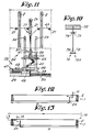
- Figure 10 shows a carrying element 14, 14A respectively, which is provided with detection means 75 which make it possible to detect the bending of the carrying elements 14-14A in relation to their support 52. If the yarn end 8 or 9 which is carried along becomes stretched, the clamping element 14-14A bends, as a result of which the detection means 75 emit a signal.
- control unit 76 The different parts of the transport devices 26 and 53 are controlled by means of or connected to a control unit 76 as described hereafter.
- This control unit 76 is also connected to the electrodes 6A and 6B.
- the element 33 is moved in front of the row of drop wires 3C in which the dropped drop wire 2A is situated, in particular as shown in figure 6.
- the drop wire 2A is picked up by means of the gripping means 37.
- the support 40 is raised with the gripping means 37 and the picked up drop wire 2A, as a result of which a situation as represented in figure 8 is created.
- one of the drive cylinders 73 of the clamping means 72 is activated, as a result of which the warp threads 4 near the broken warp thread 4A are clamped.
- the blowing nozzle 25 is activated.
- the amount of thread of the above-mentioned loop 77 is now blown out of the surface of the warp 12, as a result of which a part 11 is formed which can be taken up by means of one of the carrying elements 14.
- the support 52 is put in its lowest position and the trolley 54 is moved transversely over the warp 12. This results in the cycle as represented in figures 2 and 3 being completed.
- the movement of the carrying element 14 is stopped hereby as soon as the detection means 75 emit a signal which indicates a certain bending of it.
- the above-mentioned part 11 is preferably formed in the immediate vicinity of the dropped drop wire 2A.
- the above-mentioned part 15 of the broken warp thread 4A is placed in the correct position among the other warp threads 4, the above-mentioned part 11 is always formed between two rows of drop wires 3A-3E.
- a drop wire from the row 3E drops down, use will be made of the blowing nozzle 34 instead of 25, as indicated in figure 8 by the dashed line.
- the gripping means 37 after the picking up of the drop wire 2A, can be rotated by means of the above-mentioned mechanism 28. As represented in figure 11, this results in the drop wire 2A being turned and/or twisted as a result of which the yarn end 9 can be pulled more easily out of the drop wire 2A.
- the moving direction of the carrying element 14 is preferably chosen such that the course D, after the broken warp thread 4A has been picked up at the part 11, always has a maximum size. This means that the carrying element 14, after the picking up of the warp thread 4A, is moved from right to left when the dropped drop wire 2A is situated in the right half of the pack of drop wires 2, as schematically represented in figure 12.
- the carrying element 14 When the dropped drop wire 2A is situated in the left half and when the carrying element 14 is situated at the right side of the warp stop motion 1, for example as shown in figure 13, the carrying element 14 is first moved to the left in its highest position and then moved back to the right in its lowest position. It is clear that the hook-shaped part of the carrying element 14 is brought in the appropriate direction in order to pick up the warp thread 4A and carry it along.
- each carrying element 14-14A can also be provided with a clamping element 78, such that the yarn end 8 or 9 is picked up with a certain clamping force and slides along the carrying element 14 or 14A with a certain friction. As a result, a certain tensile force is exerted on the above-mentioned part 15, as a result of which said part 15 is stretched with certainty.
- an auxiliary element 16 and a thread clip 10 is to be provided on both sides of the warp stop motion 1 in order to isolate the yarn end concerned from the warp 12.
- a yarn detector 79 and 80 respectively are to be provided in the blowing nozzles 17 of the auxiliary elements 16 in order to check whether the yarn end 8 or 9 has been removed.
- the transport device 53 may also consist of a mechanism which can be moved over several weaving machines, for example of the type as described in US patent 4.895.186.
Landscapes
- Engineering & Computer Science (AREA)
- Textile Engineering (AREA)
- Looms (AREA)
- Auxiliary Weaving Apparatuses, Weavers' Tools, And Shuttles (AREA)
Applications Claiming Priority (2)
| Application Number | Priority Date | Filing Date | Title |
|---|---|---|---|
| BE9100323 | 1991-04-09 | ||
| BE9100323A BE1004740A3 (nl) | 1991-04-09 | 1991-04-09 | Werkwijze en inrichting voor het afzonderen van een draadeinde van een gebroken kettingdraad uit de ketting bij een weefmachine. |
Publications (1)
| Publication Number | Publication Date |
|---|---|
| EP0508514A1 true EP0508514A1 (fr) | 1992-10-14 |
Family
ID=3885433
Family Applications (1)
| Application Number | Title | Priority Date | Filing Date |
|---|---|---|---|
| EP92200773A Withdrawn EP0508514A1 (fr) | 1991-04-09 | 1992-03-18 | Procédé et dispositif pour isoler un bout de fil d'un fil de chaîne cassé de la chaîne dans un métier à tisser |
Country Status (3)
| Country | Link |
|---|---|
| US (1) | US5249606A (fr) |
| EP (1) | EP0508514A1 (fr) |
| BE (1) | BE1004740A3 (fr) |
Citations (9)
| Publication number | Priority date | Publication date | Assignee | Title |
|---|---|---|---|---|
| EP0284591A1 (fr) * | 1987-03-13 | 1988-09-28 | Picanol N.V. | Procédé pour séparer un fil de chaîne cassé de la nappe des fils de chaîne au casse-chaîne dans un métier à tisser et dispositif pour la mise en oeuvre de ce procédé |
| US4791967A (en) * | 1986-02-14 | 1988-12-20 | Picanol N.V. | Device for determining the location of a warp break thread in weaving looms using drop wires |
| EP0307025A1 (fr) * | 1987-09-02 | 1989-03-15 | Picanol N.V. | Procédé pour le contrôle des cassures de fil de chaîne aux métiers à tisser et dispositif pour l'utilisation de ce procédé |
| US4815498A (en) * | 1986-07-08 | 1989-03-28 | Picanol N.V. | Process and apparatus for manipulating fallen drop wires of weaving loom warp stop motions and facilitating repair of broken warp threads |
| US4817675A (en) * | 1986-08-28 | 1989-04-04 | Picanol N.V. | Method for repairing a broken warp thread on weaving machines, and the rethreading mechanisms used |
| EP0310154A1 (fr) * | 1987-09-02 | 1989-04-05 | Picanol N.V. | Dispositif de mesure et de détection pour la détermination de la position d'une cassure d'un fil de chaîne aux métiers à tisser |
| US4895186A (en) * | 1987-06-29 | 1990-01-23 | Picanol N.V. | Universal transport mechanism for auxiliary devices in weaving mills |
| EP0381143A2 (fr) * | 1989-02-02 | 1990-08-08 | Tsudakoma Corporation | Procédé et dispositif pour réparer un fil de chaîne automatiquement |
| EP0449279A1 (fr) * | 1990-03-28 | 1991-10-02 | TSUDAKOMA Corp. | Méthode pour localiser l'espacement entre des dents correspondant à un fil de chaîne cassé, et dispositif de localisation et de rentrage |
Family Cites Families (3)
| Publication number | Priority date | Publication date | Assignee | Title |
|---|---|---|---|---|
| GB2223511B (en) * | 1988-10-10 | 1992-08-26 | Texipat S A | Apparatus and method for automatically repairing broken warp threads in weaving machines or looms |
| JP2532665B2 (ja) * | 1989-06-14 | 1996-09-11 | シーケーディ株式会社 | 筬通し機における筬羽位置検出装置 |
| JPH06104946B2 (ja) * | 1989-10-11 | 1994-12-21 | シーケーディ株式会社 | ドロッパの分離装置 |
-
1991
- 1991-04-09 BE BE9100323A patent/BE1004740A3/nl not_active IP Right Cessation
-
1992
- 1992-03-18 EP EP92200773A patent/EP0508514A1/fr not_active Withdrawn
- 1992-04-06 US US07/863,775 patent/US5249606A/en not_active Expired - Fee Related
Patent Citations (9)
| Publication number | Priority date | Publication date | Assignee | Title |
|---|---|---|---|---|
| US4791967A (en) * | 1986-02-14 | 1988-12-20 | Picanol N.V. | Device for determining the location of a warp break thread in weaving looms using drop wires |
| US4815498A (en) * | 1986-07-08 | 1989-03-28 | Picanol N.V. | Process and apparatus for manipulating fallen drop wires of weaving loom warp stop motions and facilitating repair of broken warp threads |
| US4817675A (en) * | 1986-08-28 | 1989-04-04 | Picanol N.V. | Method for repairing a broken warp thread on weaving machines, and the rethreading mechanisms used |
| EP0284591A1 (fr) * | 1987-03-13 | 1988-09-28 | Picanol N.V. | Procédé pour séparer un fil de chaîne cassé de la nappe des fils de chaîne au casse-chaîne dans un métier à tisser et dispositif pour la mise en oeuvre de ce procédé |
| US4895186A (en) * | 1987-06-29 | 1990-01-23 | Picanol N.V. | Universal transport mechanism for auxiliary devices in weaving mills |
| EP0307025A1 (fr) * | 1987-09-02 | 1989-03-15 | Picanol N.V. | Procédé pour le contrôle des cassures de fil de chaîne aux métiers à tisser et dispositif pour l'utilisation de ce procédé |
| EP0310154A1 (fr) * | 1987-09-02 | 1989-04-05 | Picanol N.V. | Dispositif de mesure et de détection pour la détermination de la position d'une cassure d'un fil de chaîne aux métiers à tisser |
| EP0381143A2 (fr) * | 1989-02-02 | 1990-08-08 | Tsudakoma Corporation | Procédé et dispositif pour réparer un fil de chaîne automatiquement |
| EP0449279A1 (fr) * | 1990-03-28 | 1991-10-02 | TSUDAKOMA Corp. | Méthode pour localiser l'espacement entre des dents correspondant à un fil de chaîne cassé, et dispositif de localisation et de rentrage |
Also Published As
| Publication number | Publication date |
|---|---|
| BE1004740A3 (nl) | 1993-01-19 |
| US5249606A (en) | 1993-10-05 |
Similar Documents
| Publication | Publication Date | Title |
|---|---|---|
| AU646496B2 (en) | Device for handling healds or drop wires in a warp thread insertion machine | |
| US4573856A (en) | Apparatus for logistical operations with textile machinery | |
| US4815498A (en) | Process and apparatus for manipulating fallen drop wires of weaving loom warp stop motions and facilitating repair of broken warp threads | |
| EP0236601B1 (fr) | Machine automatique pour la jonction de deux extrémités de bande | |
| US5492153A (en) | Clamp type arrangement for presenting weft threads to a gripper | |
| EP0259915A1 (fr) | Procédé pour réparer un fil de chaîne cassé dans les métiers à tisser, et mécanisme de réenfilage utilisé | |
| US4909283A (en) | Tucking-in device for weaving machines | |
| CA1333986C (fr) | Appareil de remplacement automatique de canette pour metier a tisser a navette | |
| EP0284591B1 (fr) | Procédé pour séparer un fil de chaîne cassé de la nappe des fils de chaîne au casse-chaîne dans un métier à tisser et dispositif pour la mise en oeuvre de ce procédé | |
| US5249606A (en) | Isolating a yarn end of a broken warp thread from the warp in a weaving machine | |
| EP0328680B1 (fr) | Appareil automatique a enfiler les fils de chaine | |
| JPH0735625B2 (ja) | たて糸の切れ端分離方法およびその装置 | |
| EP0307025A1 (fr) | Procédé pour le contrôle des cassures de fil de chaîne aux métiers à tisser et dispositif pour l'utilisation de ce procédé | |
| JP2665918B2 (ja) | たて糸自動補修方法およびその装置 | |
| WO1997017484A1 (fr) | Procede de rentrage de peignes pour metiers a tisser et dispositif correspondant | |
| US5016677A (en) | Automatic cop changing device for a weaving machine | |
| EP0449277B1 (fr) | Procédé pour restaurer un fil de chaîne cassé après sa réparation | |
| US5141030A (en) | Warp mending device for feeding a mending yarn to drop wires and a heddle | |
| JP2722233B2 (ja) | たて糸自動補修方法 | |
| JP2678912B2 (ja) | 自動綾分装置及び綾分方法 | |
| EP0311170A1 (fr) | Procédé de réparation de fils de chaîne cassés de machines à tisser | |
| EP0311169A1 (fr) | Procédé pour positionner des méchanismes auxiliaires pour métiers à tisser et dispositif utilisant ce procédé | |
| JPH09119045A (ja) | 機掛け準備方法 | |
| HU212012B (en) | Automatic fibre drawing-in shuttle to cane weaver machine | |
| GB2484313A (en) | Faulty Yarn End Replacement Apparatus |
Legal Events
| Date | Code | Title | Description |
|---|---|---|---|
| PUAI | Public reference made under article 153(3) epc to a published international application that has entered the european phase |
Free format text: ORIGINAL CODE: 0009012 |
|
| AK | Designated contracting states |
Kind code of ref document: A1 Designated state(s): CH DE FR GB IT LI |
|
| 17P | Request for examination filed |
Effective date: 19921117 |
|
| 17Q | First examination report despatched |
Effective date: 19940726 |
|
| STAA | Information on the status of an ep patent application or granted ep patent |
Free format text: STATUS: THE APPLICATION IS DEEMED TO BE WITHDRAWN |
|
| 18D | Application deemed to be withdrawn |
Effective date: 19960302 |