EP0508528A1 - Entleerende Flüssigkeitskupplung mit kontinuierlicher Steuerung der Flüssigkeitsmenge zur Speisung des Arbeitsraums, mit oder ohne interner Vorrichtung zum Direktverbinden der treibenden und getriebenen Welle - Google Patents
Entleerende Flüssigkeitskupplung mit kontinuierlicher Steuerung der Flüssigkeitsmenge zur Speisung des Arbeitsraums, mit oder ohne interner Vorrichtung zum Direktverbinden der treibenden und getriebenen Welle Download PDFInfo
- Publication number
- EP0508528A1 EP0508528A1 EP92200935A EP92200935A EP0508528A1 EP 0508528 A1 EP0508528 A1 EP 0508528A1 EP 92200935 A EP92200935 A EP 92200935A EP 92200935 A EP92200935 A EP 92200935A EP 0508528 A1 EP0508528 A1 EP 0508528A1
- Authority
- EP
- European Patent Office
- Prior art keywords
- coupling
- fluid
- pump
- fluid coupling
- operating circuit
- Prior art date
- Legal status (The legal status is an assumption and is not a legal conclusion. Google has not performed a legal analysis and makes no representation as to the accuracy of the status listed.)
- Granted
Links
- 230000008878 coupling Effects 0.000 title claims abstract description 55
- 238000010168 coupling process Methods 0.000 title claims abstract description 55
- 238000005859 coupling reaction Methods 0.000 title claims abstract description 55
- 239000012530 fluid Substances 0.000 title claims abstract description 48
- 230000002093 peripheral effect Effects 0.000 description 4
- 230000001276 controlling effect Effects 0.000 description 3
- 238000001816 cooling Methods 0.000 description 2
- 238000010586 diagram Methods 0.000 description 2
- 230000002159 abnormal effect Effects 0.000 description 1
- 238000010521 absorption reaction Methods 0.000 description 1
- 238000002485 combustion reaction Methods 0.000 description 1
- 238000010276 construction Methods 0.000 description 1
- 230000000694 effects Effects 0.000 description 1
- 238000001914 filtration Methods 0.000 description 1
- 238000010438 heat treatment Methods 0.000 description 1
- 238000004519 manufacturing process Methods 0.000 description 1
- 238000000034 method Methods 0.000 description 1
- 230000000750 progressive effect Effects 0.000 description 1
- 230000001105 regulatory effect Effects 0.000 description 1
- 239000011435 rock Substances 0.000 description 1
- 239000003923 scrap metal Substances 0.000 description 1
- 239000002023 wood Substances 0.000 description 1
Images
Classifications
-
- F—MECHANICAL ENGINEERING; LIGHTING; HEATING; WEAPONS; BLASTING
- F16—ENGINEERING ELEMENTS AND UNITS; GENERAL MEASURES FOR PRODUCING AND MAINTAINING EFFECTIVE FUNCTIONING OF MACHINES OR INSTALLATIONS; THERMAL INSULATION IN GENERAL
- F16D—COUPLINGS FOR TRANSMITTING ROTATION; CLUTCHES; BRAKES
- F16D33/00—Rotary fluid couplings or clutches of the hydrokinetic type
- F16D33/06—Rotary fluid couplings or clutches of the hydrokinetic type controlled by changing the amount of liquid in the working circuit
-
- F—MECHANICAL ENGINEERING; LIGHTING; HEATING; WEAPONS; BLASTING
- F16—ENGINEERING ELEMENTS AND UNITS; GENERAL MEASURES FOR PRODUCING AND MAINTAINING EFFECTIVE FUNCTIONING OF MACHINES OR INSTALLATIONS; THERMAL INSULATION IN GENERAL
- F16H—GEARING
- F16H45/00—Combinations of fluid gearings for conveying rotary motion with couplings or clutches
- F16H45/02—Combinations of fluid gearings for conveying rotary motion with couplings or clutches with mechanical clutches for bridging a fluid gearing of the hydrokinetic type
-
- F—MECHANICAL ENGINEERING; LIGHTING; HEATING; WEAPONS; BLASTING
- F16—ENGINEERING ELEMENTS AND UNITS; GENERAL MEASURES FOR PRODUCING AND MAINTAINING EFFECTIVE FUNCTIONING OF MACHINES OR INSTALLATIONS; THERMAL INSULATION IN GENERAL
- F16H—GEARING
- F16H45/00—Combinations of fluid gearings for conveying rotary motion with couplings or clutches
- F16H45/02—Combinations of fluid gearings for conveying rotary motion with couplings or clutches with mechanical clutches for bridging a fluid gearing of the hydrokinetic type
- F16H2045/0273—Combinations of fluid gearings for conveying rotary motion with couplings or clutches with mechanical clutches for bridging a fluid gearing of the hydrokinetic type characterised by the type of the friction surface of the lock-up clutch
- F16H2045/0284—Multiple disk type lock-up clutch
Definitions
- This invention relates to a fluid coupling of emptying type with continuous flow control of the fluid fed into the operating circuit, with or without an internal system for direct connection between the drive shaft and driven shaft.
- Fluid couplings consist in known manner of two mutually facing semi-toroidal impellers provided with inner blading and known as the pump and turbine respectively.
- the pump fixed to the shaft of the motor, acts indirectly, by way of a fluid, on the turbine which is connected to the shaft of the user apparatus, the fluid, usually an oil, being fed into the toroidal cavity defined by said impellers, between which torque is transmitted under conditions of slip, resulting in a continuous energy loss demonstrated by the heating of the oil.
- the toroidal cavity is empty, the pump and turbine being consequently completely disengaged from each other.
- a progressive metered oil feed into the radially inner part of the impellers gradually increases the engagement of the pump, which transmits to the turbine a torque of increasing value to obtain the required gradualness in the starting of the user apparatus without subjecting the motor structure to undesirable stress peaks.
- the hot oil leaving the peripheral holes is recirculated and returned to the impeller cavity after cooling; consequently the level of filling of the cavity is determined by a balance between the entry flow provided by a feed pump, and the exit flow through the peripheral sized holes.
- Fluid couplings are therefore not only used for the gradual starting of a user unit and for then maintaining its speed, but also because of the facility for totally decoupling the motor from the user, for example in the case of a fault or blockage in this latter.
- the coupling is generally filled with fluid from the operating circuit via valves which provide intermittent flow, making it laborious to achieve precise and variation-free control of the rotation speed of the output shaft connected to the user apparatus.
- An object of the present invention is therefore to obviate said drawbacks by providing a fluid coupling of the known emptying type comprising a feed device providing a variable and continuously controllable flow rate and, jointly or separately, means for enabling the coupling to decouple within a very short time in the case of a fault in the user apparatus, while at the same time maintaining a compact and relatively economical coupling construction.
- a further object of the invention is to be able to exclude the fluid coupling in those cases, usually more numerous, in which the user apparatus is designed to operate normally at a rotation speed equal to that of the motor, in order to prevent unnecessary wastage of energy due to the circulation of the oil after the coupling has performed its main purpose of gradually starting the user apparatus.
- the fluid coupling comprises a means for continuously controlling the feed of the necessary quantity of fluid into the operating circuit, said means consisting in the most general manner of a pump the delivery rate of which strictly related to the speed of rotation of its shaft.
- a unit consisting of a fixed speed motor, between the shaft of which and the pump shaft there is interposed any type of variable speed drive, or alternatively by a pump driven directly by a variable speed electric motor, the rotation speed of which is controlled by a frequency converter.
- the fluid quantity fed into the operating circuit can be controlled continuously by a pump of variable delivery rate driven by a fixed speed electric motor.
- Continuously varying the feed pump delivery rate enables the filling level of the operating chamber of the coupling impellers to be adjusted quickly and with accuracy, for the purpose of providing the required output speed to the shaft of the user apparatus.
- the pump delivery rate can be automatically controlled by providing a microprocessor which receives signals representative of the speed of the input and output shafts of the coupling and processes them to achieve the exact degree of filling of the operating circuit in accordance with a diagram of gradual approach.
- the feed pump can be halted under the control of a current transducer connected into the power line to the main motor, which transducer, on sensing an abnormal current absorption for a time greater than a predetermined time, feeds either directly or via the microprocessor a signal arranged to halt the feed pump motor and to actuate other expedients of known type for emptying the operating chamber.
- the fluid coupling can also be provided with a device for connecting together the entry and exit shafts, consisting of a clutch with friction discs housed in the radially inner space of the impellers and arranged to directly connect said shafts together when they have very nearly reached the same speed, taking into account the slip which always exists between the coupling pump and turbine.
- a device for connecting together the entry and exit shafts consisting of a clutch with friction discs housed in the radially inner space of the impellers and arranged to directly connect said shafts together when they have very nearly reached the same speed, taking into account the slip which always exists between the coupling pump and turbine.
- the friction disc clutch is operated by its own hydraulic circuit, which is separate from the feed circuit and uses the same type of oil as used for the operating circuit, said oil being pressurized by an independent pump the operation of which can be controlled either manually or via the same microprocessor which receives the signals representative of the speed of the entry and exit shafts.
- the command for the operation of the pump of the clutch device is provided by the microprocessor when the signals from the coupling entry shaft and exit shaft speed sensors indicate that the optimum condition for engaging the two shafts has been reached.
- the feed pump is then also halted to allow the coupling to empty so that its operation can proceed with the cavity empty and hence without undesirable energy loss.
- the microprocessor In the case of a fault or accident to the user apparatus the microprocessor, on the basis of a signal originating from a sudden peak in the current absorbed by the main motor, instantly stops the pump of the clutch device, so disengaging the shafts from each other and hence perfectly safeguarding the unit, which in this case is already operating with the operating cavity empty of feed oil.
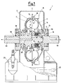
- the fluid coupling of emptying type consists essentially of an outer casing 2 housing two impellers 3 and 4, known respectively as the pump and turbine, which can rotate independently of each other about the same axis X-X. Coaxial with this axis are the shaft 50, driven generally by an electric motor and connected to the pump 3, and the exit shaft 60, which is fixed to the turbine 4 and is connected to a user apparatus.
- the pump 3 rotates an opposing shell 5, the purpose of which is to create a sealed box housing the turbine 4.
- the pump 3 and turbine 4 provided in known manner with respective radial blades, directly face each other to define between them a cavity 7 into which the operating fluid is fed to act as an intermediary between said members, and rotate the turbine at a lower speed than the pump, the speed difference depending on the resistance offered by the user apparatus and the degree of filling of the cavity 7.
- the vorticose movement of the fluid within the cavity expressed indicatively by the arrows 8, 8', results in a power loss and an increase in the fluid temperature.
- the operating fluid consisting of an oil
- the operating fluid is fed in through an inlet connector 10 and leaves in a position radially internal to the impellers 3 and 4, indicated by the arrow 11, to feed the coupling.
- a branch 14 leads the same oil to a rapid discharge valve 16 of known type.
- the valve 16 opens to allow rapid discharge of the oil, which during the operation of the coupling partly escapes continuously through sized holes 18 formed peripherally in the shell 5, as indicated by the arrows 19.
- the oil which collects on the bottom 20 of the casing 2 is fed by a pump 23 to a cooling circuit 24, and after filtration in 25 is returned to circulation by the pump 27.
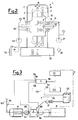
- the coupling is provided with a feed pump 27 with a delivery rate continuously controllable in accordance with a regular diagram.
- a variable rate pump driven by a fixed motor can be used, or alternatively a pump the delivery rate of which is a function of its r.p.m., such as a gear pump, driven by a fixed speed electric motor in series with a variable speed drive of any kind, or again according to a preferred alternative the pump can be driven directly by a variable speed electric motor the rotation speed of which is regulated by a frequency converter.
- the frequency converter can be controlled manually from a control panel C which shows the speed of the exit shaft 60, or can be controlled automatically.
- a microprocessor D is used, which with reference to Figure 3 comprises:
- the microprocessor also has the following inputs:
- the microprocessor acts by controlling the frequency converter 122 for the motor 124 of the feed pump 27 via the line 120 on the basis of the processing of the arriving signals 104 and 108 representing the speeds of the shafts 50 and 60 respectively, and controlling the pump 29 of a separate engagement and disengagement circuit for the shafts 50 and 60 via the line 130, as described hereinafter.
- a means is provided for connecting the shafts together, this means being located advantageously, and as never before, within the coupling itself leading to a substantial saving in the manufacturing cost and overall size of the coupling.
- the means for coupling the shafts together consists of a clutch comprising friction discs 33, 32 fixed alternately to the exit shaft 60 and to a flange 34 rigid with the entry shaft 50 respectively.
- the friction discs are engaged by the thrust of a ring piston 36 operated by pressurized oil of the type used in the operating circuit, and fed through a separate circuit.
- the oil, pressurized by the independent pump 29 ( Figure 2), enters the coupling through an entry connector 38, follows the path 39, 39', 39'' within the shaft 60 and enters the thrust chamber 40 for said ring piston 36, to connect the coupling shafts together as stated.
- interrupting the operation of the pump 29 when the shafts 50 and 60 have been connected together very rapidly removes the thrust from the pack of friction discs 32, 33, to disengage the motor A from the user B with a rapidity not currently attainable with known devices.
- the microprocessor activates the friction clutch via the line 130 following processing of the signals fed by the transducers 105 and 109, to start the pump 29, or to stop it on receipt by the input 100 of a signal representing excess current in the motor A, hence halting the pump.
- a fluid coupling of the type described and illustrated can be used in the most varied ways, including for example:
- the fluid coupling with continuous flow control of the operating fluid may also comprise the internal device for direct connection between the entry and exit shaft, this being particularly useful if the user apparatus can run at the same working speed as the motor, for example when used for operating fans, electrical generator units, belt conveyors, etc.
Landscapes
- Engineering & Computer Science (AREA)
- General Engineering & Computer Science (AREA)
- Mechanical Engineering (AREA)
- Control Of Non-Positive-Displacement Pumps (AREA)
- Control Of Positive-Displacement Pumps (AREA)
- Control Of Fluid Gearings (AREA)
- Loading And Unloading Of Fuel Tanks Or Ships (AREA)
Applications Claiming Priority (2)
| Application Number | Priority Date | Filing Date | Title |
|---|---|---|---|
| ITMI910977 | 1991-04-09 | ||
| ITMI910977A IT1246576B (it) | 1991-04-09 | 1991-04-09 | Giunto idrodinamico del tipo a svuotamento con regolazione continua della portata del fluido immesso nel circuito operativo, con o senza sistema interno di accoppiamento diretto tra albero motore e condotto. |
Publications (2)
| Publication Number | Publication Date |
|---|---|
| EP0508528A1 true EP0508528A1 (de) | 1992-10-14 |
| EP0508528B1 EP0508528B1 (de) | 1995-06-21 |
Family
ID=11359507
Family Applications (1)
| Application Number | Title | Priority Date | Filing Date |
|---|---|---|---|
| EP92200935A Expired - Lifetime EP0508528B1 (de) | 1991-04-09 | 1992-04-02 | Entleerende Flüssigkeitskupplung mit kontinuierlicher Steuerung der Flüssigkeitsmenge zur Speisung des Arbeitsraums, mit oder ohne interner Vorrichtung zum Direktverbinden der treibenden und getriebenen Welle |
Country Status (3)
| Country | Link |
|---|---|
| EP (1) | EP0508528B1 (de) |
| DE (1) | DE69203020T2 (de) |
| IT (1) | IT1246576B (de) |
Cited By (8)
| Publication number | Priority date | Publication date | Assignee | Title |
|---|---|---|---|---|
| DE4342103A1 (de) * | 1993-12-10 | 1995-06-14 | Babcock Prozessautomation Gmbh | Vorrichtung zum Regeln einer Strömungskupplung |
| US5426939A (en) * | 1993-06-28 | 1995-06-27 | Cottrell; Harold L. | Torque converter having automatic power control |
| WO2000055519A1 (de) * | 1999-03-12 | 2000-09-21 | Voith Turbo Gmbh & Co. Kg | Anfahreinheit |
| US6179310B1 (en) | 1996-12-14 | 2001-01-30 | Rover Group Limited | Vehicle roll stabilizing system |
| WO2002046634A3 (en) * | 2000-12-04 | 2003-09-25 | Ebara Corp | Fluid coupling |
| DE102005050736A1 (de) * | 2005-10-22 | 2007-04-26 | Voith Turbo Gmbh & Co. Kg | Hydrodynamische Kupplung |
| WO2011045199A1 (de) * | 2009-10-13 | 2011-04-21 | Zf Friedrichshafen Ag | Nasslaufende kupplungsanordnung |
| CN115159212A (zh) * | 2022-05-25 | 2022-10-11 | 内蒙古联晟新能源材料有限公司 | 一种柔性可调张力的废边拖拽机 |
Families Citing this family (2)
| Publication number | Priority date | Publication date | Assignee | Title |
|---|---|---|---|---|
| US8695434B2 (en) * | 2012-01-31 | 2014-04-15 | Hammonds Technical Services, Inc. | Fluid additive delivery system powered by the flowing fluid |
| DE102020102573A1 (de) | 2020-02-03 | 2021-08-05 | Voith Patent Gmbh | Hydrodynamische Kupplung mit Überbrückungskupplung |
Citations (4)
| Publication number | Priority date | Publication date | Assignee | Title |
|---|---|---|---|---|
| FR69853E (fr) * | 1952-03-22 | 1959-01-09 | Voith Gmbh J M | Accouplement hydraulique |
| DE1750761A1 (de) * | 1967-10-06 | 1971-02-18 | Voith Getriebe Kg | Regelkreislauf fuer eine fuellungsregelbare Stroemungskupplung |
| FR2346601A1 (fr) * | 1976-04-03 | 1977-10-28 | Voith Getriebe Kg | Accouplement hydrodynamique |
| FR2573151A1 (fr) * | 1984-11-14 | 1986-05-16 | Voith Turbo Kg | Circuit hydraulique pour organe de couplage hydrodynamique |
-
1991
- 1991-04-09 IT ITMI910977A patent/IT1246576B/it active IP Right Grant
-
1992
- 1992-04-02 DE DE69203020T patent/DE69203020T2/de not_active Expired - Fee Related
- 1992-04-02 EP EP92200935A patent/EP0508528B1/de not_active Expired - Lifetime
Patent Citations (4)
| Publication number | Priority date | Publication date | Assignee | Title |
|---|---|---|---|---|
| FR69853E (fr) * | 1952-03-22 | 1959-01-09 | Voith Gmbh J M | Accouplement hydraulique |
| DE1750761A1 (de) * | 1967-10-06 | 1971-02-18 | Voith Getriebe Kg | Regelkreislauf fuer eine fuellungsregelbare Stroemungskupplung |
| FR2346601A1 (fr) * | 1976-04-03 | 1977-10-28 | Voith Getriebe Kg | Accouplement hydrodynamique |
| FR2573151A1 (fr) * | 1984-11-14 | 1986-05-16 | Voith Turbo Kg | Circuit hydraulique pour organe de couplage hydrodynamique |
Non-Patent Citations (1)
| Title |
|---|
| PATENT ABSTRACTS OF JAPAN vol. 11, no. 14 (M-553)(2461) 14 January 1987 & JP-A-61 189 330 ( TOYOTA MOTOR CORPORATION ) 23 August 1986 * |
Cited By (14)
| Publication number | Priority date | Publication date | Assignee | Title |
|---|---|---|---|---|
| US5426939A (en) * | 1993-06-28 | 1995-06-27 | Cottrell; Harold L. | Torque converter having automatic power control |
| DE4342103A1 (de) * | 1993-12-10 | 1995-06-14 | Babcock Prozessautomation Gmbh | Vorrichtung zum Regeln einer Strömungskupplung |
| US6179310B1 (en) | 1996-12-14 | 2001-01-30 | Rover Group Limited | Vehicle roll stabilizing system |
| WO2000055519A1 (de) * | 1999-03-12 | 2000-09-21 | Voith Turbo Gmbh & Co. Kg | Anfahreinheit |
| CN100351549C (zh) * | 2000-12-04 | 2007-11-28 | 株式会社荏原制作所 | 液力联轴器 |
| WO2002046634A3 (en) * | 2000-12-04 | 2003-09-25 | Ebara Corp | Fluid coupling |
| US7014021B2 (en) | 2000-12-04 | 2006-03-21 | Ebara Corporation | Fluid coupling |
| DE102005050736A1 (de) * | 2005-10-22 | 2007-04-26 | Voith Turbo Gmbh & Co. Kg | Hydrodynamische Kupplung |
| WO2011045199A1 (de) * | 2009-10-13 | 2011-04-21 | Zf Friedrichshafen Ag | Nasslaufende kupplungsanordnung |
| CN104033509A (zh) * | 2009-10-13 | 2014-09-10 | Zf腓特烈斯哈芬股份公司 | 湿式运转的离合器装置 |
| US8893867B2 (en) | 2009-10-13 | 2014-11-25 | Zf Friedrichshafen Ag | Wet clutch arrangement |
| US9284992B2 (en) | 2009-10-13 | 2016-03-15 | Zf Friedrichshafen Ag | Wet clutch arrangement |
| CN104033509B (zh) * | 2009-10-13 | 2016-09-07 | Zf腓特烈斯哈芬股份公司 | 湿式运转的离合器装置 |
| CN115159212A (zh) * | 2022-05-25 | 2022-10-11 | 内蒙古联晟新能源材料有限公司 | 一种柔性可调张力的废边拖拽机 |
Also Published As
| Publication number | Publication date |
|---|---|
| ITMI910977A1 (it) | 1992-10-09 |
| DE69203020T2 (de) | 1995-12-14 |
| DE69203020D1 (de) | 1995-07-27 |
| IT1246576B (it) | 1994-11-24 |
| ITMI910977A0 (it) | 1991-04-09 |
| EP0508528B1 (de) | 1995-06-21 |
Similar Documents
| Publication | Publication Date | Title |
|---|---|---|
| US4597481A (en) | Hydrodynamic control coupling | |
| US4776163A (en) | Gas turbine power unit | |
| EP0508528B1 (de) | Entleerende Flüssigkeitskupplung mit kontinuierlicher Steuerung der Flüssigkeitsmenge zur Speisung des Arbeitsraums, mit oder ohne interner Vorrichtung zum Direktverbinden der treibenden und getriebenen Welle | |
| US4743776A (en) | Starter-generator for engines | |
| US6993902B2 (en) | Fluid coupling for mobile equipment | |
| US4581892A (en) | Adjustable fluid coupling | |
| US3020719A (en) | Variable slip fluid coupling | |
| CN107314094B (zh) | 一种无级调速及停机制动的后置减速液力传动装置 | |
| US4671061A (en) | Scoop-controlled fluid couplings | |
| CA1125092A (en) | Power conserving inducer | |
| US2372326A (en) | Fluid drive fob compressors | |
| US3961859A (en) | Clutch connected multi-stage impeller pump | |
| EP1364139B1 (de) | Strömungskupplung | |
| US3505908A (en) | Transmission unit | |
| US3295646A (en) | Centrifugally operated fluid clutch | |
| US3724209A (en) | Fluid unit with dump and fill control | |
| US2873831A (en) | Power transmission systems embodying hydraulic turbo-transmitters | |
| EP1341613B1 (de) | Anordnung und steuerung einer brechanlage | |
| US3785155A (en) | Hydrodynamic unit with auxiliary rotor | |
| US3045432A (en) | Fluid coupling | |
| US3237408A (en) | Variable speed hydrokinetic coupling | |
| US3774400A (en) | Charging pressure control for fluid unit | |
| JP2003156124A (ja) | 流体継手 | |
| SU727161A3 (ru) | Гидродинамическа муфта | |
| SU425007A1 (ru) | Пуско-тормозная проточная гидродинамическая муфта |
Legal Events
| Date | Code | Title | Description |
|---|---|---|---|
| PUAI | Public reference made under article 153(3) epc to a published international application that has entered the european phase |
Free format text: ORIGINAL CODE: 0009012 |
|
| AK | Designated contracting states |
Kind code of ref document: A1 Designated state(s): DE FR GB |
|
| 17P | Request for examination filed |
Effective date: 19930402 |
|
| 17Q | First examination report despatched |
Effective date: 19940318 |
|
| GRAA | (expected) grant |
Free format text: ORIGINAL CODE: 0009210 |
|
| AK | Designated contracting states |
Kind code of ref document: B1 Designated state(s): DE FR GB |
|
| REF | Corresponds to: |
Ref document number: 69203020 Country of ref document: DE Date of ref document: 19950727 |
|
| ET | Fr: translation filed | ||
| PLBE | No opposition filed within time limit |
Free format text: ORIGINAL CODE: 0009261 |
|
| STAA | Information on the status of an ep patent application or granted ep patent |
Free format text: STATUS: NO OPPOSITION FILED WITHIN TIME LIMIT |
|
| 26N | No opposition filed | ||
| PGFP | Annual fee paid to national office [announced via postgrant information from national office to epo] |
Ref country code: GB Payment date: 19990401 Year of fee payment: 8 |
|
| PGFP | Annual fee paid to national office [announced via postgrant information from national office to epo] |
Ref country code: FR Payment date: 19990409 Year of fee payment: 8 Ref country code: DE Payment date: 19990409 Year of fee payment: 8 |
|
| PG25 | Lapsed in a contracting state [announced via postgrant information from national office to epo] |
Ref country code: GB Free format text: LAPSE BECAUSE OF NON-PAYMENT OF DUE FEES Effective date: 20000402 |
|
| GBPC | Gb: european patent ceased through non-payment of renewal fee |
Effective date: 20000402 |
|
| PG25 | Lapsed in a contracting state [announced via postgrant information from national office to epo] |
Ref country code: FR Free format text: LAPSE BECAUSE OF NON-PAYMENT OF DUE FEES Effective date: 20001229 |
|
| PG25 | Lapsed in a contracting state [announced via postgrant information from national office to epo] |
Ref country code: DE Free format text: LAPSE BECAUSE OF NON-PAYMENT OF DUE FEES Effective date: 20010201 |
|
| REG | Reference to a national code |
Ref country code: FR Ref legal event code: ST |