EP0508675A1 - Procédé de mesure de corrélation de débit à grande vitesse par ultrasons utilisant les impulsions codées - Google Patents
Procédé de mesure de corrélation de débit à grande vitesse par ultrasons utilisant les impulsions codées Download PDFInfo
- Publication number
- EP0508675A1 EP0508675A1 EP19920302881 EP92302881A EP0508675A1 EP 0508675 A1 EP0508675 A1 EP 0508675A1 EP 19920302881 EP19920302881 EP 19920302881 EP 92302881 A EP92302881 A EP 92302881A EP 0508675 A1 EP0508675 A1 EP 0508675A1
- Authority
- EP
- European Patent Office
- Prior art keywords
- pulse
- pulses
- recited
- coded pulses
- positive
- Prior art date
- Legal status (The legal status is an assumption and is not a legal conclusion. Google has not performed a legal analysis and makes no representation as to the accuracy of the status listed.)
- Granted
Links
- 238000002604 ultrasonography Methods 0.000 title claims abstract description 25
- 238000005259 measurement Methods 0.000 title claims abstract description 20
- 238000000034 method Methods 0.000 claims description 10
- 230000003111 delayed effect Effects 0.000 claims description 5
- 238000001514 detection method Methods 0.000 claims description 2
- 210000004369 blood Anatomy 0.000 abstract description 12
- 239000008280 blood Substances 0.000 abstract description 12
- 238000002592 echocardiography Methods 0.000 abstract description 9
- 238000001228 spectrum Methods 0.000 description 12
- 238000012546 transfer Methods 0.000 description 8
- 230000017531 blood circulation Effects 0.000 description 4
- 230000000875 corresponding effect Effects 0.000 description 4
- 230000007423 decrease Effects 0.000 description 4
- 230000000694 effects Effects 0.000 description 4
- 210000004204 blood vessel Anatomy 0.000 description 3
- 238000003384 imaging method Methods 0.000 description 3
- 230000003247 decreasing effect Effects 0.000 description 2
- 238000010586 diagram Methods 0.000 description 2
- 230000002093 peripheral effect Effects 0.000 description 2
- 238000012545 processing Methods 0.000 description 2
- 238000012935 Averaging Methods 0.000 description 1
- 230000005540 biological transmission Effects 0.000 description 1
- 210000000601 blood cell Anatomy 0.000 description 1
- 239000002131 composite material Substances 0.000 description 1
- 230000002596 correlated effect Effects 0.000 description 1
- 210000003743 erythrocyte Anatomy 0.000 description 1
- 238000001914 filtration Methods 0.000 description 1
- 238000012986 modification Methods 0.000 description 1
- 230000004048 modification Effects 0.000 description 1
- 230000035515 penetration Effects 0.000 description 1
- 238000005316 response function Methods 0.000 description 1
- 238000005070 sampling Methods 0.000 description 1
- 238000000926 separation method Methods 0.000 description 1
- 230000036962 time dependent Effects 0.000 description 1
- 230000002792 vascular Effects 0.000 description 1
Images


Classifications
-
- G—PHYSICS
- G01—MEASURING; TESTING
- G01F—MEASURING VOLUME, VOLUME FLOW, MASS FLOW OR LIQUID LEVEL; METERING BY VOLUME
- G01F1/00—Measuring the volume flow or mass flow of fluid or fluent solid material wherein the fluid passes through a meter in a continuous flow
- G01F1/66—Measuring the volume flow or mass flow of fluid or fluent solid material wherein the fluid passes through a meter in a continuous flow by measuring frequency, phase shift or propagation time of electromagnetic or other waves, e.g. using ultrasonic flowmeters
-
- A—HUMAN NECESSITIES
- A61—MEDICAL OR VETERINARY SCIENCE; HYGIENE
- A61B—DIAGNOSIS; SURGERY; IDENTIFICATION
- A61B8/00—Diagnosis using ultrasonic, sonic or infrasonic waves
- A61B8/06—Measuring blood flow
-
- G—PHYSICS
- G01—MEASURING; TESTING
- G01F—MEASURING VOLUME, VOLUME FLOW, MASS FLOW OR LIQUID LEVEL; METERING BY VOLUME
- G01F1/00—Measuring the volume flow or mass flow of fluid or fluent solid material wherein the fluid passes through a meter in a continuous flow
- G01F1/704—Measuring the volume flow or mass flow of fluid or fluent solid material wherein the fluid passes through a meter in a continuous flow using marked regions or existing inhomogeneities within the fluid stream, e.g. statistically occurring variations in a fluid parameter
- G01F1/708—Measuring the time taken to traverse a fixed distance
- G01F1/7082—Measuring the time taken to traverse a fixed distance using acoustic detecting arrangements
-
- G—PHYSICS
- G01—MEASURING; TESTING
- G01S—RADIO DIRECTION-FINDING; RADIO NAVIGATION; DETERMINING DISTANCE OR VELOCITY BY USE OF RADIO WAVES; LOCATING OR PRESENCE-DETECTING BY USE OF THE REFLECTION OR RERADIATION OF RADIO WAVES; ANALOGOUS ARRANGEMENTS USING OTHER WAVES
- G01S15/00—Systems using the reflection or reradiation of acoustic waves, e.g. sonar systems
- G01S15/02—Systems using the reflection or reradiation of acoustic waves, e.g. sonar systems using reflection of acoustic waves
- G01S15/50—Systems of measurement, based on relative movement of the target
- G01S15/58—Velocity or trajectory determination systems; Sense-of-movement determination systems
- G01S15/582—Velocity or trajectory determination systems; Sense-of-movement determination systems using transmission of interrupted pulse-modulated waves and based upon the Doppler effect resulting from movement of targets
-
- G—PHYSICS
- G01—MEASURING; TESTING
- G01S—RADIO DIRECTION-FINDING; RADIO NAVIGATION; DETERMINING DISTANCE OR VELOCITY BY USE OF RADIO WAVES; LOCATING OR PRESENCE-DETECTING BY USE OF THE REFLECTION OR RERADIATION OF RADIO WAVES; ANALOGOUS ARRANGEMENTS USING OTHER WAVES
- G01S15/00—Systems using the reflection or reradiation of acoustic waves, e.g. sonar systems
- G01S15/88—Sonar systems specially adapted for specific applications
- G01S15/89—Sonar systems specially adapted for specific applications for mapping or imaging
- G01S15/8906—Short-range imaging systems; Acoustic microscope systems using pulse-echo techniques
- G01S15/8959—Short-range imaging systems; Acoustic microscope systems using pulse-echo techniques using coded signals for correlation purposes
-
- G—PHYSICS
- G01—MEASURING; TESTING
- G01F—MEASURING VOLUME, VOLUME FLOW, MASS FLOW OR LIQUID LEVEL; METERING BY VOLUME
- G01F1/00—Measuring the volume flow or mass flow of fluid or fluent solid material wherein the fluid passes through a meter in a continuous flow
- G01F1/704—Measuring the volume flow or mass flow of fluid or fluent solid material wherein the fluid passes through a meter in a continuous flow using marked regions or existing inhomogeneities within the fluid stream, e.g. statistically occurring variations in a fluid parameter
- G01F1/708—Measuring the time taken to traverse a fixed distance
- G01F1/712—Measuring the time taken to traverse a fixed distance using auto-correlation or cross-correlation detection means
Definitions
- the present invention relates to an ultrasound flow measurement apparatus and, more particularly, to an ultrasound high velocity flow measurement apparatus using time domain correlation.
- a primary use of ultrasound high velocity flow measurement apparatus is for blood velocity flow measurement and profiling.
- One conventional apparatus is known as an ultrasonic Doppler velocimeter.
- the Doppler velocimeter transducer emits a continuous or pulsed beam of ultrasound generally in the range of 1 to 10 MHz in peripheral and deep-lying vessels.
- the frequency of the returned signal, backscattered from moving red blood cells, is different from the frequency of the signal transmitted.
- the velocity of the blood cells vary across the width of the vessel, and therefore, the Doppler signal is a spectrum rather than a single frequency.
- the Doppler-shift spectrum therefore, depends of the velocity distribution of the blood across the vessel cross-section and the angle between the ultrasound beam and flow direction.
- the method of measurement utilizing the Doppler methodology therefore, is sensitive to components that are parallel to ultrasound beams but are relatively insensitive to flow components that are parallel to the transducer.
- a cross-correlation velocimeter Another conventional apparatus used in performing the blood flow measurement and profiling is known as a cross-correlation velocimeter.
- a single pulse is transmitted to a blood vessel from a transducer and the pulse's echoes are received before a second pulse is transmitted. Normalized cross-correlation is then used to determine a time shift (t 2 -t 1 ) of a segment of the first echo with respect to a similar segment of a second echo of the second transmitted pulse.
- the time difference (t 2 -t 1 ) is determined by cross-correlating segments of two consecutive signals which carry the flow information.
- the pulse repetition interval is set by the depth of the body to the flow. Therefore, the larger the depth, the larger the pulse repetition interval.
- equation (1) illustrates that for a given (t 2 -t 1 ), the larger T PR the smaller the velocity v that can be measured. Furthermore, when the velocity v is high, the larger T PR increases the chances for the signals from two successive signals to be de-correlated. This de-correlation results because either during the time T PR scatterers flow out of the ultrasound beam, or in the case of turbulent flow, due to the random nature of the flow, the scatterers change their relative position and therefore, the signal from two successive signals become de-correlated.
- De-correlation depends on the time repetition interval and the flow velocity. Beam geometry and diameter further play important roles in determining the de-correlation time.
- Fig. 2 illustrates this numerically.
- a pulse repetition time of 200 microseconds is used. This implies that the maximum depth of the vessel has to be less than 150 mm inside the body. With this repetition time, a beam diameter of 1 mm yields a maximum measurable flow velocity of 2 m/s for a vessel that intersects the ultrasound beam at 45°.
- a beam diameter of 1 mm yields a maximum measurable flow velocity of 2 m/s for a vessel that intersects the ultrasound beam at 45°.
- Doppler nor conventional cross-correlation schemes are capable of measuring such velocities.
- the conventional cross-correlation velocimeter discussed above utilizes single, or uncoded, pulses.
- Coded pulses, or frequency modulated pulses with frequencies that increase or decrease with time can be used in ultrasound apparatus.
- Coded pulses historically have been used in radar systems to increase power and decrease noise.
- a ramp-up coded pulse which is a frequency modulated pulse that has a frequency increase with time
- a ramp-down coded pulse which is a frequency modulated pulse that has a frequency decrease with time
- a resultant reflected signal is subsequently decoded utilizing a ramp-down or a ramp-up, respectively, decoding matched filter.
- Utilizing coded pulses increases the signal-to-noise ratio because a matched filter can suppress all signals except the appropriately coded pulse.
- an object of the invention to provide an ultrasound high velocity flow correlation measurement apparatus that can accurately measure the blood flow measurement at high velocities and at large depth simultaneously.
- an ultrasound high velocity flow measurement apparatus using time domain correlation comprises a modulator for producing at least two coded pulses, the at least two codes pulses being separated by a predetermined delay; a transducer for transmitting the at least two coded pulses to a measuring object; a receiver for receiving a returned echo signal from the measuring object; a decoder for decoding the returned echo signal and producing at least two decoded signals being separated by the predetermined delay; and a correlator for cross-correlating the two decoded signals and outputting a velocity profile of the measuring object.
- the present invention uses cross-correlation between consecutive echoes of coded pulses to determine the velocity profile of flowing blood.
- a preferred embodiment of the present invention transmits to the blood, in sequence, a coded pulse increasing in frequency and a coded pulse decreasing in frequency.
- the resultant reflected signals returning from the blood are subsequently separated by decreasing frequency decoding and increasing frequency decoding, respectively.
- the result from the decoding is decoded pulses that can be cross-correlated to determine the velocity profile.
- a method of velocity determination by cross-correlation is based on the fact that inhomogenities in flowing blood give rise to distinctive echo patterns.
- This time change can be evaluated by cross-correlating segments of the echo from pulse 1 with the echo of pulse 2. If a band-limited, RF signal is digitized at a rate greater than the Nyquist rate, cross-correlation can be performed directly.
- E 1 (n ⁇ t) is a sampled data for the first echo and E 2 (n ⁇ t) is a sampled data for the second echo
- these echoes are written as follows where A(n ⁇ t) is a time-dependent amplitude of the echo, f 0 is a carrier frequency, B(n ⁇ t) is a phase and (t 2 -t 1 ) is a time shift:
- E 1 (n ⁇ t) A(n ⁇ t) cos(2 ⁇ f 0 n ⁇ t + ⁇ (n ⁇ t))
- E 2 (n ⁇ t) A(n ⁇ t+t 2 -t 1 ) cos(2 ⁇ f 0 n ⁇ t+t 2 -t 1 ) + ⁇ (n ⁇ t+t 2 -t 1 ))
- the time shift (t 2 -t 1 ) is equal to the value of ⁇ for which Pearson's correlation coefficient P( ⁇ ) is equal to unity.
- N is the number of samples in the segment of the pulse echo that is scattered
- a method of coding the pulses according to a preferred embodiment of the present invention utilizes matched filters.
- Matched filters have two basic characteristics. First, if a signal spectrum is described by S( ⁇ ), a frequency response function of a filter that results in a maximum signal-to-noise ratio at the filter output is the complex conjugate of the spectrum, S*( ⁇ ). Second, if a signal waveform is defined by s(t), where t is time, an impulse response of the filter meeting the first characteristic is s(-t), and the filter output waveform is found by performing the operation:
- the "+" sign indicates that the frequency of the linear-FM matched filter pulse increases linearly with time.
- a frequency spectrum is given approximately by the following expression:
- the frequency spectrum of the matched filter required for the decoding of Equation (9) is therefore of the form: and the decoded signal P LFM (t is found by an inverse Fourier transform of the product S LFM ⁇ ) ⁇ H LFM ⁇ ).
- the decoded signal P LFM (t) is larger than the original signal S LFM (t) by a factor T ⁇ f , which is called the processing gain.
- This gain is usually expressed on the dB scale so that the gain is given as 10 log10(T ⁇ f)dB. This is the factor by which the signal-to-noise ratio of the signal is improved.
- the linear-FM matching filter pulse of Equation (9) shows a frequency increase as a function of time. This will be designated as a positive coded pulse.
- a linear-FM pulse matched filter pulse can be written for which the frequency decreases linearly as a function of time. This will be designated as a negative coded pulse.
- This negative coded pulse has a frequency spectrum given approximately by: and the matched filter required for the decoding of equation (14) has the frequency spectrum:
- the decoded signal P LFM t) is found by a inverse Fourier transducer of the product S LFM ⁇ ) ⁇ H LFM ⁇ ).
- each unmatched waveform is reduced by a factor 1/ ⁇ fT relative to the matched waveform as a result of matched filtration. If both waveforms are incident simultaneously on one of the matched filters, only the corresponding pulse will be transmitted with significant magnitude. This affects a separation of the linear-FM signals.
- Equations (9)-(16) hold for signals transmitted without distortion.
- the decoded signal pulse is an inverse Fourier transform of the product S( ⁇ )H( ⁇ )T( ⁇ ) where T( ⁇ ) is the transfer function of the system. If T( ⁇ ) is significantly different from unity, the decoding will not be optimal. However, coded pulses transmitted by a system having a realistic transfer function can be cross-correlated successfully.
- Figs. 3 and 4 illustrate the effect the transfer function can have on linear-FM coded pulses.
- the system transfer function is assumed to be approximated by a Hamming function.
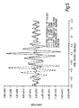
- These figures simulate linear-FM chirp, ultrasound pulses reflected from three stationary point objects.
- the dashed line represents the decoded, negative linear-FM pulse and the solid line represents the decoded, positive linear-FM pulse.
- These illustrations have a discrete sampling interval of 0.03 ⁇ seconds.
- Fig. 3 shows the ideal decoded signals.
- the gain of the matched pulse over the background is about 20 dB. If the pulses were identical, the cross-correlation coefficient match between the two pulses would be perfect and a cross-correlation coefficient would be 1.0. In practice, however, a cross-correlation coefficient above about 0.7 is adequate for determining flow velocity profiles.
- the cross-correlation coefficient between the two pulses in Fig. 3 is about 0.96.
- Fig. 4 shows the signals when a Hamming filter is used to simulate the system transfer function.
- the gain has been reduced to about 17 dB by the mismatch introduced by the Hamming filter.
- the cross-correlation coefficient is still about 0.95.
- a preferred embodiment of the present invention utilizes modified chirp signals, such as a hyperbolic-FM signals S HFM t). These signals have the form:
- the frequency spectra of these waveforms are given by:
- the decoding filters have the form: If a hyperbolic-FM waveform is transmitted and reflected from a moving target, and, if the received signal is decoded in the matched filter, a resulting output signal will contain only the time-shifted term and the phase-shifted term.
- Fig. 5 illustrates the use of the hyperbolic-FM coded pulses.
- the conditions of Fig 4. apply except that the hyperbolic-FM pulses and their matched filters are used instead of the linear-FM pulses.
- the Hamming filter is used to simulate the system transfer function. The gain of the decoded hyperbolic-FM pulses is reduced only a little compared to the decoded linear-FM pulses, and the cross-correlation coefficient is about 0.97.
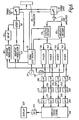
- FIG. 6 A functional block diagram of a preferred embodiment of an ultrasound high velocity flow measurement apparatus using time domain correlation is shown in Fig. 6.
- an oscillator 10 is connected to timing electronics 20, a positive modulator 30, a negative modulator 40, and mixers 130, 140, 150 and 160.
- Timing electronics 20 is connected to a positive modulator 30, a negative modulator 40, a timing gate 70, a timing gate 90, a positive decoder 110 and a negative decoder 120.
- the negative modulator 40 and the positive modulator 30, connected through a delay component 50 are connected to an adder 60 which, in turn, is connected to timing gate 70.
- the signal from timing gate 70 is applied to a transducer 80.
- a signal received from timing gate 90 is sent to the preamplifier 100, which in turn is connected to positive decoder 110 and negative decoder 120.
- Positive decoder 110 is connected to mixers 130 and 140.
- Negative decoder 120 is connected to mixers 150 and 160.
- Mixer 130 is connected to a low pass filter 180
- mixer 140 is connected to a low pass filter 190 and to a shifter 170.
- Mixer 150 is connected to a low pass filter 200
- mixer 160 is connected to a low pass filter 210 and to shifter 170.
- Low pass filters 180, 190, 200 and 210 are connected to A/D converters 220, 230, 240 and 250, respectively.
- A/D converters 220, 230, 240 and 250 are connected to moving target indicators 260, 270, 280 and 290, respectively.
- Moving target indicators 260, 270, 280 and 290 are connected to the input of the complex cross-correlator 300.
- a presently preferred embodiment provides that the output of complex cross-correlator 300 is connected to an averager 310; however, the system can be used without the averager.
- the output of the averager 310 is connected to a display 320.
- the velocimeter of the present invention also can be combined with imaging electronics to produce a duplex system.
- the combining of the velocimeter of the present invention with imaging electronics is considered to be apparent to those skilled in the art.
- a carrier signal is generated by the oscillator 10.
- the carrier signal produces a reference signal used by timing electronics 20, positive modulator 30, negative modulator 40, and mixers 130, 140, 150 and 160.
- Positive modulator 30 produces a positive hyperbolic-FM pulse which corresponds to the (+) form of Equation (17). This pulse is delayed by a time interval ⁇ determined by delay component 50.
- Negative modulator 40 produces a negative hyperbolic-FM pulse which corresponds to the (-) form of Equation (17). The delayed, positive hyperbolic-FM pulse is added to the negative hyperbolic-FM pulse by adder 60.
- both the delayed, positive and the negative hyperbolic-FM coded pulses are passed by timing gate 70 and are applied to transducer 80 and ultimately to the object being measured.
- timing electronics 20 opens timing gate 90, allowing composite echoes comprising echo pulses of both the delayed, positive and the negative coded pulses, to pass into pre-amplifier 100 and then into positive decoder 110 and negative decoder 120.
- Positive decoder 110 effects convolution with a waveform having the frequency spectrum of the (+) form of Equation (19).
- Negative decoder 120 effects convolution with a waveform having the frequency spectrum of the (-) form of Equation (19).
- the output of positive decoder 110 is a compressed pulse of the form of the solid line in Fig. 5.
- the output of negative decoder 120 is a compressed pulse of the form of the dashed line in Fig. 5. These decoded pulses will be separated in time by the interval ⁇ plus any time shift (t 2 -t 1 ) caused by the motion of the targets.
- Both decoded pulses undergo quadrature detection.
- the output from positive decoder 110 is input to both mixer 130 and mixer 140.
- the output from negative decoder 120 is input to both mixer 150 and mixer 160.
- Mixer 130 multiplies the output from positive decoder 110 by the carrier signal produced by oscillator 10 to produce the real part of Equation (5).
- This signal is filtered by low-pass filter 180, sampled by A/D converter 220, passed through moving-target indicator 260 and input to complex cross-correlator 300.
- Mixer 140 multiplies the signal from positive decoder 110 by the phase shifted carrier signal output from shifter 170 to produce the imaginary part of Equation (5).
- This signal is filtered by low-pass filter 190, sampled by A/D converter 230, passed through moving-target indicator 270 and input to complex cross correlator 300.
- Mixer 150 multiples the output from negative decoder 120 by the carrier signal produced by oscillator 10 to produce the real part of Equation (6).
- This signal is filtered by low-pass filter 200, sampled by A/D converter 240, passed through moving-target indicator 280 and input to complex cross correlator 300.
- Mixer 160 multiplies the output from negative decoder 120 by the phase shifted carrier signal output from shifter 170 to produce the imaginary part of Equation (6).
- This signal is filtered by low-pass filter 200, sampled by A/D converter 260, passed through moving-target indicator 290, and input to complex cross-correlator 300.
- the complex cross-correlator 300 outputs the velocity profile given by Equation (1) as a function of depth. This profile passes into averager 310 for averaging, if desired, and then to display 320.
- the present invention may, therefore, be summarized as providing an ultrasound high velocity flow measurement apparatus using cross-correlation between consecutive echoes of coded pulses to determine velocity profiles of flowing blood.
- the interval between at least two coded pulses can be made arbitrarily small, and thus can remove the peak velocity limitation.
- the present invention improves the signal-to-noise ratio over that obtainable by use of uncoded pulses.
Landscapes
- Physics & Mathematics (AREA)
- Engineering & Computer Science (AREA)
- Radar, Positioning & Navigation (AREA)
- Remote Sensing (AREA)
- Acoustics & Sound (AREA)
- General Physics & Mathematics (AREA)
- Health & Medical Sciences (AREA)
- Life Sciences & Earth Sciences (AREA)
- Fluid Mechanics (AREA)
- Computer Networks & Wireless Communication (AREA)
- Nuclear Medicine, Radiotherapy & Molecular Imaging (AREA)
- Medical Informatics (AREA)
- Hematology (AREA)
- Pathology (AREA)
- Radiology & Medical Imaging (AREA)
- Biomedical Technology (AREA)
- Heart & Thoracic Surgery (AREA)
- Biophysics (AREA)
- Molecular Biology (AREA)
- Surgery (AREA)
- Animal Behavior & Ethology (AREA)
- General Health & Medical Sciences (AREA)
- Public Health (AREA)
- Veterinary Medicine (AREA)
- Electromagnetism (AREA)
- Ultra Sonic Daignosis Equipment (AREA)
Applications Claiming Priority (2)
| Application Number | Priority Date | Filing Date | Title |
|---|---|---|---|
| US07/682,515 US5224482A (en) | 1991-04-08 | 1991-04-08 | Ultrasound high velocity flow correlation measurement using coded pulses |
| US682515 | 1991-04-08 |
Publications (2)
| Publication Number | Publication Date |
|---|---|
| EP0508675A1 true EP0508675A1 (fr) | 1992-10-14 |
| EP0508675B1 EP0508675B1 (fr) | 1996-06-19 |
Family
ID=24740039
Family Applications (1)
| Application Number | Title | Priority Date | Filing Date |
|---|---|---|---|
| EP92302881A Expired - Lifetime EP0508675B1 (fr) | 1991-04-08 | 1992-04-02 | Procédé de mesure de corrélation de débit à grande vitesse par ultrasons utilisant les impulsions codées |
Country Status (4)
| Country | Link |
|---|---|
| US (1) | US5224482A (fr) |
| EP (1) | EP0508675B1 (fr) |
| JP (1) | JPH05149963A (fr) |
| DE (1) | DE69211599T2 (fr) |
Cited By (4)
| Publication number | Priority date | Publication date | Assignee | Title |
|---|---|---|---|---|
| WO1999014561A1 (fr) * | 1997-09-15 | 1999-03-25 | Fraunhofer Ges Forschung | Procede et dispositif de mesure des caracteristiques d'ecoulement et d'autres parametres de procede |
| EP0949485A3 (fr) * | 1998-04-07 | 2002-09-11 | Nico Roosnek | Procédé et dispositif pour mesurer des paramètres physiques |
| EP1046928A3 (fr) * | 1999-04-23 | 2004-01-28 | General Electric Company | Méthode et appareil d' imagerie d'écoulement employant excitation codée |
| WO2021239342A1 (fr) * | 2020-05-27 | 2021-12-02 | Robert Bosch Gmbh | Procédé de détermination de la vitesse d'un objet au moyen d'une impulsion ultrasonore |
Families Citing this family (24)
| Publication number | Priority date | Publication date | Assignee | Title |
|---|---|---|---|---|
| US5357964A (en) * | 1993-02-08 | 1994-10-25 | Spivey Brett A | Doppler imaging device |
| US5419331A (en) * | 1994-02-10 | 1995-05-30 | The University Of Rochester | System for estimating target velocity from pulse echoes in response to their correspondence with predetermined delay trajectories corresponding to different distinct velocities |
| US6009046A (en) * | 1995-03-02 | 1999-12-28 | Acuson Corporation | Ultrasonic harmonic imaging system and method |
| US5650571A (en) * | 1995-03-13 | 1997-07-22 | Freud; Paul J. | Low power signal processing and measurement apparatus |
| US5964706A (en) * | 1998-03-18 | 1999-10-12 | General Electric Company | Method and apparatus for pulsed doppler imaging using coded excitation on transmit and pulse compression on receive |
| US5938611A (en) * | 1998-03-26 | 1999-08-17 | General Electric Company | Method and apparatus for color flow imaging using coded excitation with single codes |
| US6213947B1 (en) * | 1999-03-31 | 2001-04-10 | Acuson Corporation | Medical diagnostic ultrasonic imaging system using coded transmit pulses |
| US6241674B1 (en) | 1999-03-31 | 2001-06-05 | Acuson Corporation | Medical ultrasound diagnostic imaging method and system with nonlinear phase modulation pulse compression |
| EP1214910B1 (fr) * | 1999-09-24 | 2005-06-08 | Japan Science and Technology Corporation | Emetteur/recepteur ultrasonore a compression d'impulsions |
| AU7834000A (en) | 1999-09-27 | 2001-04-30 | Ohio University | Determining gas and liquid flow rates in a multi-phase flow |
| EP1146351A1 (fr) * | 2000-04-12 | 2001-10-17 | Bracco Research S.A. | Imagerie de contraste par ultrasons utilisant d'ondes d'excitation des formes doubles |
| JP4698003B2 (ja) * | 2000-07-27 | 2011-06-08 | アロカ株式会社 | 超音波診断装置 |
| GB0030449D0 (en) * | 2000-12-13 | 2001-01-24 | Deltex Guernsey Ltd | Improvements in or relating to doppler haemodynamic monitors |
| US7536043B2 (en) * | 2003-08-18 | 2009-05-19 | Siemens Medical Solutions Usa, Inc. | Flow representation method and system for medical imaging |
| US8372010B2 (en) * | 2004-10-20 | 2013-02-12 | Kabushiki Kaisha Toshiba | Ultrasonic doppler diagnosis device |
| US8328626B2 (en) * | 2005-09-01 | 2012-12-11 | Wms Gaming Inc. | Wagering game with progressive game triggered by multiple players |
| US8100832B2 (en) * | 2007-04-27 | 2012-01-24 | Hitachi Aloka Medical, Ltd. | Ultrasound diagnostic apparatus |
| JP5294295B2 (ja) * | 2007-12-07 | 2013-09-18 | ジーイー・メディカル・システムズ・グローバル・テクノロジー・カンパニー・エルエルシー | 超音波診断装置及び超音波診断治療システム |
| JP5629052B2 (ja) * | 2008-06-03 | 2014-11-19 | 日立アロカメディカル株式会社 | 超音波診断装置 |
| DE102008027489B4 (de) * | 2008-06-10 | 2010-08-19 | Krohne Ag | Akustisches Durchflußmeßgerät |
| JP5654198B2 (ja) * | 2008-06-16 | 2015-01-14 | 日立アロカメディカル株式会社 | 超音波診断装置 |
| EP3052751B1 (fr) | 2013-09-30 | 2019-11-13 | Saudi Arabian Oil Company | Appareil et procédé de production de pétrole et de gaz par effet de flottabilité |
| CN109688935B (zh) | 2016-07-17 | 2022-02-11 | 尼娜医疗有限公司 | 多普勒导向的超声治疗 |
| EP4301236A4 (fr) | 2021-03-04 | 2025-01-08 | Deepsight Technology, Inc. | Imagerie et mesures acoustiques utilisant un chirp à modulation de fréquence non linéaire fenêtré |
Citations (1)
| Publication number | Priority date | Publication date | Assignee | Title |
|---|---|---|---|---|
| EP0312059A1 (fr) * | 1987-10-14 | 1989-04-19 | Matsushita Electric Industrial Co., Ltd. | Appareil diagnostique à ultrasons |
Family Cites Families (4)
| Publication number | Priority date | Publication date | Assignee | Title |
|---|---|---|---|---|
| US3910259A (en) * | 1973-11-23 | 1975-10-07 | Gould Inc | System and method for determining fetal heart rate |
| US4413531A (en) * | 1981-11-13 | 1983-11-08 | The United States Of America As Represented By The United States Department Of Energy | Doppler flowmeter |
| JPS61170442A (ja) * | 1985-01-23 | 1986-08-01 | 松下電器産業株式会社 | 超音波ドツプラ血流装置 |
| JPH062134B2 (ja) * | 1989-09-08 | 1994-01-12 | 株式会社東芝 | 超音波診断装置 |
-
1991
- 1991-04-08 US US07/682,515 patent/US5224482A/en not_active Expired - Fee Related
-
1992
- 1992-04-02 EP EP92302881A patent/EP0508675B1/fr not_active Expired - Lifetime
- 1992-04-02 DE DE69211599T patent/DE69211599T2/de not_active Expired - Fee Related
- 1992-04-03 JP JP4082254A patent/JPH05149963A/ja active Pending
Patent Citations (1)
| Publication number | Priority date | Publication date | Assignee | Title |
|---|---|---|---|---|
| EP0312059A1 (fr) * | 1987-10-14 | 1989-04-19 | Matsushita Electric Industrial Co., Ltd. | Appareil diagnostique à ultrasons |
Non-Patent Citations (1)
| Title |
|---|
| IEEE TRANSACTION ON ULTRASONICS, FERROELECTRICS, AND FREQUENCY CONTROL vol. 37, no. 3, May 1990, NEW YORK, US pages 164 - 175; S.G.FOSTER ET AL: 'Flow Velocity Profile via Time-Domain Correlation: Error Analysis and Computer Simulation' * |
Cited By (4)
| Publication number | Priority date | Publication date | Assignee | Title |
|---|---|---|---|---|
| WO1999014561A1 (fr) * | 1997-09-15 | 1999-03-25 | Fraunhofer Ges Forschung | Procede et dispositif de mesure des caracteristiques d'ecoulement et d'autres parametres de procede |
| EP0949485A3 (fr) * | 1998-04-07 | 2002-09-11 | Nico Roosnek | Procédé et dispositif pour mesurer des paramètres physiques |
| EP1046928A3 (fr) * | 1999-04-23 | 2004-01-28 | General Electric Company | Méthode et appareil d' imagerie d'écoulement employant excitation codée |
| WO2021239342A1 (fr) * | 2020-05-27 | 2021-12-02 | Robert Bosch Gmbh | Procédé de détermination de la vitesse d'un objet au moyen d'une impulsion ultrasonore |
Also Published As
| Publication number | Publication date |
|---|---|
| DE69211599T2 (de) | 1996-10-31 |
| EP0508675B1 (fr) | 1996-06-19 |
| DE69211599D1 (de) | 1996-07-25 |
| US5224482A (en) | 1993-07-06 |
| JPH05149963A (ja) | 1993-06-15 |
Similar Documents
| Publication | Publication Date | Title |
|---|---|---|
| EP0508675B1 (fr) | Procédé de mesure de corrélation de débit à grande vitesse par ultrasons utilisant les impulsions codées | |
| US5938611A (en) | Method and apparatus for color flow imaging using coded excitation with single codes | |
| US5662115A (en) | Method for determining the velocity-time spectrum of blood flow | |
| CN101107539B (zh) | 雷达设备 | |
| US4803990A (en) | Examining moving objects by ultrasound echograpy | |
| US5177691A (en) | Measuring velocity of a target by Doppler shift, using improvements in calculating discrete Fourier transform | |
| US6095977A (en) | Method and apparatus for color flow imaging using Golay-coded excitation on transmit and pulse compression on receive | |
| CN1154162A (zh) | 减轻脉冲多普勒雷达中距离一多普勒模糊的设备和方法 | |
| US5818735A (en) | Method and system for high resolution time-of-flight measurements | |
| WO2020162751A1 (fr) | Système radar à onde continue modulée en fréquence à codage de phase | |
| Cabrera et al. | Development of a practical coherent acoustic Doppler current profiler | |
| US3953823A (en) | Velocity measurement apparatus using pulsed ultrasonic waves | |
| EP0794411A2 (fr) | Mesure d'écoulement | |
| US6758815B2 (en) | Apparatus and method for indicating mechanical stiffness properties of body tissue | |
| Doisy et al. | Target Doppler estimation using wideband frequency modulated signals | |
| US5560363A (en) | Method for calculation of blood velocity and blood velocity spread from multi gated doppler signals | |
| US4155087A (en) | Radar receiver for detecting coded information buried in radar echoes | |
| US5320105A (en) | Ultrasonic echograph for measuring high velocities of blood flows | |
| Kunita et al. | A new method for blood velocity measurements using ultrasound FMCW signals | |
| Waag et al. | Instrumentation for noninvasive cardiac chamber flow rate measurement | |
| US5266956A (en) | Method and device for the measurement of short distances by analysis of the delay in the propagation of a wave | |
| JP2553635B2 (ja) | 超音波ドップラ血流計 | |
| US5669386A (en) | Ultrasonic flow measurement system employing cross-correlation of baseband reflection data | |
| Baek et al. | A new aliasing extension method for ultrasonic 2-dimensional pulsed Doppler systems | |
| JPH06123772A (ja) | 符号化パルスドップラレーダ方式 |
Legal Events
| Date | Code | Title | Description |
|---|---|---|---|
| PUAI | Public reference made under article 153(3) epc to a published international application that has entered the european phase |
Free format text: ORIGINAL CODE: 0009012 |
|
| 17P | Request for examination filed |
Effective date: 19920416 |
|
| AK | Designated contracting states |
Kind code of ref document: A1 Designated state(s): DE NL |
|
| RIN1 | Information on inventor provided before grant (corrected) |
Inventor name: NIKOONAHAD, MEHRDAD Inventor name: SILVERS, ERLVADA ANNE |
|
| 17Q | First examination report despatched |
Effective date: 19950814 |
|
| GRAH | Despatch of communication of intention to grant a patent |
Free format text: ORIGINAL CODE: EPIDOS IGRA |
|
| GRAH | Despatch of communication of intention to grant a patent |
Free format text: ORIGINAL CODE: EPIDOS IGRA |
|
| GRAA | (expected) grant |
Free format text: ORIGINAL CODE: 0009210 |
|
| AK | Designated contracting states |
Kind code of ref document: B1 Designated state(s): DE NL |
|
| REF | Corresponds to: |
Ref document number: 69211599 Country of ref document: DE Date of ref document: 19960725 |
|
| PLBE | No opposition filed within time limit |
Free format text: ORIGINAL CODE: 0009261 |
|
| STAA | Information on the status of an ep patent application or granted ep patent |
Free format text: STATUS: NO OPPOSITION FILED WITHIN TIME LIMIT |
|
| 26N | No opposition filed | ||
| PGFP | Annual fee paid to national office [announced via postgrant information from national office to epo] |
Ref country code: DE Payment date: 20090327 Year of fee payment: 18 Ref country code: NL Payment date: 20090405 Year of fee payment: 18 |
|
| REG | Reference to a national code |
Ref country code: NL Ref legal event code: V1 Effective date: 20101101 |
|
| PG25 | Lapsed in a contracting state [announced via postgrant information from national office to epo] |
Ref country code: NL Free format text: LAPSE BECAUSE OF NON-PAYMENT OF DUE FEES Effective date: 20101101 |
|
| PG25 | Lapsed in a contracting state [announced via postgrant information from national office to epo] |
Ref country code: DE Free format text: LAPSE BECAUSE OF NON-PAYMENT OF DUE FEES Effective date: 20101103 |