EP0508845A2 - Méthode et appareil de traitement d'images - Google Patents
Méthode et appareil de traitement d'images Download PDFInfo
- Publication number
- EP0508845A2 EP0508845A2 EP92400638A EP92400638A EP0508845A2 EP 0508845 A2 EP0508845 A2 EP 0508845A2 EP 92400638 A EP92400638 A EP 92400638A EP 92400638 A EP92400638 A EP 92400638A EP 0508845 A2 EP0508845 A2 EP 0508845A2
- Authority
- EP
- European Patent Office
- Prior art keywords
- image
- pixels
- black
- lines
- pixel
- Prior art date
- Legal status (The legal status is an assumption and is not a legal conclusion. Google has not performed a legal analysis and makes no representation as to the accuracy of the status listed.)
- Granted
Links
Images






Classifications
-
- G—PHYSICS
- G07—CHECKING-DEVICES
- G07C—TIME OR ATTENDANCE REGISTERS; REGISTERING OR INDICATING THE WORKING OF MACHINES; GENERATING RANDOM NUMBERS; VOTING OR LOTTERY APPARATUS; ARRANGEMENTS, SYSTEMS OR APPARATUS FOR CHECKING NOT PROVIDED FOR ELSEWHERE
- G07C9/00—Individual registration on entry or exit
- G07C9/20—Individual registration on entry or exit involving the use of a pass
- G07C9/22—Individual registration on entry or exit involving the use of a pass in combination with an identity check of the pass holder
- G07C9/25—Individual registration on entry or exit involving the use of a pass in combination with an identity check of the pass holder using biometric data, e.g. fingerprints, iris scans or voice recognition
- G07C9/257—Individual registration on entry or exit involving the use of a pass in combination with an identity check of the pass holder using biometric data, e.g. fingerprints, iris scans or voice recognition electronically
-
- G—PHYSICS
- G06—COMPUTING OR CALCULATING; COUNTING
- G06V—IMAGE OR VIDEO RECOGNITION OR UNDERSTANDING
- G06V10/00—Arrangements for image or video recognition or understanding
- G06V10/20—Image preprocessing
- G06V10/34—Smoothing or thinning of the pattern; Morphological operations; Skeletonisation
-
- G—PHYSICS
- G06—COMPUTING OR CALCULATING; COUNTING
- G06V—IMAGE OR VIDEO RECOGNITION OR UNDERSTANDING
- G06V40/00—Recognition of biometric, human-related or animal-related patterns in image or video data
- G06V40/10—Human or animal bodies, e.g. vehicle occupants or pedestrians; Body parts, e.g. hands
- G06V40/12—Fingerprints or palmprints
Definitions
- the present invention relates to an image processing device and a method thereof, wherein, when carrying out pattern recognition on a digitalized image (fingerprints, stamped images, diagrams, letter characters, etc.) through use of an image processing device (hardware/software in a computer, an electronic switching machine, a communication control unit, an IC card, an image recognition device, an image matching device, an image testing device, or the like), the image information for registration use is recorded in a memory device, this image processing device and the method thereof being further utilized to carry out a judgement as to whether or not two images are identical through a comparison of the concordance (concordant match) between the two images.
- an image processing device hardware/software in a computer, an electronic switching machine, a communication control unit, an IC card, an image recognition device, an image matching device, an image testing device, or the like
- a fingerprint is the pattern of the ridges of a finger. Furthermore, because through valley lines (the space between the ridges) are set by ridges, in place of using a pattern showing ridges, it is acceptable to use a pattern showing through valley lines as the fingerprint.
- the lines treated as a fingerprint shall be called "fingerprint lines".
- fingerprint input devices for confirming an individual's identity
- an image pick-up device for example, a CCD (charge coupled device) camera ⁇
- the prism method for example, Shimizu et al., "Entry Method of Fingerprint Image with Prism - Comparison between the Total Reflection Method and Light-Path Separation Method", IECE Journal, Vol. J68-D, No. 3, pp. 414-415 (1985) ⁇
- the hologram method ⁇ for example, Igaki, et al., "Personal Identification Terminal using Holographic Fingerprint Sensor", Institute of Electronics Information and Communication Engineers of Japan (IEICE) Techenical Report, PRU 87-31, pp.
- the fingerprint image of analog information input from an image pick-up device is converted into a gray scale image of a digitalized fingerprint by an analog/digital converter.
- This gray scale image of the fingerprint is indicated by coordinate (X,Y), which is the image memory pixel address, and by the brightness of the pixels, which is a component of each pixel address of image memory.
- the scheme of setting the X and Y axes is freely chosen.
- a fingerprint image may be formed by converting the concavities and convexities of the fingerprint directly into a binary image. Correction can then be carried out on the gray scale image of the fingerprint according to smoothing and using the direction of the ridges. End points, branch points and points of intersection are present as characteristic points which show the distinctive features of a fingerprint.
- the characteristic points of the gray scale image of a digitalized fingerprint can be detected by binarizing a fingerprint image, further thinning it and then detecting whether a pattern identical to the pattern of a region of pixels showing a characteristic point is present in the thinned image ⁇ for example, Sasagawa et al., "Personal Verification System with High Tolerance of Poor Quality Fingerprints", IEICE Journal, Vol. J72-D-II, No. 5, pp. 707-714 (1989) ⁇ .
- the fingerprint for which information has been recorded in memory prior to the time of comparison is called the "registered fingerprint”.
- the fingerprint which is compared for similarity to the registered fingerprint is called the "tested fingerprint”.
- a method utilizing the characteristic points of the fingerprint, a method of utilizing the direction of the ridges, and a method of matching the patterns of the original images of the tested fingerprint to that of the registered fingerprint are known.
- Japanese Patent Application, First Publication, Laid Open No. Sho 63-132386 discloses a comparison method relying on the superimposition of a thinned image of the tested fingerprint and a thinned image of the registered fingerprint as a method of pattern matching of thinned images.
- Smoothing a treatment for decreasing the noise of a fingerprint image, is, for example, recorded in "Handbook of Image Analysis", pp. 538-548, Tokyo University Publishing (1991), Takagi and Shimoda (Eds.), in which there is a local summation averaging filter which uses the values of neighboring pixels of each pixel.
- a majority means from more than half to all, ideally all
- the line widths are set to a width of one pixel.
- Each pixel of each line may be either black or white. In the description which follows below, however, the case where each pixel of each line is black will be described.
- Hilditch's thinning method in which the outer black pixels in a black pixel aggregation are sequentially deleted while the connectivity between black pixels is maintained, is available, among others, as a method of binarizing a gray scale image and carrying out thinning on that binary image.
- a method of creating a binary image by binarizing a light dark image is disclosed among others, for example, in Mori, et al., "Fundamentals of Image Recognition [I])", pp. 65-71, Ohm Corporation (1986).
- Japanese Patent Application, Second Publication, Laid Open No- Sho 58-55548 "A Method for Determining the Center Position of a Figure" discloses a method in which the ridges having gradients of sudden increase are investigated one by one, obtaining the center point.
- a method is disclosed of utilizing the parallel lines of each rectangular area and the number of intersections to approach one by one the center points.
- Narrowization means to reduce the line width of an image.
- Thinning means to reduce the line width of an image to 1 pixel. Thinning is a special case of narrowization.
- An improvement in the accuracy of the comparison, a reduction in the quantity of registered information, etc. have also been taken into account.
- the quantity of processing required for fingerprint line recovery is large, and, in the event that the characteristic points are not clearly defined or are not many in number, carrying out a comparison becomes difficult.
- a comparison method by pattern matching the original images of a registered fingerprint and a tested fingerprint incorrect discrimination can easily occur due to an alteration of the width of the ridges of the fingerprint because of finger pressure, the condition of the dryness of the skin of the finger and the like, at the time when the fingerprint impression is made. Further, the memory quantity required for storage of registered information becomes large.
- FIG. 1 is an example of a fingerprint recognition system.
- a fingerprint which has been input from image input device 2, is processed at image processing device 1.
- Image processing device 1 is provided with an image memory 4 for storing, when necessary, the gray scale image of a fingerprint, the binary image and the image on which a variety of processing steps have been performed.
- Image processing device 1 is further provided with central processing device 5 having one or more central processing units (CPU), and a memory 6 for storing such information as programs, data, and files (data collection).
- CPU central processing units
- Image memory 4 and memory 6 are classifications according to the stored information and can be realized through utilization of the same memory device.
- Image input device 2 is provided with image pick-up device 7.
- A/D converter 3 converts analog information into digital information (here, in the case where using an image input device of the type in which the digital image is directly obtained, an A/D converter is not necessary).
- Each pixel address in image memory 4, where the fingerprint image which is the gray scale image of a digitalized fingerprint is stored, is shown by the X and Y coordinates (X,Y). Pixel address (X,Y) is sometimes indicated as "pixel (X,Y)", or simply "(X,Y)".
- the section of image memory 4 which stores a single image is called the image plane.
- Image memory 4 can hold one or more image planes.
- Each image plane of image memory 4 is constituted of pixels.
- the processing domain which is specified within the domain of this pixel address is processed.
- processing is carried out by either rounding these numbers up or down.
- the value of the pixel value is shown by the degree of brightness. Which section of the brightness becomes a ridge depends upon the processing of the image in image processing device 1, and upon the method of processing of image input device 2.
- image processing device 1 In both cases, processing is possible by presetting in image processing device 1 the brightness characteristics corresponding to the ridges.
- the aggregation of one or more pixels is called a "pixel aggregation”.
- the fingerprint which is input from image input device 2 for entry in memory 6 of image processing device 1 is called the “registered fingerprint”
- the fingerprint which is input from image input device 2 for testing is called the “tested fingerprint”.
- the black pixels or the white pixels may be selected as the preferred pixel to comprise the lines of the fingerprint (either of these may be made to correspond to ridges or valley lines).
- black pixels will be treated as the fingerprint lines.
- Thinning is the process through which a majority of the line widths are set to the width of one pixel.
- the narrowing of some or all of the line widths of a black pixel aggregation so that they are included in an image formed by the black pixels of the original binary image will be called "narrowization processing".
- thinning is one type of narrowization processing.
- line width is defined as the shortest distance (number of pixels) required to travel from an optional point set at one edge of a line to a point at the other edge of the same line, this distance being traveled by crossing through the inner portion of the line. Line width can be set for each position of the edge of a line.
- FIG. 2(a) shows the condition of the image data which is stored in image memory 4.
- the digitalized image (binarized image or gray scale image) obtained from the image which was input from image input device 2 is stored in the image plane of image 10.
- image plane of image 11 past images, for example, are stored and can be utilized in the processing of image 10.
- image 11 may be unnecessary.
- memory 4 may utilize only image 10.
- FIG. 2(b) shows the state of the information stored in memory 6.
- Program and data for realization of the preferred embodiments of the present invention are stored in program and data 12, while, in registered information 13, recorded information for the registered fingerprint image is stored in a file and maintained.
- a symbol value corresponding to the degree of brightness is fixed.
- a gray scale image established by image memory 4 may be binarized and obtained, or a binarized image may be directly established by image memory 4.
- the coordinate axis and the logical origin point of the image stored in image memory 4 may be fixed independently as a position of a pixel of physical memory image 4. While the X axis and the Y axis may be freely set, for the convenience of explanation, the direction of the X axis is from left to right in the horizontal direction (i.e., in the direction of the increasing value of X), and that of the Y axis is from up to down in the vertical direction (i.e., in the direction of the increasing value of Y).
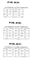
- FIG. 3(a) is an example of a pixel aggregation in which the pixels are arranged in a 3 ⁇ 3 matrix (i.e., 3 pixels ⁇ 3 pixels).
- FIG. 3(b) is an example of a pixel aggregation in which the pixels are arranged in a 4 ⁇ 4 matrix.
- FIG. 3(c) is an example of a pixel aggregation in which the pixels are arranged in a 4 ⁇ 3 matrix.
- FIG. 4 shows an example of the relationship of the fingerprint area determined by fingerprint boundaries, to the portion which samples sub-template RT(0), and to the portion which samples non sub-template RB(0), in image 10 in image memory 4.
- Examples 1-4 are examples of the sub-template portion and the non sub-template portion.
- each means when the subsequent processing is not recorded, the step immediately following is proceeded to.
- the predetermined number utilized in each means is set statically or dynamically to an appropriate value. The realization of each step may be varied provided that the contents of processing are identical.
- Smoothing is the process of decreasing the noise of a fingerprint image. Smoothing processing can be carried out through utilization of a conventional method. (For example, a local summation averaging filter or the like, which utilizes the value of the neighboring pixel of each pixel, may be used).
- Binazation is the process of changing a gray scale image into a binary image.
- Background segregation is the process of clarification of the activated area of the fingerprint image of image 10 in image memory 4.
- An example of a procedure for carrying out binarization and background segregation is given in procedure B below.
- the input information of procedure B is the input information of the image.
- the output information of procedure B is the binary image of the output image and the boundary information of the fingerprint.
- the sub-division addresses for uniquely and clearly discriminating between sub-divisions are defined as an initial pixel address for each sub-division.
- B L and B H are set as the constants for classifying activated and non activated sub-divisions.
- Step B2 (rendering a judgement of "activated" to a sub division)
- the average value of the degree of brightness of the sub-division is again obtained for the binary image resulting from step B1.
- I MN (X/K],[Y/K])
- the sub-division address is the initial address of each sub-division
- X K ⁇ M
- M 0, 1, 2, ...K max
- Y K ⁇ N
- N 0, 1, 2, ...K max
- a judgement of "activated/non-activated" is rendered for each sub-division according to the average value of the degree of brightness Bay(X,Y) obtained from the function of the average value of the degree of brightness for each sub-division.
- Step B3 (Inspection of the number of activated sub-divisions) From G(M,N),
- YT number of activated sub-divisions is counted.
- step B4 is proceeded to.
- YT ⁇ YC due to a shortage error in the number of activated sub-divisions, the present procedure undergoes an error return.
- Step B4 left margin of the fingerprint boundary of a sub-division unit:
- N T N T value
- M L ⁇ M ⁇ M R is the fingerprint area of the sub-division unit.
- the left margin of the fingerprint boundary is obtained for the sub-division unit.
- those elements G(M,N) having an indicator of "1" (indicating an activated sub-division) in table G, which shows the activated sub-divisions are searched for sequentially.
- the value M L of the initial M of a section in which indicators having a "1" value are continuous for Kc (Kc is a predetermined number greater than 1 and used for judging the fingerprint boundaries of the sub-division) indicators or more is set as the left margin of the fingerprint area for the current N.
- Step B5 right margin of the fingerprint boundary for each sub-division:
- the right margin M R of the fingerprint boundary is obtained for each sub-division unit.
- those elements G(M,N) which are indicated by "1" (indicating an activated sub-division) are searched for sequentially.
- Step B6 fingerprint boundary information of each pixel
- X L ⁇ X ⁇ X R is the fingerprint area.
- FIG. 5 is an example of a table showing the activated area of a fingerprint.
- the processing includes,
- the image input timing is judged according to the activated block rate of a small region of image memory 4.
- the activated block rate can be obtained in the same manner as steps B1 ⁇ B3 of procedure B. This procedure is shown in procedure Bs.
- procedure Bs when the ratio of the activated sub-division is below the threshold value, procedure Bs is retested after a set time has elapsed.
- the input information of procedure Bs is the input image information and the limits of the small window area of image memory 4.
- the small window area is the limits included in the limits of image 10 which is used in procedure B. Additionally, in order to reduce processing time the processing limits are made smaller than in procedure B. If the processing time is not a consideration, image 10, which is used in procedure B, may be made the object.
- the output information of procedure B is the confirmation or non-confirmation of image 10. (Procedure Bs)
- the sub-division addresses for clearly distinguishing sub-divisions are set to the initial pixel address of each sub-division.
- T average brightness value of sub-division + D (D is a constant integer, positive, negative or zero)
- (X,Y) of sub-division (M,N) at this time i.e., (X,Y) in the limits of K ⁇ M ⁇ X ⁇ K ⁇ (M + 1) - 1 K ⁇ N ⁇ Y ⁇ K ⁇ (N + 1) - 1 when f(X,Y) ⁇ T, (X,Y) is set to white pixels (or black pixels when an indication of a white-black reversal is present).
- f(X,Y) ⁇ T (X,Y) is set to black pixels (or white pixels when an indication of a white-black reversal
- B L and B H are constants for classifying activated and non-activated sub-divisions.
- Step Bs2 activated sub-division judgement
- the average brightness value of the sub-division is again obtained for the binary image resulting from step Bs2.
- I MN ([X/K], [Y/K]) (the sub-division address is the initial address of each sub-division)
- X K ⁇ M
- M 0, 1, 2, ...K max
- Y K ⁇ N
- N 0, 1, 2, ...K max
- a judgement of "activated/non-activated" is rendered for each sub-division according to the average brightness value Bav(X,Y) obtained from the f(x) of the average brightness of each sub-division.
- Step Bs3 inspection of the number of activated pixels
- YT number of activated sub-divisions within the small window is counted according to G(M,N), and when YT ⁇ YCB (YCB is a constant) the process ends with image input confirmation being possible. When YT ⁇ YCB the process ends with image input confirmation not being possible. (End of procedure Bs)
- the degree to which it is necessary to carry out image correction is determined by the quality of the image. As necessary, omissions or reinforcements are carried out. For example, it is possible to perform such simple corrections to image 10 as the exclusion of aggregations of isolated black pixels (by changing them to white pixels), filling aggregations of isolated white pixels (by changing them to black pixels), etc. according to the neighboring pixel pattern for each pixel within the fingerprint area of the binary image.
- Image correction in the preferred embodiments of the present invention is supplied with the objective of providing an ability to sufficiently carry out narrowization.
- An example is shown in procedure T of the procedure for carrying out such simple corrections to image 10 as the exclusion of aggregations of isolated black pixels (by changing them to white pixels), the filling in of aggregations of isolated white pixels (by changing them to black pixels), etc., according to the neighboring pixel pattern for each pixel within the fingerprint area of the binary image.
- the situation shown applies to the individual processes carried out on a 5 ⁇ 5 pixel aggregation.
- the pixels of a 5 ⁇ 5 pixel aggregation are all either black or white.
- Step TZ 1 P 0 selection
- fingerprint boundary information (Y T , X L , X R )
- P O is within the boundary of the fingerprint.
- P O is outside the boundary of the fingerprint.
- Step TZ 2 removal of an isolated black pixel aggregation:
- Step TZ 3 removal of an isolated white pixel aggregation:
- procedure TZ at steps TZ2 and TZ3, when the pixel which is to be updated already is of the value it is to be updated to, updating is not necessary. However, update may be carried out in order to avoid value confirmation processing.
- procedure Q As a separate step, from the binary image of the fingerprint in image 10, a procedure in order to find the approximate center point of the area of the fingerprint is shown below in procedure Q.
- the input information of procedure Q is the input image information and information of the fingerprint boundary.
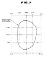
- the output information of procedure QZ is the approximate center point (X c ,Y c ). Each constant, fingerprint area and function of the approximate center point are shown in FIG. 7. (procedure QZ)
- Step OZ 1 (process for obtaining Y c ) :
- the line segment width of each intersecting section of black pixels is set at or above a fixed value (for example, one pixel).
- H D , H U , V L , V R the limits V L ⁇ X ⁇ V R and H D ⁇ Y ⁇ H U are within the fingerprint area and are constant numbers selected so that they become the settable limits of the approximate center point.
- Step QZ 2 (process for obtaining X c ) :
- the line segment width of intersecting sections of black pixels is set to a fixed value (for example, one pixel).
- Restrictions are set to the limits for which an approximate center point is obtained for a fingerprint with an unclear center point.
- the procedure is as follows.
- the limits of the approximate center point can be set to an optional shape and are set to small limits which can be dealt with by comparison processing.
- X CL ⁇ X ⁇ X CH , and Y CL ⁇ Y ⁇ Y CH can be set as the limits.
- the approximate center is set to the value closest to the limits of the approximate center.
- a digital image is, when binarized, shown by black and white pixels.
- the symbol value which is the value of the respective degrees of brightness of the black and white pixels is preset.
- pixels known as "unresolved pixels” a pixel which has not been distinguished as a black or white pixel
- the symbol values with respect to these unresolved pixels are also pre-set.
- FIG.2(a) shows the condition of the image data stored in image memory 4.
- the gray scale image obtained from information input from input device 2 or a binary image (including the situation where a gray scale image is binarized) is stored in image 10 as the original image.
- image 10 is stored in image 10.
- 4-neighbor connected or 8-neighbor connected is used in the connectivity of black pixels of a thinned image. In the embodiments of the present invention, 8-neighbor connected is used for connectivity of black pixels.
- FIG.3(a) shows an abbreviation of a 3 ⁇ 3 pixel aggregation centered about pixel P O .
- the address of P O is set to (X,Y), and the address of P 1 is (X+1,Y), of P 2 is (X+1,Y-1), of P 3 is (X,Y-1), of P 4 is (X-1,Y-1), of P 5 is (X-1,Y), of P 6 is (X-1,Y+1), of P 7 is (X,Y+1), and of P 8 is (X+1,Y+1).
- each parallel line must be only a line passing through each coordinate.
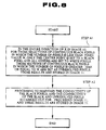
- procedure A An example of the step which, in a binary image, classifies black pixels and white pixels which have undergone thinning processing, from unresolved pixels - pixels for which thinning is unresolved - is shown in procedure A.
- An abbreviation of procedure A is shown is FIG.8.
- each black pixel of the X axis and lines parallel to the X axis is classified as a black pixel, a white pixel or an unresolved pixel.
- original image 10 which is the binary image stored in image memory 4
- the coordinate of the black pixel and the unresolved pixel is set to (X 0 ,Y 0 ) and the following process is carried out.
- step T an unresolved pixel generated by the results of execution of procedure A (in the case of a gray scale image, the results of execution of procedure BZ), and an example of the step of thinning for the Y axis and lines parallel to it is shown.
- step T for unresolved pixels in image 11 for which the processing of step A has been completed, the connectivity to the black pixel which has been connected to the above unresolved pixel is maintained, unresolved pixels are classified from black and white pixels, and a thinned image is produced.
- a summary of step T is shown in FIG.9.
- Step T1
- the pixel of the center point of the interval in which the unresolved pixels are connected in the Y direction is changed to a black pixel or a white pixel.
- processing is carried out starting from the unresolved pixel having the smallest Y coordinate.
- this step the connectivity between the center point in the Y direction of the unresolved pixel aggregation and the black pixels which are adjacent above, below, to the right and to the left (left includes the left horizontal in the upper and lower direction and right includes the right horizontal in the upper and lower direction) of this unresolved pixel aggregation is maintained, and thinning process which changes each unresolved pixel into a black pixel or a white pixel is carried out.
- (X 0 ,Y 0 ) is set to the black pixel of the center in the Y direction of the unresolved pixels
- Step T3
- Steps T1 and T2, which comprise procedure T, are carried out for the interval in the Y direction for which unresolved pixels of a single X are to be connected. Additionally, X is increased and the same process is repeated for all unresolved pixels. (End of procedure T)
- FIG. 10 is an example of an unresolved pixel and its thinning
- FIG. 10(a) shows the thinning of an aggregation of the unresolved pixels resulting from procedure A, and of the black pixels which are to be connected to these.
- FIG. 10(b) shows the result of thinning of unresolved pixels according to procedure T (the dotted line is the outline of the original aggregation of unresolved pixels which do not exist in reality but were noted for the purpose of explanation).
- FIG.11 An example of the thinning decision process for unresolved pixels which is used in step T is shown in the following procedure H.
- central processing device 5 carries out inspection through a relative position given from the table head, without relative position number Q given from the head of the table being stored in the data in image processing device 1.
- An abbreviation of procedure H is shown in FIG.11
- Coordinates (X 0 ,Y) of the unresolved pixel of an initial point and coordinates (X 0 ,Y) of the unresolved pixel of a final point for thinning process image 11 are obtained as input information related to this step.
- all of the pixels from the unresolved pixel of the initial point to the unresolved pixel of the final point must be unresolved pixels.
- the following process is carried out sequentially on P 0 , beginning with the initial point of the unresolved pixel of the center of the pixel aggregation (P 0 ) through the final point in a 3 ⁇ 3 pixel matrix, in the increasing direction of Y and depending on the 8 neighboring pixels.
- a hexadecimal indicator, the region for which Q is obtained is 00 ⁇ FF (in the table in FIG.4, Q becomes the hexadecimal indicator)).
- an optional method ⁇ such as the thinning method of Hilditch (for example "Multi-sided Image Processing and Related Software System Research", Tamura et al., Research Report of Electrotechnical Laboratory), No.835,1984 ⁇ can be appropriately used.
- procedure A when sectionally ignoring connectivity and carrying out approximate thinning, step A2 of procedure A is omitted.
- procedure T when sectionally ignoring connectivity and carrying out approximate thinning, the thinning decision data for an unresolved pixel can be set without giving consideration to the connectivity.
- step BZ An example of the process of classifying the black pixels, the white pixels and the unresolved pixels for which thinning is unresolved, is shown in step BZ for the case where simultaneously carrying out thinning and binarization of a gray scale image and obtaining a thinned image.
- a thinned image is stored in original image 10.
- the differential value may be defined by some other method.
- Step BZ 1
- original image 10 is classified into one or more sub-divisions, and the average brightness value is obtained for each division.
- this step thinning according to an investigation in the X direction, is carried out as follows.
- this step BZ 2 sections other than unresolved pixels are processing in the X direction.
- Aggregations of one or more black pixels are treated as the lines of an image.
- the method of maintaining the designated value of the line width is optional, and both the method of maintaining the designated value of the line width as input information of the narrowization process and the method of maintenance within the narrowization process are possible. It is also possible to maintain one or more designated line width values within a single narrowization processing procedure.
- the procedure of narrowization processing can be appropriately used in response to the designated value of the line width.
- image processing device 1 can be equipped with only a narrowization processing procedure for the designated value of the line width corresponding to the first image and with a narrowization processing procedure corresponding to the second image.
- An example of a narrowization processing procedure which relies on the designated value of the line width follows below
- narrowization can be accomplished through keeping the black pixels below the indicated value of the line width which includes the center of said line segment (in the case where the line segment width is above the indicated value for the line width, the center point of the line segment is set as the center and the black pixels of the indicated value of the line width are kept and all of the black pixels above the line segment for which the line segment width does not satisfy the indicated value of the line width are kept).
- procedure F A concrete example of the procedure is shown in procedure F.
- the situation is disclosed wherein the X axis and lines parallel to it are utilized as one straight line L X and its parallel lines, and the Y axis and lines parallel to it are used as a straight line L Y and its parallel lines, this line L Y forming an angle of a fixed degree greater than 0 degrees with straight line L X (i.e., the turning angle is 90 degrees).
- a parallel line will be only a line which passes through each coordinate.
- the input information of procedure F is the image input information.
- the output information is the output image.
- Step F1 (narrowization processing in the X direction):
- Step F2 (narrowization processing in the Y direction):
- the line width of the image can be expanded.
- the indicated value for line width can be optionally set. However, it is necessary to set the value on the basis of such factors as the quality and characteristics of the input image, the performance with respect to the indicated value for line width in narrowization processing, the performance demanded of image processing device 1, etc.
- the following effects are obtained due to the partial conversion of the black pixels of a registered image (i.e. the pixels to be processed) into white pixels in the limits which have no effect upon the accuracy of the comparison.
- the processing quantity for the comparison decreases due to the decrease of the black pixels of the sub-template portion, and the file quantity of the recorded information decreases.
- the file quantity for the recorded information is decreased due to the decrease of the black pixels of the non sub-template portion. In this step, omission of the comparison of the fingerprint is possible, and, in particular, it is possible to reduce the file quantity and processing quantity when necessary.
- Procedure D is an example of the process to convert black pixels of the registered image into white pixels.
- Step D1 processing in the X direction:
- Step D2 processing in the Y direction:
- the data quantity of recorded information is reduced only by the portion of the black pixels which are converted within the template.
- the quantity of the comparison processing is reduced only by the quantity of the processing to the black pixels converted within the template portion.
- the process of recording fingerprint information involves the process of extracting sub-template RT(0) and non sub-template RB(0) from the registered fingerprint image Rth in image 10, which results from the input, as the registered fingerprint, of image memory 4 to image 10, the carrying out of processing through narrowization processing, and then the storing of template RT(0) and non sub-template RB(0) in each file.
- the steps for carrying out the recording process of the fingerprint information are shown in procedure R.
- the input information of procedure R is the file name of the sub-template and non sub-template of the registered fingerprint, the registered fingerprint image Rth, the fingerprint boundary information of the registered fingerprint and the approximate center point of the registered fingerprint (x RC ,Y RC ).
- the output information of procedure R is the file of the sub-template RT(0) and the file of the non sub-template RB(0).
- Step R1 formation of sub-template RT(0):
- Black pixel addresses within the fingerprint area and in the limits of sub-template RT(0) are extracted from registered fingerprint variable image Rth, and the file of sub-template RT(0) is formed.
- the approximate center point of the registered fingerprint (X RC , Y RC ) is also stored.
- Step R2 formation of non sub-template RB(0)
- a black pixel address which is outside sub-template RT(0) and within fingerprint area FA is extracted from the transposed recorded fingerprint image Rth, and the file of non sub-template RB(0) is formed.
- each file of the sub-template and the non sub-template is optional.
- data may be compressed and stored in a file and, at utilization, data elongation may be carried out.
- Storage memory quantity (Number of black pixels) - ((Memory quantity for x coordinate unit) + (Memory quantity for Y coordinate unit))
- the pixel aggregation recorded herein is for the case of a 3 ⁇ 3 pixel matrix.
- a 3 ⁇ 3 pixel aggregation is shown in FIG. 3(a).
- An example of a part of the image data is shown in FIG.13.
- a representative pixel is set to P 4 and the classification of each pixel as black and white pixels within the pixel aggregation is indicated by bits.
- G P 8
- Representative pixel P 4 is not included in G) the black and white condition of each pixel can be shown by the neighboring pixel code G of 1 byte (hexadecimal digits 00 ⁇ FF).
- Pa is the bit of the surplus of the X coordinate address part, and indicates the classification between the white and black pixels (for example, when the X coordinate address is 1 byte, (X coordinate address/3) is indicated by 7 bits and the classification of white and black pixels of representative pixel P 4 is indicated by other bytes).
- each third X coordinate is set to each third Y coordinate as the representative pixel and a check is made of whether or not there are any black pixels in the 3 ⁇ 3 pixel aggregation (initial point, etc. depends on the setting of the pixel aggregation). Only when black pixels are present are the X coordinate of the representative pixel and the pixel aggregation code memory stored. (For elongation, the opposite process may be carried out).
- a termination sign of the X coordinate values with respect to the value of each Y coordinate may also be added.
- the Y 0 coordinate of the stored X coordinate set number which is equal to zero is packed without being set.
- a 3 ⁇ 3 pixel aggregation in which all of the pixels are white is jumped. Although a 3 ⁇ 3 arrangement is recorded herein for the pixel aggregation, this can be optionally set (for example, 4 ⁇ 4 pixels, 5 ⁇ 3 pixels, etc.).
- the position of the representative pixel within each pixel aggregation can be optionally set.
- an indicator may be added for one of the black/white pixel classification.
- the initial boundary and length (RT(0) and RB(0) in these embodiments) of the image data is set so as to become a three time larger number.
- the X and Y coordinates of the original image are indicated respectively by 1 byte (because it is a binary image it is possible to indicate the degree of brightness by one bit, however, when so doing, the access processing quantity becomes large), and the case where the brightness is stored by one byte is compared to.
- the pixel aggregation recorded herein is for the case of a 4 ⁇ 4 matrix of a pixel aggregation.
- a 4 ⁇ 4 pixel aggregation is shown in FIG. 3 for optional representative pixel P 0 .
- the black and white classification of each pixel is shown by bits.
- a termination sign of the X coordinate values with respect to the value of each Y coordinate may also be added.
- the Y coordinate is stored one time only for only the case where there is a black pixel of the X coordinate (i.e., when the number of sets of stored X coordinates is 0, the Y coordinate is packed without being set).
- a 4 ⁇ 4 pixel arrangement in which all the pixels are white is excluded.
- elongation processing with respect to the compressed registered fingerprint image data, when reading out the file, elongation towards the form of (X,Y) (the opposite process of compression) is carried out. Additionally, the boundary information of the fingerprint is obtained from the right and left margin of the X coordinate value with respect to each Y coordinate value for, for example, the compressed file storage form of RB(0).
- a termination sign of the X coordinate values with respect to the value of each Y coordinate may also be added.
- Comparison processing is the process of checking the concordance of each black pixel of a black pixel aggregation in a image (modified image) of a fingerprint undergoing testing, this fingerprint having been input to image 10 of image memory 4 as a fingerprint to be tested and having undergone all processes through narrowization processing, to each black pixel in a black pixel aggregation which has been stored in memory 6 as recorded information related to a registered fingerprint.
- Narrowed images are called modified images (or fingerprints).
- “narrowed” and “modified” are omitted in many cases.
- Coordinate conversion which relies on rotational and parallel displacements in order to position match a registered fingerprint and a tested fingerprint, can be carried out for either image.
- the set value of the line width of narrowization processing is smaller in the recorded fingerprint for the area within the fingerprint area, the number of black pixels is assumed to become small and the registered image is moved and matched to the image undergoing testing.
- procedure C A procedure for carrying out comparison processing based in the above summary is shown in procedure C.
- the input information of procedure C is the file name of the sub-template and the non sub-template of the registered fingerprint, the image of the fingerprint undergoing testing and the approximate center point of the fingerprint undergoing testing.
- the output information of procedure C is the comparison result.
- Step C1 (comparison using sub-template):
- Step C1 a
- Sub-template RT(0) is stored in memory 6 from the file.
- S Smin ⁇ Smax (incremental value Ks of S)
- H Hmin ⁇ Hmax (incremental value Kh of H)
- V Vmin ⁇ Vmax (incremental value Kv of V)
- Kr Kra (Kra ⁇ 1).
- Step C1 b
- Step C1 c
- Dsd, Dhd and Dvd are predetermined numbers for setting the transposed region.
- step C2 is proceeded to If T1 ⁇ Tk1 the registered fingerprint and the fingerprint undergoing testing are judged to be discordant, and procedure C terminates.
- Step C2 (comparison of the non sub-template) :
- Tk2 if T2 ⁇ Tk2 the registered fingerprint and the fingerprint undergoing testing is judged to be concordant and step C3 is proceeded to. If T2 ⁇ Tk2 the registered fingerprint and the fingerprint undergoing testing are judged to be discordant and procedure C terminates.
- T2 instead of the non sub-template rate of concordance, it is possible to use the template rate of concordance (i.e., (N 1m + N 2m )/(N 1c + N 2c )).
- Step C3 (comparison of discordant sections):
- the discordance of the black pixels of the registered fingerprint and the black pixels of the fingerprint undergoing testing is checked.
- the black pixels in the discordant section of the image of the fingerprint undergoing testing are too many, removal is necessary.
- the following procedure is carried out to approximately obtain and judge the ratio of the black pixels of the discordant section at the point where the line width of the image of the fingerprint undergoing testing has been matched to the image of the registered fingerprint.
- Step C3a
- the approximate region of the area of comparison of the image of the registered fingerprint of ⁇ S,H,V ⁇ is obtained from the region of RT(0) and RB(0).
- the coordinates (X′,Y′) of the region transposed from coordinates (X,Y) is, in the same manner as procedure W, found by the following formula.
- X′ (X-X RC ) ⁇ cos(S) + (Y-Y RC ) ⁇ sin(S) + X TC - H
- Y′ -(X-X RC ) ⁇ sin(S) + (Y-Y RC ) ⁇ cos(S) + Y TC - V
- the cosine and sine functions indicate trigonometric functions.
- Step C3b
- Tnw total number of black pixels in the region of comparison following coordinate conversion of the fingerprint image undergoing testing
- the line width of the image of the fingerprint undergoing testing is set to w and the total number of black pixels Tnc when this line width of the image of the fingerprint undergoing testing is set to the line width of the image of the registered fingerprint (line width ⁇ )
- Tnc Tnw/(w/ ⁇ )
- Tkc (0 ⁇ Tkc ⁇ 1) is a predetermined number indicating the allowable ratio of the number of discordant black pixels of the fingerprint image undergoing testing, the smaller this number being, the stricter the conditions.
- FIG. 14 is an abbreviated flow chart of comparison processing based on procedure C.
- FIG. 15 is a conceptual diagram related to the parameters in step C3.
- FIG. 15 explains the relationship between the discordant sections and the concordant sections of the black pixel aggregation of the modified registered fingerprint image and the black pixel aggregation of the modified image of the fingerprint undergoing testing when the line width of the image of the fingerprint undergoing testing is made concordant to the line width of the modified image of the registered fingerprint.
- Remarks C(1) Each value of the incremental values (Ks,Kh,Kv), which are the incremental widths of the primary translation in step C1a, is checked as large values over comparatively wide limits.
- a narrow value is set to each value of the incremental value (Ksb,Khb,Kvb) which is the increment of secondary translation on step C1b and comparatively small limits, which include the quasi-optimal values of the ⁇ S,H,V ⁇ obtained in step C1a, are checked.
- the width increment of the final row is set to 1
- the number of rows is set through the third row and, at other than the final row, jump processing is possible for those black pixels for which the incremental value K r is set to 2 or above for the search for black pixels of the registered information.
- the translation limits for the search of the first row is set in order to have an effect on the comparison accuracy.
- the quality the larger the incremental value of the translation, the smaller the number of searches becomes.
- the initial line width be thick (Reason: the incremental value can be made large ⁇ .
- the search limits from the second row and on are set by the incremental width of the previous row. If the incremental values from the second row and on is not set smaller than the previous row (below 1/2), no effect is registered for the various rows. In order to absorb the line strain, a thick line width is preferable. Because the errors in recognition decreases when the final line width is fine, the incremental width of the final row is set to 1.
- step C1 (a multi-stage process comprising 3 steps)
- the incremental value of each value of translation can be made larger than 1 (this value is dependent upon the line width of the narrowization of the tested fingerprint image) in the primary and secondary steps
- the quasi-optimal values of S, H, and V which were determined in the prior step are set to the cardinal point in the secondary and tertiary steps, and it is permissible to carry out a comparison within the limits set according to the previous line width, etc.
- the processing quantity of the comparison (approximately proportionate to the position matching search repetition) can be reduced.
- the translation limits of the primary step (Smin ⁇ Smax, etc.) are set according to the largest permissible limits at the time of fingerprint input.
- the following characteristics are present. (1) The larger the translation limits the larger the number of search repetitions. (2) The smaller the incremental value the larger the search repetitions. (3) The increment value at a midway step is set taking into consideration the increment width of the immediately preceding or immediately proceeding step. (4) For steps other than the final step, jump search is possible. (5) When the setting of the translation limits, the incremental value and the jump search is not appropriate, errors in recognition occurs easily.
- step C3 the line width of the modified image of the tested fingerprint is set close to the value for the line width of the modified image of the registered fingerprint, and the rate of discordance of the sections is obtained.
- a summary of an auxiliary procedure for conducting a check on the concordance of two images is as follows.
- the approximate center point (X R ,Y R ) of the registered fingerprint for each pixel address (X R ,Y R ) of the sub-template RT(0) or non sub-template RB(0) of the registered fingerprint is translated in parallel so as to become concordant to the approximate center point (X TC ,Y TC ) of the fingerprint being tested.
- the coordinate axis of the registered fingerprint is rotated and the black pixel (X R @,Y R @) address following transition is checked as to whether or not there are any black pixels within the fingerprint area of the image of the fingerprint undergoing testing, and parallel displacement is again carried out.
- the input information of procedure W is the aggregation of black pixel addresses of the designated portion of the image of the registered fingerprint (either RT(0) or RB(0)), angle degree transposition quantity S of the coordinate axis (smallest value, largest value, incremental value), horizontal displacement H of the coordinate axis of the registered fingerprint (smallest value, largest value, incremental value), vertical displacement V of the coordinate axis of the registered fingerprint (smallest value, largest value, incremental value), the image of the fingerprint undergoing testing and the jump number J of the jump investigation of the black pixels of the registered fingerprint.
- the output information of procedure W is the optimal angle turning angle S about the coordinate axis for the registered fingerprint, the optimal coordinate axial horizontal displacement quantity H, the optimal coordinate axial horizontal displacement quantity V, the number of concordant black pixels Nm of the image of the fingerprint undergoing testing and the image of the registered fingerprint for the designated region (either RT(0) or RB(0)), the total number of black pixels Nc of the image of the registered fingerprint of the designated region and the rate of concordance T.
- black pixels are checked up to a set number, and when the rate of concordance is below a stipulated cut-off value, for the parameter at that time, the processing is terminated midway.
- the similarity ratio is above a stipulated value for decision, the current ⁇ S,H,V ⁇ are judged to be at the optimal value and the following comparison processing may be abbreviated.
- FIG. 16 is an abbreviated flow chart of procedure W.
- Step W1 selection of angle S
- Step W2 (coordinate transposition according to angle S):
- the black pixels of the narrowization image of the inputted registered fingerprint either RT(0) or RB(0)
- the registered information search value i.e., jump number
- the approximate center (X RC ,Y RC ) of the registered fingerprint is rotated S degrees about the coordinate axis of the registered fingerprint and an aggregation of an all black pixel address (X R @,Y R @) of the new registered fingerprint is obtained.
- Step W3 (calculation of the rate of concordance T) :
- Step W3a
- the counter for the number of concordant black pixels Nm and the counter for the total number of black pixels Nc in the registered fingerprint are respectively set to "0" initially.
- step W3c is executed and the ⁇ S,H,V ⁇ at this time are decided as the ⁇ S,H,V ⁇ of the output information.
- step W3 processing identical to step W3 is carried out for each set of ⁇ S,H,V ⁇ , and the rate of concordance is memory stored.
- step W1 is proceeded to.
- step W6 is proceeded to.
- Step W6 (judgement on the largest rate of concordance):
- Tci may be set so that Nci is as large as possible. The larger Tci becomes, the wider the limits for midway abandonment become. There is a considerable effect on the decrease in the quantity of processing required.
- Ncd and Td in step W3b is determined, for example, as follows.
- the value of Ncd is below the Nc which is the Nc with respect to the number of all of the pixels (Nc) of the modified image of the registered fingerprint, and is set to a value near Nc.
- Nc the number of all of the pixels
- Td the value of Td is less than 1 and is set to a value near 1. If the value of Td is made small, while the effect upon the reduction of processing is considerable, errors in recognition occur frequently.
- Registration processing is the process of registering the registration information of a fingerprint in memory 6 of image processing device 1.
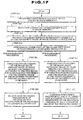
- Comparison processing is the process of judging the concordance of a fingerprint undergoing testing to a registered fingerprint. An abbreviation of the flow from input of the fingerprint through registration or comparison processing is shown in the following procedure Z.
- Steps ZA 1 ⁇ ZA 5 are the in common processes of registration processing and comparison processing.
- Step ZA 1
- Step ZA 2
- Step ZA 3
- Step ZA 4
- Steps ZR 1 ⁇ step ZR 2 are the registration processing and the recording of the registered information of the registered fingerprint in memory 6.
- Step ZR 1
- Narrowization processing within the fingerprint area is carried out on the binary image (primary image) of the registered image in image 10, and a modified image of the registered fingerprint (primary modified image) is obtained.
- Steps ZC 1 ⁇ ZC 2 are for the case of comparison processing, and carry out the comparison of the fingerprint undergoing testing to the registered fingerprint.
- Step ZC 1
- Narrowization is carried out with the fingerprint area of the binarized image of the tested fingerprint (secondary image) in image 10, and a modified image of the fingerprint undergoing testing (secondary modified image) is obtained.
- Step ZC 2
- the present invention is not limited to the above preferred embodiments, but may be expanded upon or altered as follows, for example, without impeding upon the effective utilization of the present invention.
- the claims of the invention of the present application are not intended to be limited by the preferred embodiments of the present invention, and variations or expansions which utilize some other method (i.e., a conventional method), or partial omissions are possible as well.
- the method of setting the X and Y coordinates is optional.
- step W2 of procedure W when the conversion which carries out rotational and parallel displacement is performed, the expression for obtaining X R @ and Y R @ can be utilized.
- the utilization of coordinate transformation or geometric transformation is not limited. The processing quantity necessary for comparison can be reduced due to the supplement of a value for carrying out rotational and parallel displacement of the sub-template as registered information (in this case, the memory quantity increases).
- the present invention can be appropriately applied. Additionally, although in the preferred embodiments of the present invention, the case was presented wherein a single fingerprint to be tested was compared to a single registered fingerprint, the present invention may also be utilized to compare a fingerprint image undergoing testing to two or more registered fingerprints, and from the group of registered fingerprint to find the image with which the tested fingerprint has the greatest rate of concordance.
- the classification of the sub-template and non sub-template is not limited, and expansions such as classifying neither or setting man, classifications are possible.
- the width indicator value of the narrowization processing which is applied to primary image 1 e.g., a registered fingerprint image
- secondary image 2 e.g., a tested fingerprint image
- the complicated image correction processing i.e., correction using line directions
- the line width of the primary image can be set to be less than the line width of the secondary image, in the case where the primary image and the secondary image were obtained from the same object, errors caused by position displacements of the images are reduced.
- the number of black pixels in an image which has undergone narrowization processing are less than the total number of black pixels in the original image, the memory quantity necessary for registered information is less than that required to store as is the original image.
- the processing required for position matching is significantly reduced in comparison to the case when all black pixels of two images are checked, or the entire images, including black and white pixels, are checked. Because it is possible to carry out midway abandonment of a non-utilized comparison in the midway comparison abandonment processing, the processing quantity can be reduced. Further, due to the jump processing of the black pixels of registered information during a comparison, the comparison processing can be decreased.
- the multi-step comparison procedure due to the setting of the quantity of position matching of the image information to the multi-steps, comparison can be carried out through the primary step, which translates image information by a comparatively large translation quantity for comparatively large limits, and by the secondary step, which translates the image information by a comparatively small translation quantity for comparatively small limits, or by the repetition of these. Accordingly, compared to the case where the image information of one image is translated by a small quantity for the entire limits, the complete processing quantity can be decreased.
- the processing quantity for position matching can be decreased more than the utilization of connective sub-template areas. Due to the division and establishment of one or more non sub-template and sub-template areas, the file quantity for registering the non sub-template section can be reduced.
- thinning processing can be carried out rapidly.
- the quantity of registered information of a fingerprint can be reduced. Furthermore, due to the procedure for the partial transformation of a registered image, the registered information quantity of the fingerprint can be reduced and the comparison processing quantity can also be decreased.
Landscapes
- Engineering & Computer Science (AREA)
- Physics & Mathematics (AREA)
- General Physics & Mathematics (AREA)
- Human Computer Interaction (AREA)
- Multimedia (AREA)
- Theoretical Computer Science (AREA)
- Collating Specific Patterns (AREA)
- Image Analysis (AREA)
Applications Claiming Priority (12)
| Application Number | Priority Date | Filing Date | Title |
|---|---|---|---|
| JP4513691A JP2859453B2 (ja) | 1991-03-11 | 1991-03-11 | 画像の細線化方式 |
| JP4513691 | 1991-03-11 | ||
| JP45136/91 | 1991-03-11 | ||
| JP17129891 | 1991-07-11 | ||
| JP3171298A JPH05233782A (ja) | 1991-07-11 | 1991-07-11 | 画像照合方法及び画像照合装置 |
| JP171298/91 | 1991-07-11 | ||
| JP236617/91 | 1991-09-17 | ||
| JP23661791 | 1991-09-17 | ||
| JP3236617A JPH0573686A (ja) | 1991-09-17 | 1991-09-17 | 画像検査装置 |
| JP4033760A JPH05233796A (ja) | 1992-02-20 | 1992-02-20 | 画像処理方法および画像処理装置 |
| JP33760/92 | 1992-02-20 | ||
| JP3376092 | 1992-02-20 |
Publications (3)
| Publication Number | Publication Date |
|---|---|
| EP0508845A2 true EP0508845A2 (fr) | 1992-10-14 |
| EP0508845A3 EP0508845A3 (en) | 1994-05-18 |
| EP0508845B1 EP0508845B1 (fr) | 2001-11-07 |
Family
ID=27459830
Family Applications (1)
| Application Number | Title | Priority Date | Filing Date |
|---|---|---|---|
| EP92400638A Expired - Lifetime EP0508845B1 (fr) | 1991-03-11 | 1992-03-11 | Méthode et appareil de traitement d'images |
Country Status (3)
| Country | Link |
|---|---|
| US (1) | US5537484A (fr) |
| EP (1) | EP0508845B1 (fr) |
| DE (1) | DE69232183T2 (fr) |
Cited By (6)
| Publication number | Priority date | Publication date | Assignee | Title |
|---|---|---|---|---|
| EP0623890A3 (fr) * | 1993-05-07 | 1995-09-06 | Nippon Telegraph & Telephone | Méthode et appareil pour traitement d'images. |
| WO2002003314A1 (fr) * | 2000-07-04 | 2002-01-10 | Casio Computer Co., Ltd. | Appareil et procede de verification d'images |
| US6707934B1 (en) | 1998-12-28 | 2004-03-16 | Casio Computer Co., Ltd. | Apparatus and method for collating image |
| US6718306B1 (en) | 1999-10-21 | 2004-04-06 | Casio Computer Co., Ltd. | Speech collating apparatus and speech collating method |
| US6898301B2 (en) | 2000-07-10 | 2005-05-24 | Casio Computer Co., Ltd. | Authentication system based on fingerprint and electronic device employed for the system |
| WO2017036018A1 (fr) * | 2015-09-02 | 2017-03-09 | 小米科技有限责任公司 | Procédé et appareil d'identification d'empreinte digitale, et terminal mobile |
Families Citing this family (46)
| Publication number | Priority date | Publication date | Assignee | Title |
|---|---|---|---|---|
| US6226032B1 (en) * | 1996-07-16 | 2001-05-01 | General Signal Corporation | Crystal diameter control system |
| US5825923A (en) * | 1996-09-05 | 1998-10-20 | Faxtrieve, Inc. | Method for performing character recognition on a pixel matrix |
| JP3770344B2 (ja) | 1996-12-26 | 2006-04-26 | ソニー株式会社 | 画像照合装置及び画像照合方法 |
| US5917928A (en) * | 1997-07-14 | 1999-06-29 | Bes Systems, Inc. | System and method for automatically verifying identity of a subject |
| US6185316B1 (en) | 1997-11-12 | 2001-02-06 | Unisys Corporation | Self-authentication apparatus and method |
| US7644282B2 (en) | 1998-05-28 | 2010-01-05 | Verance Corporation | Pre-processed information embedding system |
| US6404909B2 (en) * | 1998-07-16 | 2002-06-11 | General Electric Company | Method and apparatus for processing partial lines of scanned images |
| US6737957B1 (en) | 2000-02-16 | 2004-05-18 | Verance Corporation | Remote control signaling using audio watermarks |
| US7236617B1 (en) * | 2000-04-13 | 2007-06-26 | Nanyang Technological University | Method and device for determining a total minutiae template from a plurality of partial minutiae templates |
| JPWO2002029720A1 (ja) * | 2000-09-29 | 2004-02-12 | 中央発條株式会社 | 指紋照合装置及び指紋照合方法 |
| US20020196963A1 (en) * | 2001-02-23 | 2002-12-26 | Biometric Security Card, Inc. | Biometric identification system using a magnetic stripe and associated methods |
| KR100432491B1 (ko) | 2001-08-31 | 2004-05-22 | (주)니트 젠 | 융선방향 모델을 이용한 지문 특징데이터 추출방법 |
| US8601504B2 (en) * | 2002-06-20 | 2013-12-03 | Verance Corporation | Secure tracking system and method for video program content |
| JP4758594B2 (ja) * | 2002-09-24 | 2011-08-31 | セイコーエプソン株式会社 | 入力装置、情報装置及び制御情報生成方法 |
| JP4059047B2 (ja) * | 2002-09-24 | 2008-03-12 | セイコーエプソン株式会社 | 入力装置、情報装置及び制御情報生成方法 |
| CA2499967A1 (fr) | 2002-10-15 | 2004-04-29 | Verance Corporation | Systeme de suivi de media, de gestion et d'information |
| US7616776B2 (en) | 2005-04-26 | 2009-11-10 | Verance Corproation | Methods and apparatus for enhancing the robustness of watermark extraction from digital host content |
| US9055239B2 (en) | 2003-10-08 | 2015-06-09 | Verance Corporation | Signal continuity assessment using embedded watermarks |
| US20060239501A1 (en) | 2005-04-26 | 2006-10-26 | Verance Corporation | Security enhancements of digital watermarks for multi-media content |
| US7369677B2 (en) | 2005-04-26 | 2008-05-06 | Verance Corporation | System reactions to the detection of embedded watermarks in a digital host content |
| JP2005219630A (ja) * | 2004-02-05 | 2005-08-18 | Pioneer Electronic Corp | 操作制御装置、処理制御装置、操作制御方法、そのプログラム、および、そのプログラムを記録した記録媒体 |
| US7421143B2 (en) * | 2004-06-01 | 2008-09-02 | Xerox Corporation | Systems and methods for optimal dynamic range adjustment of scanned images |
| US8020004B2 (en) | 2005-07-01 | 2011-09-13 | Verance Corporation | Forensic marking using a common customization function |
| US8781967B2 (en) | 2005-07-07 | 2014-07-15 | Verance Corporation | Watermarking in an encrypted domain |
| JP2007323500A (ja) * | 2006-06-02 | 2007-12-13 | Sharp Corp | 情報処理装置、方法、プログラムおよびプログラムを記録したコンピュータ読取り可能な記録媒体 |
| JP4844271B2 (ja) * | 2006-07-24 | 2011-12-28 | コニカミノルタビジネステクノロジーズ株式会社 | 画像処理装置及び画像処理方法 |
| JP5031641B2 (ja) * | 2008-03-31 | 2012-09-19 | 富士通株式会社 | パターンの位置合わせ方法、照合方法及び照合装置 |
| US8259938B2 (en) * | 2008-06-24 | 2012-09-04 | Verance Corporation | Efficient and secure forensic marking in compressed |
| US9607131B2 (en) | 2010-09-16 | 2017-03-28 | Verance Corporation | Secure and efficient content screening in a networked environment |
| US8533481B2 (en) | 2011-11-03 | 2013-09-10 | Verance Corporation | Extraction of embedded watermarks from a host content based on extrapolation techniques |
| US8615104B2 (en) | 2011-11-03 | 2013-12-24 | Verance Corporation | Watermark extraction based on tentative watermarks |
| US8682026B2 (en) | 2011-11-03 | 2014-03-25 | Verance Corporation | Efficient extraction of embedded watermarks in the presence of host content distortions |
| US8923548B2 (en) | 2011-11-03 | 2014-12-30 | Verance Corporation | Extraction of embedded watermarks from a host content using a plurality of tentative watermarks |
| US8745403B2 (en) | 2011-11-23 | 2014-06-03 | Verance Corporation | Enhanced content management based on watermark extraction records |
| US9547753B2 (en) | 2011-12-13 | 2017-01-17 | Verance Corporation | Coordinated watermarking |
| US9323902B2 (en) | 2011-12-13 | 2016-04-26 | Verance Corporation | Conditional access using embedded watermarks |
| US9571606B2 (en) | 2012-08-31 | 2017-02-14 | Verance Corporation | Social media viewing system |
| US8726304B2 (en) | 2012-09-13 | 2014-05-13 | Verance Corporation | Time varying evaluation of multimedia content |
| US8869222B2 (en) | 2012-09-13 | 2014-10-21 | Verance Corporation | Second screen content |
| US9106964B2 (en) | 2012-09-13 | 2015-08-11 | Verance Corporation | Enhanced content distribution using advertisements |
| US9262794B2 (en) | 2013-03-14 | 2016-02-16 | Verance Corporation | Transactional video marking system |
| US9251549B2 (en) | 2013-07-23 | 2016-02-02 | Verance Corporation | Watermark extractor enhancements based on payload ranking |
| US9208334B2 (en) | 2013-10-25 | 2015-12-08 | Verance Corporation | Content management using multiple abstraction layers |
| WO2015138798A1 (fr) | 2014-03-13 | 2015-09-17 | Verance Corporation | Acquisition de contenu interactif à l'aide de codes intégrés |
| CN107092852A (zh) * | 2016-02-17 | 2017-08-25 | 北京小米移动软件有限公司 | 压力检测方法和装置 |
| CN114445867B (zh) * | 2022-02-21 | 2024-07-23 | 厦门天马微电子有限公司 | 一种指纹识别器及显示装置 |
Family Cites Families (6)
| Publication number | Priority date | Publication date | Assignee | Title |
|---|---|---|---|---|
| JPS6093577A (ja) * | 1983-10-27 | 1985-05-25 | Fujitsu Ltd | 文字切出し回路 |
| JPS63132386A (ja) * | 1986-11-25 | 1988-06-04 | Dainippon Printing Co Ltd | 指紋照合方法 |
| US5014327A (en) * | 1987-06-15 | 1991-05-07 | Digital Equipment Corporation | Parallel associative memory having improved selection and decision mechanisms for recognizing and sorting relevant patterns |
| CA2004457A1 (fr) * | 1988-12-06 | 1990-06-06 | Seigo Igaki | Extraction de donnees detaillees dans la caracterisation des empreintes digitales |
| JP2702786B2 (ja) * | 1989-08-19 | 1998-01-26 | 富士通株式会社 | 指紋照合装置 |
| KR920002928B1 (ko) * | 1989-11-28 | 1992-04-10 | 한국과학기술연구원 | 지문 인식 방법 |
-
1992
- 1992-03-11 EP EP92400638A patent/EP0508845B1/fr not_active Expired - Lifetime
- 1992-03-11 DE DE69232183T patent/DE69232183T2/de not_active Expired - Fee Related
-
1995
- 1995-04-20 US US08/425,772 patent/US5537484A/en not_active Expired - Fee Related
Cited By (8)
| Publication number | Priority date | Publication date | Assignee | Title |
|---|---|---|---|---|
| EP0623890A3 (fr) * | 1993-05-07 | 1995-09-06 | Nippon Telegraph & Telephone | Méthode et appareil pour traitement d'images. |
| US5825924A (en) * | 1993-05-07 | 1998-10-20 | Nippon Telegraph And Telephone Corporation | Method and apparatus for image processing |
| US6707934B1 (en) | 1998-12-28 | 2004-03-16 | Casio Computer Co., Ltd. | Apparatus and method for collating image |
| US6718306B1 (en) | 1999-10-21 | 2004-04-06 | Casio Computer Co., Ltd. | Speech collating apparatus and speech collating method |
| WO2002003314A1 (fr) * | 2000-07-04 | 2002-01-10 | Casio Computer Co., Ltd. | Appareil et procede de verification d'images |
| US6898301B2 (en) | 2000-07-10 | 2005-05-24 | Casio Computer Co., Ltd. | Authentication system based on fingerprint and electronic device employed for the system |
| WO2017036018A1 (fr) * | 2015-09-02 | 2017-03-09 | 小米科技有限责任公司 | Procédé et appareil d'identification d'empreinte digitale, et terminal mobile |
| US9922228B2 (en) | 2015-09-02 | 2018-03-20 | Xiaomi Inc. | Method and apparatus for fingerprint recognition and mobile terminal |
Also Published As
| Publication number | Publication date |
|---|---|
| EP0508845A3 (en) | 1994-05-18 |
| US5537484A (en) | 1996-07-16 |
| DE69232183D1 (de) | 2001-12-13 |
| EP0508845B1 (fr) | 2001-11-07 |
| DE69232183T2 (de) | 2002-06-20 |
Similar Documents
| Publication | Publication Date | Title |
|---|---|---|
| EP0508845A2 (fr) | Méthode et appareil de traitement d'images | |
| EP0623890A2 (fr) | Méthode et appareil pour traitement d'images | |
| He et al. | Image enhancement and minutiae matching in fingerprint verification | |
| CN100414558C (zh) | 基于模板学习的自动指纹识别系统和方法 | |
| US7035444B2 (en) | System for fingerprint authentication based of ridge shape | |
| KR100299858B1 (ko) | 지문 매칭 방법 | |
| Chiu et al. | A novel stroke-based feature extraction for handwritten Chinese character recognition | |
| Soni et al. | Improved block-based technique using surf and fast keypoints matching for copy-move attack detection | |
| Muzaffer et al. | Copy move forgery detection with quadtree decomposition segmentation | |
| Kumar et al. | FPR using machine learning with multi‐feature method | |
| Sabir | Sensitivity and specificity analysis of fingerprints based algorithm | |
| Agarwal et al. | A utility of ridge contour points in minutiae-based fingerprint matching | |
| Benchaou et al. | New approach of features extraction for numeral recognition | |
| Mamatov et al. | Hybrid quadratic diagonal algorithm for thinning contour lines | |
| Raj et al. | Offline Tamil handwritten character recognition using chain code and zone based features | |
| Tan et al. | Minutiae-based offline palmprint identification system | |
| Mokshith Reddy et al. | Signature Verification using Edge Detection and Oc-Svm | |
| Shen et al. | Feature extraction in fingerprint images | |
| Starzyk et al. | Vector contour representation for object recognition in neural networks | |
| JPS62271190A (ja) | セグメント数字認識方式 | |
| Rakshitha et al. | Latent Fingerprint Enhancement for Investigation | |
| JPH0465776A (ja) | 画像の比較方法 | |
| Chen | Bank card number identification program based on template matching | |
| JPH0495175A (ja) | 指紋照合方法 | |
| Hu et al. | Structural boundary feature extraction for printed character recognition |
Legal Events
| Date | Code | Title | Description |
|---|---|---|---|
| PUAI | Public reference made under article 153(3) epc to a published international application that has entered the european phase |
Free format text: ORIGINAL CODE: 0009012 |
|
| AK | Designated contracting states |
Kind code of ref document: A2 Designated state(s): DE FR GB |
|
| PUAL | Search report despatched |
Free format text: ORIGINAL CODE: 0009013 |
|
| AK | Designated contracting states |
Kind code of ref document: A3 Designated state(s): DE FR GB |
|
| 17P | Request for examination filed |
Effective date: 19941007 |
|
| RAP1 | Party data changed (applicant data changed or rights of an application transferred) |
Owner name: NIPPON TELEGRAPH AND TELEPHONE CORPORATION |
|
| 17Q | First examination report despatched |
Effective date: 19970327 |
|
| GRAG | Despatch of communication of intention to grant |
Free format text: ORIGINAL CODE: EPIDOS AGRA |
|
| RIC1 | Information provided on ipc code assigned before grant |
Free format text: 7G 06K 9/00 A, 7G 06K 9/44 B, 7G 07C 9/00 B |
|
| RIC1 | Information provided on ipc code assigned before grant |
Free format text: 7G 06K 9/00 A, 7G 06K 9/44 B, 7G 07C 9/00 B |
|
| GRAG | Despatch of communication of intention to grant |
Free format text: ORIGINAL CODE: EPIDOS AGRA |
|
| GRAG | Despatch of communication of intention to grant |
Free format text: ORIGINAL CODE: EPIDOS AGRA |
|
| GRAH | Despatch of communication of intention to grant a patent |
Free format text: ORIGINAL CODE: EPIDOS IGRA |
|
| GRAH | Despatch of communication of intention to grant a patent |
Free format text: ORIGINAL CODE: EPIDOS IGRA |
|
| GRAA | (expected) grant |
Free format text: ORIGINAL CODE: 0009210 |
|
| AK | Designated contracting states |
Kind code of ref document: B1 Designated state(s): DE FR GB |
|
| REF | Corresponds to: |
Ref document number: 69232183 Country of ref document: DE Date of ref document: 20011213 |
|
| REG | Reference to a national code |
Ref country code: GB Ref legal event code: IF02 |
|
| ET | Fr: translation filed | ||
| PLBE | No opposition filed within time limit |
Free format text: ORIGINAL CODE: 0009261 |
|
| STAA | Information on the status of an ep patent application or granted ep patent |
Free format text: STATUS: NO OPPOSITION FILED WITHIN TIME LIMIT |
|
| 26N | No opposition filed | ||
| PGFP | Annual fee paid to national office [announced via postgrant information from national office to epo] |
Ref country code: GB Payment date: 20080305 Year of fee payment: 17 |
|
| PGFP | Annual fee paid to national office [announced via postgrant information from national office to epo] |
Ref country code: FR Payment date: 20080311 Year of fee payment: 17 Ref country code: DE Payment date: 20080306 Year of fee payment: 17 |
|
| GBPC | Gb: european patent ceased through non-payment of renewal fee |
Effective date: 20090311 |
|
| REG | Reference to a national code |
Ref country code: FR Ref legal event code: ST Effective date: 20091130 |
|
| PG25 | Lapsed in a contracting state [announced via postgrant information from national office to epo] |
Ref country code: DE Free format text: LAPSE BECAUSE OF NON-PAYMENT OF DUE FEES Effective date: 20091001 |
|
| PG25 | Lapsed in a contracting state [announced via postgrant information from national office to epo] |
Ref country code: GB Free format text: LAPSE BECAUSE OF NON-PAYMENT OF DUE FEES Effective date: 20090311 Ref country code: FR Free format text: LAPSE BECAUSE OF NON-PAYMENT OF DUE FEES Effective date: 20091123 |