EP0509191A2 - Arrangement de détecteur pour cylindre de suspension d'un contrôle d'assiette - Google Patents
Arrangement de détecteur pour cylindre de suspension d'un contrôle d'assiette Download PDFInfo
- Publication number
- EP0509191A2 EP0509191A2 EP92101091A EP92101091A EP0509191A2 EP 0509191 A2 EP0509191 A2 EP 0509191A2 EP 92101091 A EP92101091 A EP 92101091A EP 92101091 A EP92101091 A EP 92101091A EP 0509191 A2 EP0509191 A2 EP 0509191A2
- Authority
- EP
- European Patent Office
- Prior art keywords
- protective tube
- sensor device
- common housing
- suspension cylinder
- tube
- Prior art date
- Legal status (The legal status is an assumption and is not a legal conclusion. Google has not performed a legal analysis and makes no representation as to the accuracy of the status listed.)
- Granted
Links
Images




Classifications
-
- B—PERFORMING OPERATIONS; TRANSPORTING
- B60—VEHICLES IN GENERAL
- B60G—VEHICLE SUSPENSION ARRANGEMENTS
- B60G17/00—Resilient suspensions having means for adjusting the spring or vibration-damper characteristics, for regulating the distance between a supporting surface and a sprung part of vehicle or for locking suspension during use to meet varying vehicular or surface conditions, e.g. due to speed or load
- B60G17/015—Resilient suspensions having means for adjusting the spring or vibration-damper characteristics, for regulating the distance between a supporting surface and a sprung part of vehicle or for locking suspension during use to meet varying vehicular or surface conditions, e.g. due to speed or load the regulating means comprising electric or electronic elements
- B60G17/019—Resilient suspensions having means for adjusting the spring or vibration-damper characteristics, for regulating the distance between a supporting surface and a sprung part of vehicle or for locking suspension during use to meet varying vehicular or surface conditions, e.g. due to speed or load the regulating means comprising electric or electronic elements characterised by the type of sensor or the arrangement thereof
- B60G17/01933—Velocity, e.g. relative velocity-displacement sensors
-
- F—MECHANICAL ENGINEERING; LIGHTING; HEATING; WEAPONS; BLASTING
- F16—ENGINEERING ELEMENTS AND UNITS; GENERAL MEASURES FOR PRODUCING AND MAINTAINING EFFECTIVE FUNCTIONING OF MACHINES OR INSTALLATIONS; THERMAL INSULATION IN GENERAL
- F16F—SPRINGS; SHOCK-ABSORBERS; MEANS FOR DAMPING VIBRATION
- F16F9/00—Springs, vibration-dampers, shock-absorbers, or similarly-constructed movement-dampers using a fluid or the equivalent as damping medium
- F16F9/32—Details
- F16F9/3207—Constructional features
- F16F9/3235—Constructional features of cylinders
- F16F9/3242—Constructional features of cylinders of cylinder ends, e.g. caps
-
- F—MECHANICAL ENGINEERING; LIGHTING; HEATING; WEAPONS; BLASTING
- F16—ENGINEERING ELEMENTS AND UNITS; GENERAL MEASURES FOR PRODUCING AND MAINTAINING EFFECTIVE FUNCTIONING OF MACHINES OR INSTALLATIONS; THERMAL INSULATION IN GENERAL
- F16F—SPRINGS; SHOCK-ABSORBERS; MEANS FOR DAMPING VIBRATION
- F16F9/00—Springs, vibration-dampers, shock-absorbers, or similarly-constructed movement-dampers using a fluid or the equivalent as damping medium
- F16F9/32—Details
- F16F9/38—Covers for protection or appearance
-
- B—PERFORMING OPERATIONS; TRANSPORTING
- B60—VEHICLES IN GENERAL
- B60G—VEHICLE SUSPENSION ARRANGEMENTS
- B60G2202/00—Indexing codes relating to the type of spring, damper or actuator
- B60G2202/40—Type of actuator
- B60G2202/41—Fluid actuator
- B60G2202/413—Hydraulic actuator
-
- B—PERFORMING OPERATIONS; TRANSPORTING
- B60—VEHICLES IN GENERAL
- B60G—VEHICLE SUSPENSION ARRANGEMENTS
- B60G2204/00—Indexing codes related to suspensions per se or to auxiliary parts
- B60G2204/10—Mounting of suspension elements
- B60G2204/11—Mounting of sensors thereon
- B60G2204/112—Mounting of sensors thereon on dampers, e.g. fluid dampers
-
- B—PERFORMING OPERATIONS; TRANSPORTING
- B60—VEHICLES IN GENERAL
- B60G—VEHICLE SUSPENSION ARRANGEMENTS
- B60G2400/00—Indexing codes relating to detected, measured or calculated conditions or factors
- B60G2400/25—Stroke; Height; Displacement
-
- B—PERFORMING OPERATIONS; TRANSPORTING
- B60—VEHICLES IN GENERAL
- B60G—VEHICLE SUSPENSION ARRANGEMENTS
- B60G2400/00—Indexing codes relating to detected, measured or calculated conditions or factors
- B60G2400/25—Stroke; Height; Displacement
- B60G2400/252—Stroke; Height; Displacement vertical
Definitions
- the invention relates to a sensor device for suspension cylinders of a level control, with which it is possible to regulate the position of a vehicle via the distance between a first and a second articulation eye.
- the known generic sensor device (DE-27 34 417 A1) consists of two magnetically responsive reed switches which are designed as sensors and are arranged on a protective tube at a distance from one another in the longitudinal direction of the suspension cylinder.
- the generic sensor device has metal strips which extend the effect of a permanent magnet located in an end area of an outer tube of a suspension cylinder to a wide detection area.
- the magnetically responsive reed switches are arranged on the protective tube made of non-magnetic material with a relatively large distance in the longitudinal direction of the suspension cylinder from one another.
- the protective tube is rigidly connected to the suspension cylinder.
- a signal for the supply or discharge of pressure medium in or from a chamber is generated by the permanent magnet approaching the metal strips connected to the magnetically responsive reed switches, such a signal actuating either a pressure medium pump or a pressure medium outlet valve.
- a disadvantage of the generic sensor device is that different suspension cylinders for different vehicle types have to be manufactured and kept ready, since the sensor device is rigidly connected to the suspension cylinder via the protective tube, and that an adaptation of the sensor device to the suspension cylinder depending on the vehicle type and depending on manufacturing tolerances is not is possible.
- Another known sensor device (DE-35 12 232 C2) has contactless electrical switches as a sensor device, which are arranged on the protective tube of the suspension cylinder.
- the contactless electrical switches cause signals on the approach of the end region of the outer tube of the suspension cylinder, which cause the pressure medium supply or discharge.
- the contactless electrical switches are rigidly connected to the protective tube, the small distance in the longitudinal spring extension of the contactless electrical switches making it necessary to move them in the circumferential direction.
- the invention is therefore based on the object of developing a sensor device in such a way that the above-mentioned disadvantages of the prior art are avoided and that in particular an adjustment of the sensor device depending on different vehicle heights, vehicle and manufacturing tolerances is possible with the same components.
- the object underlying the invention is achieved in a sensor device according to the preamble of the main claim according to the invention by its characterizing features.
- the sensor device has at least a first sensor and a second sensor spaced apart therefrom in the longitudinal direction of the suspension cylinder.
- the first and second sensors are arranged in a common housing, which is detachably and displaceably attached to the protective tube in the longitudinal direction of the suspension cylinder.
- the protective tube is rotatably attached to the suspension cylinder about the longitudinal axis of the suspension cylinder.
- the signal emitted by the sensor causes a pressure medium to be fed into the chamber of the suspension cylinder by the distance between the first and the second articulation eye to enlarge. If, due to changes in the load on the vehicle, the second sensor facing the second pivot eye is run over by the end region of the outer tube of the suspension cylinder, then the signal emanating from this sensor causes a drain valve to open, so that pressure medium is discharged from the chamber by the distance of the Reduce articulation eyes.
- the sensors used which can be designed, for example, as non-contact proximity switches based on magnetic or induction effects, require a certain amount of space for functional reasons, so that setting a switching distance in the longitudinal extension of the suspension cylinder makes it necessary to move these sensors in the circumferential direction.
- the sensors are therefore spaced apart in the common housing both in the circumferential direction and in the longitudinal spring extension.
- the protective tube can either be provided with openings in a manner known per se, or else preferably the common housing and the sensors with radii adapted to the outer wall of the protective tube.
- the configuration of the protective tube with a shoulder and the common housing with a groove which is shown in a further development according to the subclaims, enables the sensor position to be set as a function of the vehicle type and manufacturing tolerances.
- the clamping device provided for holding the common housing serves to hold the common housing on the attachment.
- a further possibility of adjusting the sensor position results from the rotatable design of the protective tube on the suspension cylinder.
- a conical widening on the protective tube is provided on the one end of the protective tube facing the first articulation eye, which allows the protective tube to be fastened to the suspension cylinder with half rings and a clamp.
- the switching distance of the sensors can be determined before the common housing is fixed on the protective tube. Since the switching distance of the sensors is partly in the millimeter range, it is important to determine the switching distance beforehand by positioning the sensors in the common housing.
- the common housing also makes it possible to reduce the installation space required for mounting the suspension cylinder and to arrange only one common connecting cable.
- the protective tube has no openings, so that even if the common housing is inadvertently torn from the protective tube, no dirt can enter through the openings to damage the running surface of the piston rod.
- the sensor position can also be set after the suspension cylinder has been assembled and, if necessary, even after it has been installed, it is no longer necessary to produce and stock different protective tubes and thus different series of suspension cylinders.
- the configuration of the sensor device according to the invention therefore provides a uniform protective tube and thus also ensures more rational production, storage and supply of spare parts, since the suspension cylinders can thereby be handled in large numbers.
- the sensor device 1 shown in FIG. 1 for a suspension cylinder of a level control has a first and a second articulation eye 4, 5. Extending between them is an outer tube 8 and an inner tube 17, the outer tube 8 encompassing the inner tube 17 and being sealed by means of first seals 18 against a first running surface 19 formed on the inner tube 17. An additional seal is provided by means of second seals 20 which seal a chamber 9 in that they rest on a second running surface 21 formed on the inner wall of the outer tube 8.
- the volume in the chamber 9 is variable with the distance between the first and the second articulation eye, the chamber 9 being delimited by the second running surface 21, a first end surface 22 closing the inner tube 17 and a second end surface forming a bottom of the outer tube 8 .
- the outer and inner tubes 8, 17 move relative to one another, so that end regions 7 of the outer tube 8 are also displaced with respect to the first articulation eye. These end regions also run over the regions in which sensors 2, 3 are arranged on a protective tube 6.
- the protective tube 6 is arranged essentially concentrically with the inner and outer tubes 17, 8 and is rotatably attached to the end of the suspension cylinder facing the first articulation eye.
- the protective tube is made of a plastic which only insignificantly impairs the effect of the forces leading to the measurement signals.
- the sensors 2, 3 are arranged in the common housing 10 in such a way that even small switching distances can be measured. For this reason, the sensors are offset in the longitudinal direction of the suspension cylinder and offset in the circumferential direction.
- the common housing 10 surrounds with a groove a projection 12 formed on the protective tube 6. This makes it possible to move the common housing 10 and to adjust the sensor position in the longitudinal extension of the suspension cylinder. The sensor position on the circumference is adjusted by turning the protective tube 6 relative to the suspension cylinder.
- the broken upper part of the suspension cylinder shown in FIG. 2 shows the protective tube, the extension 12 located thereon, which is designed as a guide bar, and the common housing 10, which surrounds the sensors 2 and 3, and which is arranged on the protective tube 6.
- the markings 15 shown serve to adjust the sensor position in the longitudinal extension of the suspension cylinder.
- the protective tube 6 is fastened to the suspension cylinder by means of a tensioning clamp 25 having at least one tensioning screw 26 and with small parts not shown in this figure. If the clamp 25 is released, the sensor position can be adjusted in the circumferential direction by turning the protective tube.
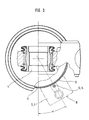
- Fig. 3 shows the suspension cylinder according to FIG. 2 in a view from above with partial breaks.
- the first articulation eye 4 is shown in section. Storage and seal are carried out in the usual way.
- the departure shows how the common housing 10 is arranged on the approach 12.
- the groove 14 encompasses the approach so that a clamping device, not shown, can effect the holder.
- the end face 13 of the housing is adapted to the radius of the outer wall of the protective tube 6.
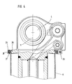
- Fig. 4 shows a broken section of the suspension cylinder in a section.
- the arrangement of the tensioning clamp 25 and the tensioning screw 26 can be seen, these encompassing an auxiliary ring, which can be designed as a retaining ring, in order to mount the protective tube 6 on the suspension cylinder.
- the protective tube 6 has, on its first conically widened region, first guide surfaces 28 which cooperate with second guide surfaces 29 provided on the suspension cylinder. This results in a positive connection in the cylinder longitudinal extension of the suspension cylinder and protective tube 6.
- the protective tube 6 is shown in detail in FIGS. 5 and 6.
- the extension 12 is designed as a guide strip, such that an essentially cylindrical profile 30 is connected to the protective tube 6 by means of a web 31.
- the cylindrical profile 30 is a preferred embodiment, but other profile shapes matched to the groove 14 are also conceivable.
- the markings 15 are located on both sides of the common housing and are arranged in such a way that the arrowheads of the markings 15 can reach very close to the outer wall of the protective tube.
- the common housing 10 according to FIG. 7 is shown in a front view in FIG. 8.
- the groove 14 arranged in the end face 13 of the common housing 10 is essentially cylindrical to encompass the extension 12.
- the clamping device 16 is designed such that the cross section of the groove 14 is reduced by tightening the screw with nut 33.
- a slot is provided adjacent to the groove 14.
- Fig. 8 also shows a connection 34 for a connecting cable.
- FIG. 9 shows the common housing 10 according to FIG. 7 in a top view.
- the sensors 2 and 3 are arranged offset in the circumferential direction and also have a switching distance 35. This switching distance is predetermined by the arrangement of the sensors 2 and 3 in the common housing 10, but can be changed as desired in a further embodiment of the invention.
Landscapes
- Engineering & Computer Science (AREA)
- General Engineering & Computer Science (AREA)
- Mechanical Engineering (AREA)
- Vehicle Body Suspensions (AREA)
Applications Claiming Priority (2)
| Application Number | Priority Date | Filing Date | Title |
|---|---|---|---|
| DE4112549 | 1991-04-17 | ||
| DE4112549 | 1991-04-17 |
Publications (3)
| Publication Number | Publication Date |
|---|---|
| EP0509191A2 true EP0509191A2 (fr) | 1992-10-21 |
| EP0509191A3 EP0509191A3 (en) | 1992-12-09 |
| EP0509191B1 EP0509191B1 (fr) | 1997-05-21 |
Family
ID=6429797
Family Applications (1)
| Application Number | Title | Priority Date | Filing Date |
|---|---|---|---|
| EP92101091A Expired - Lifetime EP0509191B1 (fr) | 1991-04-17 | 1992-01-23 | Arrangement de détecteur pour cylindre de suspension d'un contrÔle d'assiette |
Country Status (4)
| Country | Link |
|---|---|
| EP (1) | EP0509191B1 (fr) |
| AT (1) | ATE153285T1 (fr) |
| DE (1) | DE59208510D1 (fr) |
| ES (1) | ES2101760T3 (fr) |
Family Cites Families (4)
| Publication number | Priority date | Publication date | Assignee | Title |
|---|---|---|---|---|
| US4054295A (en) * | 1976-08-16 | 1977-10-18 | General Motors Corporation | Vehicle body support and leveler device |
| US4141572A (en) * | 1977-07-18 | 1979-02-27 | Monroe Auto Equipment Company | Vehicle leveling strut |
| DE3512232A1 (de) * | 1985-02-07 | 1986-08-14 | Liebherr-Werk Ehingen Gmbh, 7930 Ehingen | Hydropneumatische achsfederung fuer fahrzeuge, vorzugsweise auto- und mobilkrane |
| EP0323020A3 (fr) * | 1987-12-28 | 1991-01-09 | Ford Motor Company Limited | Capteur de hauteur de suspension, actionné par force, pour véhicule automobile |
-
1992
- 1992-01-23 AT AT92101091T patent/ATE153285T1/de not_active IP Right Cessation
- 1992-01-23 DE DE59208510T patent/DE59208510D1/de not_active Expired - Fee Related
- 1992-01-23 ES ES92101091T patent/ES2101760T3/es not_active Expired - Lifetime
- 1992-01-23 EP EP92101091A patent/EP0509191B1/fr not_active Expired - Lifetime
Also Published As
| Publication number | Publication date |
|---|---|
| EP0509191A3 (en) | 1992-12-09 |
| DE59208510D1 (de) | 1997-06-26 |
| ATE153285T1 (de) | 1997-06-15 |
| EP0509191B1 (fr) | 1997-05-21 |
| ES2101760T3 (es) | 1997-07-16 |
Similar Documents
| Publication | Publication Date | Title |
|---|---|---|
| DE3344010C1 (de) | Halterung fuer Annaeherungsfuehler | |
| EP0285909A1 (fr) | Amortisseur de chocs | |
| EP0288736A2 (fr) | Amortisseur de chocs I | |
| EP0670427A1 (fr) | Unité d'avance à fluide | |
| DE19712829B4 (de) | Vorrichtung zur Erkennung der Position eines beweglichen Gegenstandes | |
| EP0207270B1 (fr) | Dispositif de commutation fonctionnant sans contact par détecteur de proximité | |
| DE102021207650A1 (de) | Schieberventil mit geringer Neigung zum hydraulischen Klemmen | |
| EP0630452B1 (fr) | Distributeur proportionnel | |
| EP1390959A2 (fr) | Ensemble magnetique | |
| EP0509191B1 (fr) | Arrangement de détecteur pour cylindre de suspension d'un contrÔle d'assiette | |
| DE4343879A1 (de) | Elektromagnet, insbesondere für ein hydraulisches Ventil | |
| EP1648626A1 (fr) | Dispositif de laminage | |
| DE3605388C2 (de) | Elektrohydraulische Schaltvorrichtung | |
| DE3546865C2 (de) | Kolben-Zylinder-Anordnung | |
| DE3524414C2 (de) | Linearantrieb | |
| DE202023106730U1 (de) | Positions-Messsystem für Stellventil am Flansch | |
| DE9116215U1 (de) | Fühlereinrichtung für Federungszylinder einer Niveauregulierung | |
| DE1027414B (de) | Pneumatisches Lehrenmessgeraet | |
| DE3532988C2 (de) | Elektrohydraulische Schaltvorrichtung | |
| DE8632990U1 (de) | Berührungsloser Sensor | |
| DE3502615A1 (de) | Anschlaganordnung fuer eine druckmittelbetaetigte kolben-zylinder-einheit | |
| DE3622925C2 (de) | Kombiniertes Umschalt- und Druckbegrenzungsventil | |
| EP4416393B1 (fr) | Dispositif d'actionnement électrohydraulique à éléments fonctionnels électriques intégrés | |
| EP1691165A1 (fr) | Dispositif destiné à la vérification des tolérances de dimension, de forme et de position d'une pièce mécanique | |
| DE9308261U1 (de) | Schalterbetätigungseinrichtung |
Legal Events
| Date | Code | Title | Description |
|---|---|---|---|
| PUAI | Public reference made under article 153(3) epc to a published international application that has entered the european phase |
Free format text: ORIGINAL CODE: 0009012 |
|
| PUAL | Search report despatched |
Free format text: ORIGINAL CODE: 0009013 |
|
| AK | Designated contracting states |
Kind code of ref document: A2 Designated state(s): AT BE CH DE DK ES FR GB GR IT LI LU NL SE |
|
| AK | Designated contracting states |
Kind code of ref document: A3 Designated state(s): AT BE CH DE DK ES FR GB GR IT LI LU NL SE |
|
| 17P | Request for examination filed |
Effective date: 19921119 |
|
| RBV | Designated contracting states (corrected) |
Designated state(s): AT BE DE ES FR GB IT NL SE |
|
| 17Q | First examination report despatched |
Effective date: 19951027 |
|
| GRAG | Despatch of communication of intention to grant |
Free format text: ORIGINAL CODE: EPIDOS AGRA |
|
| GRAH | Despatch of communication of intention to grant a patent |
Free format text: ORIGINAL CODE: EPIDOS IGRA |
|
| GRAH | Despatch of communication of intention to grant a patent |
Free format text: ORIGINAL CODE: EPIDOS IGRA |
|
| GRAA | (expected) grant |
Free format text: ORIGINAL CODE: 0009210 |
|
| AK | Designated contracting states |
Kind code of ref document: B1 Designated state(s): AT BE DE ES FR GB IT NL SE |
|
| REF | Corresponds to: |
Ref document number: 153285 Country of ref document: AT Date of ref document: 19970615 Kind code of ref document: T |
|
| REF | Corresponds to: |
Ref document number: 59208510 Country of ref document: DE Date of ref document: 19970626 |
|
| ET | Fr: translation filed | ||
| REG | Reference to a national code |
Ref country code: ES Ref legal event code: FG2A Ref document number: 2101760 Country of ref document: ES Kind code of ref document: T3 |
|
| GBT | Gb: translation of ep patent filed (gb section 77(6)(a)/1977) |
Effective date: 19970715 |
|
| PG25 | Lapsed in a contracting state [announced via postgrant information from national office to epo] |
Ref country code: AT Free format text: LAPSE BECAUSE OF NON-PAYMENT OF DUE FEES Effective date: 19980123 |
|
| PG25 | Lapsed in a contracting state [announced via postgrant information from national office to epo] |
Ref country code: SE Free format text: LAPSE BECAUSE OF NON-PAYMENT OF DUE FEES Effective date: 19980124 |
|
| PG25 | Lapsed in a contracting state [announced via postgrant information from national office to epo] |
Ref country code: BE Free format text: LAPSE BECAUSE OF NON-PAYMENT OF DUE FEES Effective date: 19980131 |
|
| PLBE | No opposition filed within time limit |
Free format text: ORIGINAL CODE: 0009261 |
|
| STAA | Information on the status of an ep patent application or granted ep patent |
Free format text: STATUS: NO OPPOSITION FILED WITHIN TIME LIMIT |
|
| 26N | No opposition filed | ||
| BERE | Be: lapsed |
Owner name: WEBER-HYDRAULIK G.M.B.H. Effective date: 19980131 |
|
| PG25 | Lapsed in a contracting state [announced via postgrant information from national office to epo] |
Ref country code: NL Free format text: LAPSE BECAUSE OF NON-PAYMENT OF DUE FEES Effective date: 19980801 |
|
| NLV4 | Nl: lapsed or anulled due to non-payment of the annual fee |
Effective date: 19980801 |
|
| EUG | Se: european patent has lapsed |
Ref document number: 92101091.4 |
|
| PGFP | Annual fee paid to national office [announced via postgrant information from national office to epo] |
Ref country code: ES Payment date: 20011227 Year of fee payment: 11 |
|
| REG | Reference to a national code |
Ref country code: GB Ref legal event code: IF02 |
|
| PG25 | Lapsed in a contracting state [announced via postgrant information from national office to epo] |
Ref country code: ES Free format text: LAPSE BECAUSE OF NON-PAYMENT OF DUE FEES Effective date: 20030124 |
|
| REG | Reference to a national code |
Ref country code: ES Ref legal event code: FD2A Effective date: 20030124 |
|
| PGFP | Annual fee paid to national office [announced via postgrant information from national office to epo] |
Ref country code: GB Payment date: 20050112 Year of fee payment: 14 |
|
| PG25 | Lapsed in a contracting state [announced via postgrant information from national office to epo] |
Ref country code: GB Free format text: LAPSE BECAUSE OF NON-PAYMENT OF DUE FEES Effective date: 20060123 |
|
| GBPC | Gb: european patent ceased through non-payment of renewal fee |
Effective date: 20060123 |
|
| PGFP | Annual fee paid to national office [announced via postgrant information from national office to epo] |
Ref country code: IT Payment date: 20080124 Year of fee payment: 17 |
|
| PGFP | Annual fee paid to national office [announced via postgrant information from national office to epo] |
Ref country code: FR Payment date: 20080118 Year of fee payment: 17 |
|
| PGFP | Annual fee paid to national office [announced via postgrant information from national office to epo] |
Ref country code: DE Payment date: 20090125 Year of fee payment: 18 |
|
| REG | Reference to a national code |
Ref country code: FR Ref legal event code: ST Effective date: 20091030 |
|
| PG25 | Lapsed in a contracting state [announced via postgrant information from national office to epo] |
Ref country code: FR Free format text: LAPSE BECAUSE OF NON-PAYMENT OF DUE FEES Effective date: 20090202 |
|
| PG25 | Lapsed in a contracting state [announced via postgrant information from national office to epo] |
Ref country code: DE Free format text: LAPSE BECAUSE OF NON-PAYMENT OF DUE FEES Effective date: 20100803 |
|
| PG25 | Lapsed in a contracting state [announced via postgrant information from national office to epo] |
Ref country code: IT Free format text: LAPSE BECAUSE OF NON-PAYMENT OF DUE FEES Effective date: 20090123 |