EP0509204B1 - Einrichtung zum Walzen von Stabstahl und Draht - Google Patents
Einrichtung zum Walzen von Stabstahl und Draht Download PDFInfo
- Publication number
- EP0509204B1 EP0509204B1 EP92102242A EP92102242A EP0509204B1 EP 0509204 B1 EP0509204 B1 EP 0509204B1 EP 92102242 A EP92102242 A EP 92102242A EP 92102242 A EP92102242 A EP 92102242A EP 0509204 B1 EP0509204 B1 EP 0509204B1
- Authority
- EP
- European Patent Office
- Prior art keywords
- roll
- fitting
- rolling
- rollers
- exit
- Prior art date
- Legal status (The legal status is an assumption and is not a legal conclusion. Google has not performed a legal analysis and makes no representation as to the accuracy of the status listed.)
- Expired - Lifetime
Links
- 238000005096 rolling process Methods 0.000 title claims abstract description 38
- 239000000463 material Substances 0.000 claims abstract description 5
- 230000007704 transition Effects 0.000 claims abstract description 4
- 229910000831 Steel Inorganic materials 0.000 claims description 4
- 239000010959 steel Substances 0.000 claims description 4
- XLYOFNOQVPJJNP-UHFFFAOYSA-N water Substances O XLYOFNOQVPJJNP-UHFFFAOYSA-N 0.000 claims description 4
- 238000001816 cooling Methods 0.000 claims description 3
- 239000000498 cooling water Substances 0.000 claims 1
- 230000009760 functional impairment Effects 0.000 description 1
- 238000000034 method Methods 0.000 description 1
Images

Classifications
-
- B—PERFORMING OPERATIONS; TRANSPORTING
- B21—MECHANICAL METAL-WORKING WITHOUT ESSENTIALLY REMOVING MATERIAL; PUNCHING METAL
- B21B—ROLLING OF METAL
- B21B39/00—Arrangements for moving, supporting, or positioning work, or controlling its movement, combined with or arranged in, or specially adapted for use in connection with, metal-rolling mills
- B21B39/14—Guiding, positioning or aligning work
- B21B39/16—Guiding, positioning or aligning work immediately before entering or after leaving the pass
- B21B39/165—Guides or guide rollers for rods, bars, rounds, tubes ; Aligning guides
-
- B—PERFORMING OPERATIONS; TRANSPORTING
- B21—MECHANICAL METAL-WORKING WITHOUT ESSENTIALLY REMOVING MATERIAL; PUNCHING METAL
- B21B—ROLLING OF METAL
- B21B1/00—Metal-rolling methods or mills for making semi-finished products of solid or profiled cross-section; Sequence of operations in milling trains; Layout of rolling-mill plant, e.g. grouping of stands; Succession of passes or of sectional pass alternations
- B21B1/16—Metal-rolling methods or mills for making semi-finished products of solid or profiled cross-section; Sequence of operations in milling trains; Layout of rolling-mill plant, e.g. grouping of stands; Succession of passes or of sectional pass alternations for rolling wire rods, bars, merchant bars, rounds wire or material of like small cross-section
- B21B1/18—Metal-rolling methods or mills for making semi-finished products of solid or profiled cross-section; Sequence of operations in milling trains; Layout of rolling-mill plant, e.g. grouping of stands; Succession of passes or of sectional pass alternations for rolling wire rods, bars, merchant bars, rounds wire or material of like small cross-section in a continuous process
Definitions
- Rolling in calibers is the most common form of rolling bars and wire. In the pre-season, the most common work is with box or spike edge calibers. Aligning the inlet fittings to the caliber is very complex. According to DE-A-32 24 022 a method is known in which worked wildly on smooth rollers only. The selected calibration can only be used if the b / h ratio is less than 1.5.
- the design of the inlet and outlet fittings, which must extend to the middle of the roll, collide in the middle of the roll and the contour of which is precisely adapted to the roll radius, is very complex. This means that it is not possible to roll different cross-sections with one and the same pair of rollers or fittings.
- the inlet fitting has fluted inner sides which are adapted to the width of the rolling stock and which are to be adjusted with a play of 1 to 5 mm to the rolling stock. Since different steel grades also have different widths, this setting is complicated and hardly feasible. The differentiated spread can exceed the range mentioned. So when changing the material, the valve must also be changed or its setting changed.
- the connected inlet and outlet fittings form a "tunnel", which is heated up so much that it leads to deformations and functional impairments and the scale clogs the guides, which leads to accidents.
- the invention specified in claims 1 to 4 is based on the problem, starting from the prior art mentioned at the outset, to develop a device which simplifies the setting of the rollers and fittings and limits the diagonal distortion of the rolling stock.
- the invention improves the guidance of the material, minimizes the number and time for the roll change and increases the availability of the rolling mill.
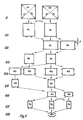
- FIG. 1 A suitable caliber sequence is shown in FIG. 1.
- Square cross-sections Oa) or rectangular cross-sections Ob) with the same area are used for piercing.
- the individual variants are illustrated using the example of eight roll passes.
- the first stitch is formed by a flat stitch 1a or, if the rolling diagonals d1 / d2 ⁇ 1.02 require it, by a box caliber 1b.
- d1 always represents the larger diagonal.
- the rolling stock in the stands G2, G3, G4, G5, G6, G7 passes through the flat stitches 2a, 3a, 4a, 5a, 6a, 7a, and then in the stand G8 into a Swedish oval 8s.
- the outlet cross-section from the last flat stitch is 900 mm2 ⁇ A ⁇ 15700 mm2 depending on the application cross-section.
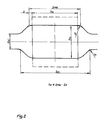
- the geometry for the Sweden oval 8s is shown in FIG. 2.
- caliber 2b, 4b, 6b and flaxed 3a, 5a, 7a alternate slightly from scaffold G2, whereupon the Swedish oval 8s again runs through as a transition to the shape calibers.
- a flat rolling sequence or the exchange of flat passes and slightly cut calibers can be guaranteed in advance.
- the use of one or two slightly incised calibres 6b, 7b in front of the Sweden oval 8s is only selected if the other preceding stands are rolled without a caliber.
- a further variant consists in that after stand G1, provided with uncalibrated rollers for flat stitch 1a or box caliber 1b, the flat stitches 2a and 3a follow.
- the G7 framework can also be provided with a slightly incised 7b caliber.
- An additional possibility is given if, after the flat stitches 1a and 2a, the slightly incised calibers 3b, 4b, followed by the flat stitches 5a, 6a, 7a or the slightly incised caliber 7b. It is also possible to design the slightly incised calibers 2b, 3b, 4b, 5b, 6b as a box caliber 1b and to design the transition to the shape caliber as a Swedish oval 8s. In reverse duos and trios, the scaffolds are identical to the sequence of stitches.
- the ratio of the rolling stock height h 1 to the double screwing depth 2 t is in the range 2 ⁇ h 1/2 t ⁇ 10.
- the geometrical relationships between the incoming rolling stock and the Swedish oval 8s can be seen in FIG. 2.
- the dimensioning is chosen so that the wear occurring in the caliber is minimized as far as possible and a trouble-free rolling process is guaranteed.
- the distance z is calculated from the caliber dimensions caliber basic width b KG , caliber depth b k , radius R, caliber height h K and roll gap s W , which indicates the distance from the intersection of the straight line of the caliber flank and caliber base - b KG - the radius R begins.
- the caliber must be dimensioned so that the incoming dimension of the rolling stock, the rolling stock height h o , the requirement h o ⁇ b KG - 2z and the inlet fitting is positioned so that the central inlet is guaranteed in any case, ie the rolling stock is not starts up in radius R, which would result in increased wear. From the description it can be seen that, regardless of the steel grades to be rolled, after the first rolling stand has been passed, the rolling stock passes through the subsequent rolling stands in n ⁇ 1 caliber-free passes, form passes in n ⁇ 1 cut or shape calibres and this is repeated as often as required.
- the inlet fitting 13 in the first roll stand for flat rolls is designed as a 4-roller fitting.
- a double roller valve (not shown in more detail) is arranged in the subsequent rolling stands. Seen in the rolling direction, the rolling stock is fed to the rollers 16, 16 'via an inlet funnel 6, an inlet-side pair of rollers 5, 5', a lateral guide surface with an integrated water box 2 and a pair of rollers-side rollers 4, 4 '.
- the setting of the roller pairs 5, 5 'and 4, 4' to the rolling stock is chosen so that b o ⁇ a ⁇ c, where b o incoming rolling stock dimension, a distance between the two rollers of the roller pair 4, 4 'to each other and c distance of the means two rollers of the pair of rollers 5, 5 'to each other.
- Slots 3 are provided in the water box 2 for cooling the pairs of rollers 5, 5 'and 4, 4'.
- the inlet fitting 13 is provided with guide jaws 1, 1 'which accommodate the wear plates 7, 7'.
- the outer contour 17 of the guide jaws 1, 1 ' is not necessarily adapted to the rolling geometry and is at a distance of 3 to 40 mm from the rollers 16, 16'. Behind the rollers 16, 16 ', the scraper 14 of the outlet fitting is arranged at a distance f from the center of the roller as a function of the roller gap s w , the same conditions as above.
- the outer contours 18 of the scraper 14 are at a distance of 3 to 5 mm from the roller surface.
- Characteristic of the dimensioning of the scraper 14 is that its height g between the top and bottom plate 9, 10 the tapered rolling height h 1 depending on the roll gap s w and the distance i of the cheeks 8, 8 'the tapering rolling stock width b 1 depending on the rolling gap s w towers.
- Openings 15 are provided in the stripper 14 between the upper, lower part and cheeks 8, 8 ′ in order to improve the cooling and to flush out the scale.
- slots 11 are arranged in the lower part through which scale and water can run off.
- the setting of the 4-roller valve is chosen so that the distance c of the inlet-side roller pair 5, 5 'is 0 to 5 mm greater than the distance a of the roller-side roller pair 4, 4', which in turn with the condition - 2 ⁇ s w ⁇ 3 mm for the incoming rolling stock dimension b.
- the roll angle of attack ⁇ is chosen for a continuous stack so that it satisfies the condition in the mill stand G1 14 ⁇ ⁇ ⁇ 30 ° and in the subsequent mill stands G2 to G7 18 ⁇ ⁇ ⁇ 40 °. For reversal duo and trio, 14 ⁇ ⁇ ⁇ 30 ° applies. These values refer to new rollers.
- the ratio b o / h o is ⁇ 2.3.
Landscapes
- Engineering & Computer Science (AREA)
- Mechanical Engineering (AREA)
- Metal Rolling (AREA)
Description
- Das Walzen in Kalibern ist die am meisten praktizierte Form beim Walzen von Stabstahl und Draht. Dabei wird in der Vorstaffel am häufigsten mit Kasten- bzw. Spießkantkalibern gearbeitet.
Sehr aufwendig ist das Ausrichten der Einlaufarmaturen zum Kaliber. Nach DE-A-32 24 022 ist ein Verfahren bekannt, bei dem ausschließlich auf Glattwalzen gearbeitet wild. Die gewählte Kalibrierung ist nur bei einem b/h-Verhältnis Kleiner 1,5 einsetzbar. Sehr aufwendig ist hierbei die Gestaltung der Ein- und Auslaufarmaturen, die bis Walzenmitte reichen müssen, in der Walzenmitte zusammenstoßen und in ihrer Kontur genau an den Walzenradius angepaßt sind. Damit ist das Walzen unterschiedlicher Querschnitte mit ein und demselben Walzenpaar bzw. Armatur nicht möglich. Außerdem wird gefordert, daß die Einlaufarmatur ausgekehlte Innenseiten aufweist, die der Breitung des Walzgutes angepaßt sind und die mit einem Spiel von 1 bis 5 mm zum Walzgut eingestellt werden sollen. Da unterschiedliche Stahlqualitäten auch unterschliedlich breiten, ist diese Einstellung kompliziert und kaum realisierbar. Die differenzierte Breitung kann den genannten Bereich überschreiten. So muß bei Materialwechsel die Armatur mit gewechselt werden bzw. ihre Einstellung verändert werden. Die in verbundener Form ausgebildeten Ein- und Auslaufarmaturen bilden einen "Tunnel", der so stark aufgeheizt wird, daß es zu Verformungen und Funktionsbeeinträchtigungen kommt und der Zunder die Führungen zusetzt, was zu Havarien führt. - Der in den Ansprüchen 1 bis 4 angegebenen Erfindung liegt das Problem zugrunde, ausgehend vom eingangs erwähnten Stand der Technik eine Einrichtung zu entwickeln, die die Einstellung der Walzen und Armaturen vereinfacht und den Diagonalverzug des Walzgutes begrenzt.
Durch die Erfindung wird die Führung des Materials verbessert, die Anzahl und die Zeit für den Walzenwechsel minimiert und die Verfügbarkeit der Walzstraße erhöht. - Die Erfindung soll nachstehend an einem Ausführungsbeispiel näher erläutert werden. Es zeigen:
- Fig. 1:
- geeignete Kaliberfolgen
- Fig. 2:
- geeignete Abmessungen vom 1. Formkaliber (Schwedenoval) zum einlaufenden Walzgut
- Fig. 3:
- die Einrichtung für das kaliberlose Walzen
- Fig. 4:
- einen Schnitt nach Fig. 3.
- In der Fig. 1 ist eine geeignete Kaliberfolge dargestellt. Zum Anstich kommen Quadratquerschnitt Oa) bzw. flächengleiche Reckteckquerschnitte Ob). Am Beispiel von acht Walzstichen werden die Einzelvarianten dargelegt. Der erste Stich wird von einem Flachstich 1a oder, wenn es die Walzgutdiagonalen d₁/d₂ ≧ 1,02 erfordern, von einem Kastenkaliber 1b gebildet. Hierbei stellt d₁ immer die zahlenmäßig größere Diagonale dar.
- In der ersten Variante durchläuft das Walzgut in den Gerüsten G2, G3, G4, G5, G6, G7 die Flachstiche 2a, 3a, 4a, 5a, 6a, 7a, um dann im Gerüst G8 in ein Schwedenoval 8s einzulaufen. Der Abgangsquerschnitt aus dem letzten Flachstich liegt in Abhängigkeit vom Einsatzquerschnitt bei 900 mm² ≦ A ≦ 15700 mm². Die Geometrie für das Schwedenoval 8s wird in der Fig. 2 dargestellt. In einer zweiten Variante folgen ab Gerüst G2 abwechselnd leicht eingeschnittene Kaliber 2b, 4b, 6b und Flachsliche 3a, 5a, 7a, worauf sich wieder das Schwedenoval 8s als Übergang zu den Formkalibern durchläuft. Weiterhin besteht die Möglichkeit, vor Beginn der Formkaliberfolge ein Formkaliber 7b oder zwei leicht eingeschnittene Kaliber 6b anzuordnen, um im Bedarfsfall (nach Anzahl der Flachstiche oder Materialgeschwindigkeit) die Verschleißgefahr zu senken. Dabei kann vorab eine Flachwalzfolge oder das Wechseln von Flachstichen und leicht eingeschnittenen Kalibern gewährleistet werden. Vorzugsweise wird der Einsatz von einem oder zwei leicht eingeschnittenen Kalibern 6b, 7b vor dem Schwedenoval 8s nur dann gewählt, wenn in den übrigen vorangesetzten Gerüsten kaliberlos gewalzt wird. Eine weitere Variante besteht darin, daß nach Gerüst G1, versehen mit unkalibrierten Walzen für den Flachstich 1a oder Kastenkaliber 1b, die Flachstiche 2a und 3a folgen. Danach schließen sich die leicht eingeschnittenen Kaliber 4b und 5b an, auf die wiederum die Flachstiche 6a und 7a folgen. Das Gerüst G7 kann dabei auch mit einem leicht eingeschnittenen Kaliber 7b versehen werden. Eine zusätzliche Möglichkeit ist gegeben, wenn nach den Flachstichen 1a und 2a die leicht eingeschnittenen Kaliber 3b, 4b, darauf die Flachstiche 5a, 6a, 7a bzw. das leicht eingeschnittene Kaliber 7b folgen. Es ist auch möglich, die leicht eingeschnittenen Kaliber 2b, 3b, 4b, 5b, 6b als Kastenkaliber 1b auszuführen und den Übergang in das Formkaliber als Schwedenoval 8s auszugestalten. Bei Umkehrduos und Trios sind die Gerüste identisch mit den Stichfolgen. Charakteristisch ist, daß bei leicht eingeschnittenen Kalibern das Verhältnis von auslaufender Walzguthöhe h₁ zur doppelten Eindrehtiefe 2t im Bereich 2 ≦ h₁/2t ≦ 10 liegt. Die geometrischen Verhältnisse vom einlaufenden Walzgut und dem Schwedenoval 8s sind in der Fig. 2 ersichtlich. Die Bemessung ist so gewählt, daß der im Kaliber auftretende Verschleiß maximal minimiert wird und ein störungsfreier Walzvorgang gewährleistet ist. Aus den Kaliberabmessungen Kalibergrundbreite bKG, Kalibertiefe bk, Radius R, Kaliberhöhe hK und Walzspalt sW wird der Abstand z errechnet, der angibt, in welcher Entfernung zum Schnittpunkt der Geraden von Kaliberflanke und Kalibergrund - bKG - der Radius R beginnt. Das Kaliber muß so bemessen sein, daß die einlaufende Abmessung des Walzgutes, die Walzguthöhe ho, der Forderung ho ≦ bKG - 2z genügt und die Einlaufarmatur so positioniert wird, daß auf jeden Fall der mittige Einlauf gewährleistet ist, d. h. das Walzgut nicht im Radius R anläuft, was erhöhten Verschleiß zur Folge hätte. Aus der Beschreibung ist ersichtlich, daß, unabhängig von den zu walzenden Stahlqualitäten, das Walzgut nach Durchlauf des 1. Walzgerüstes die nachfolgenden Walzgerüste in n ≧ 1 kaliberlosen Stichen durchläuft, Formstiche in n ≧ 1 angeschnittenen oder Formkalibern anschließen und dies beliebig oft wiederholt wird.
- Gem. Fig. 3 und 4 ist erfindungsgemäß die Einlaufarmatur 13 im 1. Walzgerüst bei Flachwalzen als 4-Rollenarmatur ausgeführt. In den nachfolgenden Walzgerüsten sind statt der 4-Rollenarmatur je eine Doppelrollenarmatur (nicht näher dargestellt) angeordnet. In Walzrichtung gesehen, wird das Walzgut über Einlauftrichter 6, einlaufseitigem Rollenpaar 5, 5', seitlicher Führungsfläche mit integriertem Wasserkasten 2 und walzenseitigem Rollenpaar 4, 4', den Walzen 16, 16' zugeführt. Die Einstellung der Rollenpaare 5, 5' und 4, 4' zum Walzgut wird so gewählt, daß bo ≦ a ≦ c ist, wobei bo einlaufende Walzgutabmessung, a Abstand der beiden Walzen des Rollenpaares 4, 4' zueinander und c Abstand der beiden Walzen des Rollenpaares 5, 5' zueinander bedeutet. In dem Wasserkasten 2 sind Schlitze 3 zum Kühlen der Rollenpaare 5, 5' und 4, 4' vorgesehen. Gerüstseitig ist die Einlaufarmatur 13 mit Führungsbacken 1, 1' versehen, die die Verschleißplatten 7, 7' aufnehmen. Die Führungsbacken 1, 1' enden in Abhängigkeit vom Walzspalt sw mit einem Abstand f vor Walzenmitte, wobei gilt:


Die Verschleißplatten 7, 7' weisen einen Abstand d auf wobei d > b₁ gilt, b₁ ist die auslaufende Walzgutbreite. Die Führungsbacken 1, 1' verhindern mit den Verschleißbacken 7, 7' ein Kippen bzw. Verdrehen des Walzgutes. Die Außenkontur 17 der Führungsbacken 1, 1' ist nicht zwingend an die Walzgeometrie angepaßt und weist einen Abstand von 3 bis 40 mm zu den Walzen 16, 16' auf.
Hinter den Walzen 16, 16' ist der Abstreifer 14 der Auslaufarmatur in Abhängigkeit vom Walzspalt sw im Abstand f zur Walzenmitte angeordnet, wobei die gleichen Verhältnisse wie o. g. gelten. Die Außenkonturen 18 des Abstreifers 14 weisen einen Abstand von 3 bis 5 mm zur Walzenoberfläche auf. Charakteristisch für die Bemessung des Abstreifers 14 ist, daß sein Höhenmaß g zwischen Ober- und Unterplatte 9, 10 die auslaufende Walzguthöhe h₁ in Abhängigkeit vom Walzspalt sw und der Abstand i der Wangen 8, 8' die auslaufende Walzgutbreite b₁ in Abhängigkeit vom Walzspalt sw überragt. Dabei gilt:


Die Einlaufarmatur 13 weist zwischen ihrem Unterteil und dem Seitenteil Öffnungen 12 auf, durch die der Zunder herausgespült wird. Im Abstreifer 14 sind zwischen Ober-, Unterteil und Wangen 8, 8' Öffnungen 15 vorhanden, um die Kühlung zu verbessern und den Zunder herauszuspülen. Zusätzlich sind Schlitze 11 im Unterteil angeordnet, über die Zunder und Wasser ablaufen kann. Die Einstellung der 4-Rollenarmatur ist so gewählt, daß der Abstand c des einlaufseitigen Rollenpaares 5, 5' um 0 bis 5 mm größer ist als der Abstand a des walzseitigen Rollenpaares 4, 4', der wiederum mit der Bedingung - 2 ≦ sw ≦ 3 mm zur einlaufenden Walzgutabmessung b eingestellt ist. Der Walzenangriffswinkel α wird für eine Kontistaffel so gewählt, daß er im Walzgerüst G1 der Kaliberfolge der Bedingung genügt 14 ≦ α ≦ 30° und in den nachfolgenden Walzgerüsten G2 bis G7 18 ≦ α ≦ 40°. Bei Umkehrduo und Trio gilt 14 ≦ α ≦ 30°. Diese Werte beziehen sich auf neue Walzen. Das Verhältnis bo/ho ist ≦ 2,3.
Claims (4)
- Einrichtung zum Walzen von Stabstahl und Draht in Kontistaffeln, Umkehrduos und Trios auf unkalibrierten Walzen, unabhängig von den zu walzenden Stahlqualitäten, bestehend aus in Walzrichtung nacheinander angeordneter Einlaufarmatur, den Walzen und einer Auslaufarmatur, dadurch gekennzeichnet, daß im ersten Walzgerüst beim Flachwalzen einlaufseitig eine 4-Rollenarmatur und in den nachfolgenden Walzgerüsten jeweils eine Doppelrollenarmatur angeordnet ist, und sowohl 4-Rollenarmatur als auch Doppelrollenarmatur jeweils mit einer Armaturkühlung in Form seitlich angeordneter Wasserkästen (2, 2') versehen ist, die in Richtung der Rollenpaare (4, 4' und 5, 5') zum Ableiten von Zunder und Kühlwasser Schlitze (3) und am Übergang zu einem Unterteil Öffnungen (12) aufweisen und in Führungsbacken (1, 1') Verschleißplatten (7, 7') angeordnet sind, auslaufseitig ein Abstreifer (14) vorgesehen ist, der aus einer Unter- und Oberplatte (10, 9) mit dazwischen angeordneten Wangen (8, 8') besteht und zwischen Unter- und Oberplatte (10, 9) sowie Wangen (8, 9) Öffnungen (15) und in der Unterplatte (10) Schlitze (11) vorgesehen sind.
- Einrichtung nach Anspruch 1, dadurch gekennzeichnet, daß in Abhängigkeit vom Walzspalt sw der Walzen (16, 16') folgende Bedingungen gelten:
für Ein- und Auslaufarmatur zur Walzenmitte f


für Auslaufarmatur als Abstand zur auslaufenden Walzguthöhe h


für Auslaufarmatur als Abstand zur auslaufenden Walzspaltbreite b


- Einrichtung nach Anspruch 1, dadurch gekennzeichnet, daß die Einstellmaße der 4-Rollenarmatur so gewählt sind, daß am einlaufseitigen Rollenpaar (5, 5') ein von 0 bis 5 mm größeres Spiel gewählt ist als am walzseitigen Rollenpaar (4, 4'), wobei letzteres wiederum mit einem Spiel eingestellt ist, das den Bedingungen - 2 ≦ sw ≦ 3 mm genügt.
- Einrichtung nach einem der Ansprüche 1 bis 3, dadurch gekennzeichnet, daß die Walzen (16, 16') der Walzgerüste einer Kontistaffel so eingestellt sind, daß im 1. Walzgerüst der Greifwinkel 14 ≦ α ≦ 30° und bei den nachfolgenden Walzgerüsten 18 ≦ α ≦ 40° bei neuen Walzen nicht überschreitet und ein bo/ho-Verhältnis von ≦ 2,3 besteht, wobei der Anstichvorgang im 1. Walzgerüst unterstützt wird.
Applications Claiming Priority (2)
| Application Number | Priority Date | Filing Date | Title |
|---|---|---|---|
| DE4112931 | 1991-04-18 | ||
| DE4112931A DE4112931A1 (de) | 1991-04-18 | 1991-04-18 | Verfahren und einrichtung zum walzen von stabstahl und draht |
Publications (3)
| Publication Number | Publication Date |
|---|---|
| EP0509204A2 EP0509204A2 (de) | 1992-10-21 |
| EP0509204A3 EP0509204A3 (en) | 1992-12-16 |
| EP0509204B1 true EP0509204B1 (de) | 1995-04-19 |
Family
ID=6429991
Family Applications (1)
| Application Number | Title | Priority Date | Filing Date |
|---|---|---|---|
| EP92102242A Expired - Lifetime EP0509204B1 (de) | 1991-04-18 | 1992-02-11 | Einrichtung zum Walzen von Stabstahl und Draht |
Country Status (6)
| Country | Link |
|---|---|
| EP (1) | EP0509204B1 (de) |
| AT (1) | ATE121322T1 (de) |
| CS (1) | CS119192A3 (de) |
| DE (2) | DE4112931A1 (de) |
| RU (1) | RU2105619C1 (de) |
| SK (1) | SK279259B6 (de) |
Families Citing this family (9)
| Publication number | Priority date | Publication date | Assignee | Title |
|---|---|---|---|---|
| RU2221654C1 (ru) * | 2002-06-05 | 2004-01-20 | Магнитогорский государственный технический университет им. Г.И.Носова | Способ изготовления низкоуглеродистой арматурной проволоки |
| RU2349402C1 (ru) * | 2007-06-22 | 2009-03-20 | Открытое акционерное общество "Электростальский завод тяжелого машиностроения" | Задний стол трубопрокатного стана |
| RU2354473C1 (ru) * | 2007-07-16 | 2009-05-10 | Открытое акционерное общество "Магнитогорский металлургический комбинат" | Устройство для натяжения движущейся полосы |
| DE102010009593A1 (de) * | 2010-02-26 | 2011-09-01 | Kocks Technik Gmbh & Co. Kg | Walzgerüst |
| RU2680336C1 (ru) * | 2016-12-12 | 2019-02-19 | федеральное государственное автономное образовательное учреждение высшего образования "Южно-Уральский государственный университет (национальный исследовательский университет)" | Непрерывный мелкосортный стан с разделяющей раскат системой калибров |
| CN108405638B (zh) * | 2018-03-14 | 2021-02-26 | 马鞍山钢铁股份有限公司 | 一种线材轧件导槽及防止线材轧件划伤的方法 |
| CN111644461A (zh) * | 2020-05-25 | 2020-09-11 | 山东莱钢永锋钢铁有限公司 | 一种轧制设备的轧制方法 |
| CN112575450A (zh) * | 2020-12-09 | 2021-03-30 | 申洲针织(安徽)有限公司 | 一种自动缝制锁眼 |
| CN117619909B (zh) * | 2024-01-25 | 2024-04-02 | 江苏盛日机械设备制造有限公司 | 一种角钢轧制导卫 |
Family Cites Families (4)
| Publication number | Priority date | Publication date | Assignee | Title |
|---|---|---|---|---|
| US3600924A (en) * | 1969-03-28 | 1971-08-24 | Denzil O Martin | Method of rolling titanium and other rods |
| AU458531B2 (en) * | 1973-08-06 | 1975-02-27 | M.I.M. Rolling Consultants (Aust.) Pty. Ltd. | Rod rolling |
| SE399521B (sv) * | 1974-09-24 | 1978-02-20 | Metalform Ab | Sett att i ett flertal stick nedvalsa ett metallemne |
| GB2101025B (en) * | 1981-06-30 | 1985-10-02 | Kawasaki Steel Co | Rolling steel rods and wires with grooveless rolls |
-
1991
- 1991-04-18 DE DE4112931A patent/DE4112931A1/de not_active Withdrawn
-
1992
- 1992-02-11 AT AT92102242T patent/ATE121322T1/de not_active IP Right Cessation
- 1992-02-11 EP EP92102242A patent/EP0509204B1/de not_active Expired - Lifetime
- 1992-02-11 DE DE59201943T patent/DE59201943D1/de not_active Expired - Fee Related
- 1992-04-17 CS CS921191A patent/CS119192A3/cs unknown
- 1992-04-17 RU SU5011342A patent/RU2105619C1/ru active
- 1992-04-17 SK SK1191-92A patent/SK279259B6/sk unknown
Also Published As
| Publication number | Publication date |
|---|---|
| ATE121322T1 (de) | 1995-05-15 |
| EP0509204A3 (en) | 1992-12-16 |
| EP0509204A2 (de) | 1992-10-21 |
| DE4112931A1 (de) | 1992-10-22 |
| RU2105619C1 (ru) | 1998-02-27 |
| DE59201943D1 (de) | 1995-05-24 |
| SK279259B6 (sk) | 1998-08-05 |
| CS119192A3 (en) | 1992-11-18 |
Similar Documents
| Publication | Publication Date | Title |
|---|---|---|
| EP0230644A1 (de) | Anordung zum Entfernen von Zunder von warmgewalzten Stahlbänden | |
| EP0509204B1 (de) | Einrichtung zum Walzen von Stabstahl und Draht | |
| DE3127190C2 (de) | ||
| DE60001999T2 (de) | Längsteilvorrichtung zur Herstellung von mehreren Profilen | |
| DE69204545T2 (de) | Verfahren zur Herstellung von Profilen und/oder Stäben im kalten Zustand. | |
| DE2741962C2 (de) | Walzstraße zum Walzen von Draht oder stabförmigem Gut | |
| EP2464473A1 (de) | Verfahren zum vieladrigen entgraten von drahtadern und zugehörige vorrichtung | |
| DE69128432T2 (de) | Verfahren und vorrichtung zur herstellung von metallstäben | |
| DE69209632T2 (de) | Verfahren und Vorrichtung zum Walzen von Metallen zur Herstellung von rundem Stabmaterial oder Walzdraht aus rundem Stab- oder Drahtmaterial mit grösserem Durchmesser | |
| DE69004558T2 (de) | Vorrichtung zum Walzen und Längsteilen ohne Verwindung und Verfahren zur Herstellung von Bewehrungsstäben. | |
| DE19506224C2 (de) | Walzenrichtmaschine zum Richten von Blechen | |
| DE3417500A1 (de) | Duo-reversier-walzgeruest, insbesondere zum walzen von profilstahlquerschnitten | |
| DE102010011608A1 (de) | Richtwalze, Richtwalzenanordnung und Zwei-Walzen-Richtmaschine | |
| DE1814950C3 (de) | Universalgerüst zum Herstellen von asymmetrischen, H-förmigen Stahlprofilen | |
| DE538630C (de) | Fuehrungseinrichtung fuer die einzelnen Staender von kontinuierlichen Blech- und Streifenwalzwerken | |
| DE69300944T2 (de) | Verfahren und Vorrichtung zum Herstellen von einzelnen runden Stangen im warmen Zustand aus warmen Mehrfachelementen. | |
| DE2659318A1 (de) | Verfahren zum walzen von rundstahl | |
| DE2524224A1 (de) | Verfahren und vorrichtung zum walzen von stabstahl | |
| EP0845310A1 (de) | Drahtkühlung | |
| DE69513263T2 (de) | Vorrichtung zum Stranggiessen von Produkten mit einem Rundprofilabschnitt und Produkten mit einem Profilabschnitt mit ebener Fläche | |
| EP0870554B1 (de) | Walzenstrasse zum Walzen von Flachstahl | |
| EP4257259A1 (de) | Rollgang einer walzanlage mit verbesserten seitenführungsrollen | |
| DE2458087A1 (de) | Einadriges walzwerk mit ortsfester walzmitte | |
| DE10200441B4 (de) | Walzenstraße zum Walzen von Draht oder Feineisen | |
| DE258507C (de) |
Legal Events
| Date | Code | Title | Description |
|---|---|---|---|
| PUAI | Public reference made under article 153(3) epc to a published international application that has entered the european phase |
Free format text: ORIGINAL CODE: 0009012 |
|
| AK | Designated contracting states |
Kind code of ref document: A2 Designated state(s): AT CH DE FR GB IT LI SE |
|
| PUAL | Search report despatched |
Free format text: ORIGINAL CODE: 0009013 |
|
| AK | Designated contracting states |
Kind code of ref document: A3 Designated state(s): AT CH DE FR GB IT LI SE |
|
| 17P | Request for examination filed |
Effective date: 19930602 |
|
| 17Q | First examination report despatched |
Effective date: 19931119 |
|
| GRAA | (expected) grant |
Free format text: ORIGINAL CODE: 0009210 |
|
| AK | Designated contracting states |
Kind code of ref document: B1 Designated state(s): AT CH DE FR GB IT LI SE |
|
| REF | Corresponds to: |
Ref document number: 121322 Country of ref document: AT Date of ref document: 19950515 Kind code of ref document: T |
|
| GBT | Gb: translation of ep patent filed (gb section 77(6)(a)/1977) |
Effective date: 19950419 |
|
| ET | Fr: translation filed | ||
| REF | Corresponds to: |
Ref document number: 59201943 Country of ref document: DE Date of ref document: 19950524 |
|
| ITF | It: translation for a ep patent filed | ||
| PLBE | No opposition filed within time limit |
Free format text: ORIGINAL CODE: 0009261 |
|
| STAA | Information on the status of an ep patent application or granted ep patent |
Free format text: STATUS: NO OPPOSITION FILED WITHIN TIME LIMIT |
|
| PG25 | Lapsed in a contracting state [announced via postgrant information from national office to epo] |
Ref country code: LI Effective date: 19960229 Ref country code: CH Effective date: 19960229 |
|
| 26N | No opposition filed | ||
| REG | Reference to a national code |
Ref country code: CH Ref legal event code: PL |
|
| PGFP | Annual fee paid to national office [announced via postgrant information from national office to epo] |
Ref country code: SE Payment date: 19980121 Year of fee payment: 7 |
|
| PGFP | Annual fee paid to national office [announced via postgrant information from national office to epo] |
Ref country code: FR Payment date: 19980127 Year of fee payment: 7 |
|
| PGFP | Annual fee paid to national office [announced via postgrant information from national office to epo] |
Ref country code: DE Payment date: 19980128 Year of fee payment: 7 Ref country code: AT Payment date: 19980128 Year of fee payment: 7 |
|
| PGFP | Annual fee paid to national office [announced via postgrant information from national office to epo] |
Ref country code: GB Payment date: 19980210 Year of fee payment: 7 |
|
| REG | Reference to a national code |
Ref country code: FR Ref legal event code: TP |
|
| REG | Reference to a national code |
Ref country code: GB Ref legal event code: 732E |
|
| PG25 | Lapsed in a contracting state [announced via postgrant information from national office to epo] |
Ref country code: GB Free format text: LAPSE BECAUSE OF NON-PAYMENT OF DUE FEES Effective date: 19990211 Ref country code: AT Free format text: LAPSE BECAUSE OF NON-PAYMENT OF DUE FEES Effective date: 19990211 |
|
| PG25 | Lapsed in a contracting state [announced via postgrant information from national office to epo] |
Ref country code: SE Free format text: LAPSE BECAUSE OF NON-PAYMENT OF DUE FEES Effective date: 19990212 |
|
| GBPC | Gb: european patent ceased through non-payment of renewal fee |
Effective date: 19990211 |
|
| PG25 | Lapsed in a contracting state [announced via postgrant information from national office to epo] |
Ref country code: FR Free format text: LAPSE BECAUSE OF NON-PAYMENT OF DUE FEES Effective date: 19991029 |
|
| EUG | Se: european patent has lapsed |
Ref document number: 92102242.2 |
|
| PG25 | Lapsed in a contracting state [announced via postgrant information from national office to epo] |
Ref country code: DE Free format text: LAPSE BECAUSE OF NON-PAYMENT OF DUE FEES Effective date: 19991201 |
|
| REG | Reference to a national code |
Ref country code: FR Ref legal event code: ST |
|
| PG25 | Lapsed in a contracting state [announced via postgrant information from national office to epo] |
Ref country code: IT Free format text: LAPSE BECAUSE OF NON-PAYMENT OF DUE FEES;WARNING: LAPSES OF ITALIAN PATENTS WITH EFFECTIVE DATE BEFORE 2007 MAY HAVE OCCURRED AT ANY TIME BEFORE 2007. THE CORRECT EFFECTIVE DATE MAY BE DIFFERENT FROM THE ONE RECORDED. Effective date: 20050211 |