EP0509220A2 - Conteneur prismatique à claire-voie avec un revêtement - Google Patents
Conteneur prismatique à claire-voie avec un revêtement Download PDFInfo
- Publication number
- EP0509220A2 EP0509220A2 EP92103627A EP92103627A EP0509220A2 EP 0509220 A2 EP0509220 A2 EP 0509220A2 EP 92103627 A EP92103627 A EP 92103627A EP 92103627 A EP92103627 A EP 92103627A EP 0509220 A2 EP0509220 A2 EP 0509220A2
- Authority
- EP
- European Patent Office
- Prior art keywords
- container
- walls
- box
- side walls
- lattice
- Prior art date
- Legal status (The legal status is an assumption and is not a legal conclusion. Google has not performed a legal analysis and makes no representation as to the accuracy of the status listed.)
- Withdrawn
Links
Images

Classifications
-
- B—PERFORMING OPERATIONS; TRANSPORTING
- B65—CONVEYING; PACKING; STORING; HANDLING THIN OR FILAMENTARY MATERIAL
- B65D—CONTAINERS FOR STORAGE OR TRANSPORT OF ARTICLES OR MATERIALS, e.g. BAGS, BARRELS, BOTTLES, BOXES, CANS, CARTONS, CRATES, DRUMS, JARS, TANKS, HOPPERS, FORWARDING CONTAINERS; ACCESSORIES, CLOSURES, OR FITTINGS THEREFOR; PACKAGING ELEMENTS; PACKAGES
- B65D25/00—Details of other kinds or types of rigid or semi-rigid containers
- B65D25/14—Linings or internal coatings
- B65D25/16—Loose, or loosely-attached, linings
Definitions
- the invention relates to a lining for prismatic lattice boxes, which consist of bottom, end and side walls and have a frame-like border connected to the end and side walls, which delimits a rectangular access opening, the clear dimensions of which are smaller than those between the lattice boxes.
- Lattice boxes in particular lattice box exchange pallets, are used for the storage and transport of various goods.
- a film bag is used as the lining.
- this accepts the disadvantage that, in the case of bulk goods and in particular in the case of granules, the plastic film of the film bags swells out through the mesh. The film bag can easily be injured at these swelling points.
- it would be conceivable to place supporting walls in the lattice box against which the film bag is placed but this proposal would also be incomplete because the film bag can be injured when it is inserted and leakage losses occur after the material has been filled.
- the object of the invention is to provide a novel lining for lattice boxes with the disadvantages mentioned be avoided.
- the novel lining should be reusable and insensitive to mechanical stress and allow a liquid-tight design at least in its lower third.
- the lining consists of a container made of plastic, which is intended for use as a removable insert used in the grid box, the outer dimensions in the bottom area are smaller than the top edge and at most correspond approximately to the inner dimensions of the access opening of the grid box , while the outer dimensions of the upper edge are approximately the same as the inside dimensions of the mesh box, that the container is at least semi-flexible in its upper half so that the four corner areas of the upper edge of the container lie within the vertically projected bottom contour due to the inward curvature of the front and side walls thus fit through the access opening of the lattice box and that the walls of the container are designed to be resilient, so that after removal of the forces causing the inward curvature of the container walls, the container walls for contacting the lattice box walls outward into their A Snap back exit levels.
- Such an insert container for lattice boxes must both fulfill the condition that it can be easily inserted into and removed from the lattice box and secondly must ensure that the container is held securely in the grid box.
- a prismatic rigid container cannot meet these conditions because of the border provided on the upper edge.
- the container according to the invention fulfills both conditions.
- Both embodiments of the container according to the invention ensure absolute tightness, so that problematic liquids can also be transported. Pointed objects can also be filled in as bulk goods, which would be impermissible in the prior art.
- the insert container according to the invention does not necessarily have to have a height equal to the inside height of the lattice box, an advantageous embodiment is, however, that the upper edge of the container is at least close to the edge border, which generally consists of an angle iron frame exists.
- a container is particularly advantageous which, apart from its rounded edges, is formed from an upside-down regular truncated pyramid with end and side walls diverging upwards. Such containers can be nested to save space.
- one longitudinal wall of the container has a lower height than the other longitudinal wall, at least in its central region.
- the container therefore has a side access opening, which is advantageous if a plurality of lattice boxes are stacked one above the other. Since these lattice boxes also have a flap in at least one longitudinal wall and the longitudinal wall of the container has a lateral access opening corresponding to the flap height, access from the side is also possible at all times.
- two containers can be put into one another - rotated relatively through 180 ° - so that this container combination can also be filled up to the top of the container, if the side access is unnecessary.
- a further embodiment of the invention consists in that a circumferentially closed support frame is assigned to the container that closely surrounds it in its lower area and whose outer dimensions correspond to those of the upper edge of the container.
- the support frame is rigid.
- the height of the support frame is chosen so that it can be inserted canted through the upper access opening of the mesh box.
- the support frame is then supported on the outside of the lattice box and on the inside offers a contact surface for the container, so that even pourable or flowable media of high density can be filled into the container without imposing an impermissible load on it.
- the support frame can also be designed to be flexible, so that the height restriction is eliminated.
- the support frame is preferably designed with a molded-on base as a leak-proof shell.
- the floor can be thin-walled and an additional safety moment against leakage is created.
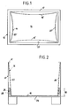
- the lattice box generally designated 10, has two side walls and two end walls which are perpendicular to a floor. At the upper edge of the container walls there is a frame-like border 12 which is formed from an angle iron frame.
- a plastic container 14 has a flat bottom 16 and flat side walls 18 and also flat end walls 20.
- the surround 12 of the lattice box 10 delimits a rectangular access opening 22 and the bottom 16 of the container 14 is dimensioned such that it just fits into the access opening 22.
- the two side walls 18 and the two end walls 20 of the container 14 diverge upwards. The angle that each container wall forms with the vertical is the same.
- the divergence angle is determined by the outer dimensions of the container 14 at the level of its upper edge, because in this upper edge plane the outer dimensions of the container 14 correspond at least approximately to the corresponding inner dimensions of the lattice box 10.
- its side and end walls 18, 20 In order to insert the container 14 into the lattice box 10, its side and end walls 18, 20 must be arched inwards into the positions 18 'and 20', respectively the container is shortened in length and width. After the bottom 16 of the container 14 is placed on the bottom of the lattice box 10, the side and end walls are released so that they snap back into their flat positions by themselves and lie against the corresponding walls of the lattice box 10. The container 14 is removed accordingly.
- the container 14 is made of polyethylene.
- the wall thickness is small. Nevertheless, it offers the possibility of absorbing liquids, pasty masses and bulk goods as well as heavy general cargo.
- a support frame 24 is used between the walls of the lattice box 10 and the walls 18, 20 of the container 14, which in the exemplary embodiment is designed with a base 26, so that the support frame and base form a trough.
- the support frame 24 is designed as a hollow body which is provided with a padding 28 made of hard foam or the like.
- the outer and inner walls of the support frame 24 could also be stiffened by horizontal ribs. It is essential that the support frame 24 permits support of the container walls 18, 20 all around and is preferably supported on the outside of the walls of the lattice box 10.
- the support frame 24 thus forms a spacer ring, which is the distance between the container 14 and the mesh box 10 in the lower part of the combination 10, 14. Thanks to this support frame 24, the container 14 is positioned immovably in the mesh box 10. Even when the combination is in an inclined position, this position is retained, which might not be the case because of the deformable side walls of the container 14. In addition, the support frame 24 allows the thin-walled container 14 to be loaded with bulk or flowing goods of high density. The container wall is relieved of pressure in the lower area at risk, since this is absorbed by the support frame 24 which, if properly dimensioned, in turn supports itself on the lattice box 10.
- the height 30 of the support frame 24 is selected so that it fits without deformation with appropriate tilting through the access opening 22 of the lattice box 10 delimited by the border 12. Since the support frame 24 should nestle on the inside and outside of the container walls 18, 20 or the lattice box walls, the wall thickness of the support frame 24 tapers upwards in accordance with the taper of the container 14, the outer surfaces of the support frame 24 being arranged vertically, that is to say stand at right angles on the floor 26.
- FIG. 3 illustrates the same mesh box 10 as FIGS. 1 and 2, but the container 15 differs from the container 14 in that it is highly flexible and preferably also elastically deformable and that it is a prismatic container in which the container walls are at least approximately vertical on the floor. A certain conicity can only be desirable for space-saving nesting.
- the outer dimensions of the bottom of the container 15 are at least approximately equal to the corresponding inner dimensions of the lattice box 10, and since the container walls of the container 15 are essentially vertical, the outer cross section of the container 15 is approximately equal to the inner cross section of the lattice box 10 at any height.
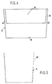
- FIGS. 4 and 5 illustrate a container 14 which differs from the previously described embodiment in that that a side wall 18 in the central region does not extend to the upper edge of the container 14, but ends approximately at half height, so that a lateral access opening 32 is formed, which, however, does not extend over the entire width of the longitudinal wall 18, rather at short distances from the end walls 20 ends, so that longitudinal wall webs 34 remain which laterally limit the access opening 32.
- These longitudinal wall webs 34 increase the rigidity of the container 14.
- the access opening 32 makes it possible to access the contents of a lattice box even when several such lattice boxes are stacked one on top of the other, because the lattice boxes have flaps in the longitudinal wall, after which the contents of the container are opened by the lateral access opening 32 is accessible.
Landscapes
- Engineering & Computer Science (AREA)
- Mechanical Engineering (AREA)
- Stackable Containers (AREA)
- Packages (AREA)
Applications Claiming Priority (2)
| Application Number | Priority Date | Filing Date | Title |
|---|---|---|---|
| DE19914108387 DE4108387A1 (de) | 1991-03-15 | 1991-03-15 | Auskleidung fuer prismatische gitterboxen |
| DE4108387 | 1991-03-15 |
Publications (2)
| Publication Number | Publication Date |
|---|---|
| EP0509220A2 true EP0509220A2 (fr) | 1992-10-21 |
| EP0509220A3 EP0509220A3 (en) | 1993-02-10 |
Family
ID=6427345
Family Applications (1)
| Application Number | Title | Priority Date | Filing Date |
|---|---|---|---|
| EP19920103627 Withdrawn EP0509220A3 (en) | 1991-03-15 | 1992-03-03 | Lining for prismatic skeleton containers |
Country Status (2)
| Country | Link |
|---|---|
| EP (1) | EP0509220A3 (fr) |
| DE (1) | DE4108387A1 (fr) |
Cited By (2)
| Publication number | Priority date | Publication date | Assignee | Title |
|---|---|---|---|---|
| AU726038B2 (en) * | 1995-06-21 | 2000-10-26 | B A Lancaster Limited | Containers and bins |
| CN106945948A (zh) * | 2017-04-28 | 2017-07-14 | 中国电建集团贵阳勘测设计研究院有限公司 | 一种粗碎车间卸料仓防撞击方法及装置 |
Family Cites Families (10)
| Publication number | Priority date | Publication date | Assignee | Title |
|---|---|---|---|---|
| US2297097A (en) * | 1940-08-31 | 1942-09-29 | Wilson F Best | Receptacle |
| AT218949B (de) * | 1960-08-05 | 1961-12-27 | Ernst Robathin | Tragkorb |
| DE1173014B (de) * | 1961-08-16 | 1964-06-25 | Volkswagenwerk Ag | Stapelbarer Fluessigkeits-Einsatzbehaelter, insbesondere fuer den Transport von Lackfarbe |
| AT247782B (de) * | 1963-12-14 | 1966-06-27 | Huels Chemische Werke Ag | Gitterboxpalette |
| CH548330A (de) * | 1972-02-18 | 1974-04-30 | Thurnherr Albert | Behaelter fuer kehrichtsaecke. |
| FR2472514A1 (fr) * | 1979-12-31 | 1981-07-03 | Sotralentz Sa | Conteneur sur palette avec dispositif de protection en treillis plie |
| EP0109191A3 (fr) * | 1982-10-14 | 1984-12-12 | Robert Feiron Shambrook | Empilage de sacs de matières en vrac |
| EP0220922A3 (fr) * | 1985-10-25 | 1988-08-03 | Dietmar J. Neumann | Conteneur flexible |
| DE3724764C1 (en) * | 1987-07-25 | 1988-09-15 | Lorraine De Recuperation De Re | Appliance for transporting liquid metallurgical slag |
| DE8801027U1 (de) * | 1988-01-28 | 1988-03-17 | Edelhoff Polytechnik Gmbh & Co, 58640 Iserlohn | Sammelbehälter |
-
1991
- 1991-03-15 DE DE19914108387 patent/DE4108387A1/de not_active Withdrawn
-
1992
- 1992-03-03 EP EP19920103627 patent/EP0509220A3/de not_active Withdrawn
Cited By (2)
| Publication number | Priority date | Publication date | Assignee | Title |
|---|---|---|---|---|
| AU726038B2 (en) * | 1995-06-21 | 2000-10-26 | B A Lancaster Limited | Containers and bins |
| CN106945948A (zh) * | 2017-04-28 | 2017-07-14 | 中国电建集团贵阳勘测设计研究院有限公司 | 一种粗碎车间卸料仓防撞击方法及装置 |
Also Published As
| Publication number | Publication date |
|---|---|
| EP0509220A3 (en) | 1993-02-10 |
| DE4108387A1 (de) | 1992-09-17 |
Similar Documents
| Publication | Publication Date | Title |
|---|---|---|
| DE3819911C2 (fr) | ||
| DE4117159C2 (de) | Transport- und/oder Lagerbehälter | |
| DE2449952C3 (de) | Zellenschachtel für Eier | |
| DE68910647T2 (de) | Versandbehälter zum Verpacken von Artikeln. | |
| DE1586869B1 (de) | Einstueckig geformter Karton zur Aufnahme empfindlicher Gegenstaende,insbesondere Eier | |
| DE69308661T2 (de) | Stapelbare-Ineinandersetzbare Verpackungskiste mit Seiten nach Skelett-Bauart | |
| DE3101975A1 (de) | Verpackung fuer eine vielzahl von ausstellungspackungen | |
| DE1586889B1 (de) | Verschliessbarer Kunststoffbehaelter zum Verpacken von Nahrungsmitteln | |
| DE8209245U1 (de) | Zusammenlehbarer Container | |
| DE2729737B2 (de) | Dicht verschließbarer, unterteilbarer Behälter | |
| DE19641686C2 (de) | Stapelbarer Behälter, insbesondere Lager- und Transportbehälter sowie Behältersystem | |
| EP0509220A2 (fr) | Conteneur prismatique à claire-voie avec un revêtement | |
| EP0440844B1 (fr) | Caisses avec des moyens pour relier les unes aux autres des caisses par liaison momentanée | |
| DE4317300C2 (de) | Kastenförmiger Behälter aus Kunststoff | |
| DE1960113C3 (de) | Kasten aus Kunststoff | |
| DE2200945A1 (de) | Stapel- und verschachtelbarer Behaelter | |
| DE3319802A1 (de) | Horde zur aufnahme von gegenstaenden | |
| DE4224217C2 (de) | Behälter | |
| DE202013100968U1 (de) | Palettenbox | |
| DE202018104281U1 (de) | Container | |
| DE202018102107U1 (de) | Stapelbehälter und Transportsystem für derartige Behälter | |
| DE9316073U1 (de) | Behälter zum Drehstapeln | |
| CH421804A (de) | Stapelbarer Kunststoffbehälter, insbesondere Flaschenkasten | |
| DE3843853C2 (de) | Dose | |
| DE20017500U1 (de) | Faltkarton mit einer Palette |
Legal Events
| Date | Code | Title | Description |
|---|---|---|---|
| PUAI | Public reference made under article 153(3) epc to a published international application that has entered the european phase |
Free format text: ORIGINAL CODE: 0009012 |
|
| AK | Designated contracting states |
Kind code of ref document: A2 Designated state(s): AT BE CH DE DK ES FR GB GR IT LI LU NL PT SE |
|
| PUAL | Search report despatched |
Free format text: ORIGINAL CODE: 0009013 |
|
| AK | Designated contracting states |
Kind code of ref document: A3 Designated state(s): AT BE CH DE DK ES FR GB GR IT LI LU NL PT SE |
|
| 17P | Request for examination filed |
Effective date: 19930426 |
|
| 17Q | First examination report despatched |
Effective date: 19940328 |
|
| STAA | Information on the status of an ep patent application or granted ep patent |
Free format text: STATUS: THE APPLICATION IS DEEMED TO BE WITHDRAWN |
|
| 18D | Application deemed to be withdrawn |
Effective date: 19940730 |