EP0509264A2 - Machine de moulage - Google Patents
Machine de moulage Download PDFInfo
- Publication number
- EP0509264A2 EP0509264A2 EP92104814A EP92104814A EP0509264A2 EP 0509264 A2 EP0509264 A2 EP 0509264A2 EP 92104814 A EP92104814 A EP 92104814A EP 92104814 A EP92104814 A EP 92104814A EP 0509264 A2 EP0509264 A2 EP 0509264A2
- Authority
- EP
- European Patent Office
- Prior art keywords
- screw
- temperature
- flight
- melt
- resin
- Prior art date
- Legal status (The legal status is an assumption and is not a legal conclusion. Google has not performed a legal analysis and makes no representation as to the accuracy of the status listed.)
- Withdrawn
Links
- 238000000465 moulding Methods 0.000 title claims abstract description 33
- 239000000155 melt Substances 0.000 claims abstract description 61
- 229920005989 resin Polymers 0.000 claims abstract description 47
- 239000011347 resin Substances 0.000 claims abstract description 47
- 230000004888 barrier function Effects 0.000 claims abstract description 32
- 239000007787 solid Substances 0.000 claims abstract description 12
- 238000009826 distribution Methods 0.000 description 38
- 238000010438 heat treatment Methods 0.000 description 19
- 239000007924 injection Substances 0.000 description 13
- 230000006835 compression Effects 0.000 description 12
- 238000007906 compression Methods 0.000 description 12
- 238000002347 injection Methods 0.000 description 12
- 238000012360 testing method Methods 0.000 description 10
- 230000009467 reduction Effects 0.000 description 9
- 238000001746 injection moulding Methods 0.000 description 8
- 238000002156 mixing Methods 0.000 description 7
- 238000000034 method Methods 0.000 description 6
- 238000012546 transfer Methods 0.000 description 6
- 238000013461 design Methods 0.000 description 5
- 238000011156 evaluation Methods 0.000 description 5
- 238000010102 injection blow moulding Methods 0.000 description 4
- 238000005259 measurement Methods 0.000 description 4
- 230000007423 decrease Effects 0.000 description 3
- 230000008030 elimination Effects 0.000 description 3
- 238000003379 elimination reaction Methods 0.000 description 3
- 229920001903 high density polyethylene Polymers 0.000 description 3
- 239000004700 high-density polyethylene Substances 0.000 description 3
- 230000002159 abnormal effect Effects 0.000 description 2
- 230000008859 change Effects 0.000 description 2
- 230000001419 dependent effect Effects 0.000 description 2
- 230000000694 effects Effects 0.000 description 2
- 238000001125 extrusion Methods 0.000 description 2
- 230000020169 heat generation Effects 0.000 description 2
- 238000011160 research Methods 0.000 description 2
- 238000005979 thermal decomposition reaction Methods 0.000 description 2
- 229920005992 thermoplastic resin Polymers 0.000 description 2
- 230000015572 biosynthetic process Effects 0.000 description 1
- 238000000071 blow moulding Methods 0.000 description 1
- 238000011161 development Methods 0.000 description 1
- 239000007789 gas Substances 0.000 description 1
- 238000000227 grinding Methods 0.000 description 1
- 238000004519 manufacturing process Methods 0.000 description 1
- 239000000203 mixture Substances 0.000 description 1
- 238000010606 normalization Methods 0.000 description 1
- 239000008188 pellet Substances 0.000 description 1
- 238000010094 polymer processing Methods 0.000 description 1
- 230000002265 prevention Effects 0.000 description 1
- 230000008569 process Effects 0.000 description 1
- 238000004904 shortening Methods 0.000 description 1
- 230000009897 systematic effect Effects 0.000 description 1
Images






Classifications
-
- B—PERFORMING OPERATIONS; TRANSPORTING
- B29—WORKING OF PLASTICS; WORKING OF SUBSTANCES IN A PLASTIC STATE IN GENERAL
- B29C—SHAPING OR JOINING OF PLASTICS; SHAPING OF MATERIAL IN A PLASTIC STATE, NOT OTHERWISE PROVIDED FOR; AFTER-TREATMENT OF THE SHAPED PRODUCTS, e.g. REPAIRING
- B29C45/00—Injection moulding, i.e. forcing the required volume of moulding material through a nozzle into a closed mould; Apparatus therefor
- B29C45/17—Component parts, details or accessories; Auxiliary operations
- B29C45/46—Means for plasticising or homogenising the moulding material or forcing it into the mould
- B29C45/58—Details
- B29C45/60—Screws
Definitions
- This invention relates to a molding machine with a screw intermittently and/or periodically rotatable to plasticate a thermoplastic resin as in injection molding, blow molding or the like, and especially to the shape and dimensions of the screw.
- thermoplastic resin there are certain requirements for molding machines in which a screw is intermittently and/or periodically rotated to plasticate a thermoplastic resin as in injection molding, blow molding or the like.
- the temperature of the resin so plasticated should conform to the temperature setting of a heating cylinder and, moreover, should not vary within a shot (inter-shot) or from shot to shot (intrashot). In other words, a constant in temperature is required.
- inter-shot and intershot uniformity in composition is required. This is governed almost entirely by the mixing performance of the screw.
- the current situation is that, in a molding process where a screw is rotated in a noncontinuous manner, no screw has been designed and manufactured to the full satisfaction of users' demands and, as a matter of fact, neither users nor molding machine manufacturers have accurately ascertained the true nature of the problem.
- the present inventor developed a novel method for measuring the temperature of a molten resin within a shot in a dynamic state of injection by using a thermocouple arranged in a nozzle of the molding machine [Journal of Japan Polymer Processing Society: Seikei Kako ,1(4), "Measurement of Temperature and Pressure of Resin under Molding" (1989)].
- thermocouple It is known that the temperature of the flowing melt as determined by a sensor such as a thermocouple is considerably different from the temperature of the same resin as measured in a stationary state under atmospheric pressure. Similarly to gases, it is therefore essential to compare each resin temperature after converting it to a corresponding resin temperature in a standard state where the molten resin is maintained in a stationary state under atmospheric temperature.
- a molten resin is standardized into the standard state where the molten resin is in a stationary state under atmospheric pressure, so that corrected temperature and temperature distribution of the molten resin can be obtained. This has made it possible for the first time to conduct an accurate comparison in performance between various screws on the basis of the levels in temperature uniformity of molten resins plasticated by the screws.
- screws employed in injection or blow molding machines are full flight screws (Screw No. 10) which are constructed of a feed section 3, a compression section 2 and a metering section 1 as illustrated in FIG. 13.
- FIG. 14 shows the effects of the rate of screw rotation on temperature distribution curves obtained with Screw No.10 in the dynamic steady-state of injection.
- the temperature distribution curve can be obtained by normalization of the temperature profile to the standard temperature profile which is that of the first shot of injection as well as uniform in temperature of the melt stored in the reservoir of the heating barrel.
- the dimentions of various parts of Screw No.10 are tabulated in FIG. 7.
- High-density polyethylene (HDPE) is employed as the resin.
- the present invention has as a primary object the provision of a molding machine capable of providing a high plasticating rate while maintaining a narrow melt temperature distribution.
- the present invention provides a molding machine with a screw intermittently and/or periodically rotatable to plasticate a resin.
- the screw is a barrier flight screw having a main flight and an auxiliary flight.
- the main flight and auxiliary flight define a melt channel and a solid channel, and the melt channel has a depth at least 50% of the depth of the solid channel in a feed section.
- the length of an axial range of the barrier flight screw, in which the auxiliary flight is provided is at least 7 times the diameter of the barrier flight screw.
- the auxiliary flight has a height at least 0.3 mm but less than 1 mm lower than the main flight.
- the main flight preferably, has a pitch at least 0.9 times the diameter of the barrier flight screw.
- the present invention it is possible to narrow the temperature distribution of a melt within a shot in the dynamic steady-state of injection without lowering the plasticating rate of the resin and also to reduce variations in resin temperature between shots, thereby making it possible to achieve higher quality and accuracy while retaining the productivity of molded articles.
- the high temperature zone at the first half of the screw stroke is believed to be attributable to a temperature increase caused by the generation of heat due to shear forces applied as a result of rotation of the screw when transferring the melt from the metering section of the screw to the reservoir of the heating cylinder in the immediately- preceding molding cycle.
- the low temperature zone at the last half of the screw stroke appears to occur because a resin - whose temperature has not arisen sufficiently due to its insufficient preheating as a result of the stay in a low temperature zone of the heating cylinder, this zone extending from the compression section to the feed section of the screw, in the immediately preceding molding cycle - cannot be heated upto the temperature setting of the heating cylinder although the temperature of the resin has risen during passing through the metering section of the screw.
- An auxiliary flight in the present invention with a view toward eliminating the low temperature zone.
- An auxiliary flight is effective in preventing transfer of non-molten resin lumps (breakup of the solid-bed) from the solid channel to the melt channel of the screw used as well as heating up of the melt passing through the dam clearance between the tip of the barrier flight and the inner surface of the heating barrel.
- the ratio of the depth of the melt channel in the metering section to the depth of the solid channel which is the depth of the feed channel of the screw without the auxiliary flight (hereinafter called the "barrier flight")(Hm/Hf) at 0.5 or greater in this invention.
- the melt channel deeper as mentioned above, the generation of heat due to shear forces generated by rotation of the screw - said heat generation being the cause for the occurrence of the high temperature zone - can be reduced, thereby making it possible to eliminate the high temperature zone.
- the object of the present invention can basically be achieved.
- the length of an axial range of the screw, in which the barrier flight is provided at 7 times or more the diameter of the screw; to make the height of the barrier flight at least 0.3 mm but less than 1 mm lower than the main flight; and further to set the pitch of the main flight at least 0.9 times the diameter of the screw.
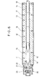
- the test was conducted by an injection molding machine ("UN-50", trade name; manufactured by Niigata Engineering Co., Ltd.) modified partly, which was shown in FIG. 6.
- the screws of the various shapes therein as illustrated in FIG. 6 were installed to this machine.
- a heating cylinder 10 of the injection molding machine was provided with thermocouples 15,16, .... which were adapted to measure temperatures in a front section 11, middle section 12, rear (front) section 13 and rear (rear) section 14 of the heating cylinder 10.
- a nozzle 20 was provided with a thermocouple 21 for measuring the temperature of the nozzle 20 itself and also with another thermocouple 22 for measuring the temperature of the melt injected from the reservoir 19.
- the nozzle 20 is also provided with a capillary die 25 which defined a capillary of 1 mm in diameter and 20 mm in length to make the flow path resistance constant during injection.
- Injection conditions were set as shown in FIG. 8.
- the temperature setting of the front section 11 of the heating cylinder 10 was chosen at 230 C.
- high-density polyethylene of the injection molding grade (“STAFLENE E880", trade name; product of Nippon Petrochemicals Co., Ltd.) was used.
- the molding machine Upon measurement, the molding machine was left for 30 minutes after the temperatures of the heating cylinder had reached their corresponding temperature settings, whereby the temperature of the melt inside a reservoir 19 of the heating cylinder 20 was made equal and uniform to the temperature of the front section 11 of the heating cylinder 10.
- Screw No. 1 a general full flight screw, was tested first.
- the basic shape of Screw No. 1 is, as shown in FIG. 2, similar to that of Screw No. 10 described above as a conventional screw.
- the dimensions of respective parts are set as shown in FIG. 7, in which the dimensions of the corresponding parts of various screws are also shown so that they may be compared to one another.
- Screw No. 1 has a similar basic shape to Screw No. 10, a similar tendency is observed in the temperature distribution when Screw No. 1 is used. As is depicted in FIG. 10, a high temperature zone appears in the first half of the screw stroke and a low temperature zone shows up in the last half of the screw stroke within a shot in the dynamic steady-state of injection. Further, the temperature difference between the high temperature zone and the low temperature zone becomes greater as the rotation speed of the screw increases.
- Screw No. 2 It is Screw No. 2 that was produced on a trial basis with a view toward eliminating the low temperature zone observed with Screw No. 1.
- the compression ratio CR was changed to 2.5 by setting the depth Hf of the feed channel at 3.75 mm.
- the low temperature zone in the last half of the screw stroke was indeed eliminated at the investigated screw rotation speed range of 100-300 rpm as shown in FIG. 10.
- the resin temperature in the high temperature zone in the first half of the screw stroke became still higher and at the same time, the charge time required to feed the resin in an amount corresponding to the stroke of 95 mm became longer, thereby leading to a reduction in the plasticating rate.
- a barrier flight It is the addition of a barrier flight that seems to be another effective method for the elimination of the low temperature zone.
- the principal function of a barrier flight is to prevent lumps of non-molten resin from transferring from the solid channel to the melt channel.
- the barrier flight is also known to be very useful for the prevention of the mixing of breakup of the solid-bed during extrusion. Therefore, in Screw No. 4 and Screw No. 5, a barrier flight 0.4 mm lower than the main flight was introduced to AH to the compression sections of Screw No. 1 and Screw No. 2 respectively, as illustrated in FIG. 3. Similarly to Screw No. 2 and Screw No. 3, these screws are both effective for the elimination of the low temperature zone. It has, however, been found that, as the screw rotation speed is increased, the resin temperature rises further over the entire range of the screw stroke and the plasticating rate is lowered significantly compared to Screw No. 1 and Screw No. 2 as shown in FIG. 9.
- the barrier flight would probably prevent the movement of the resin in the compression section, thus generating substantial heat under shear forces inside the resin.
- a second cause for the temperature increase there are probably the generation of heat by viscous flow as a result of flow of the melt through the metering section of the screw and also the generation of heat under shear forces as a result of rotation of the screw. Since the generation of heat by viscous flow is governed by the shear rate determined by dimensions of a flow path. It is possible to change the width and length of the flow path by grinding off the flight of the screw. As a result, the increase of the melt temperature may be probably restricted. Turning to the generation of heat under shear forces caused by rotation of the screw, it is expected to reduce the temperature increase of the melt by shortening the charge time.
- Screw No. 6 was fabricated on a trial basis to determine whether the temperature increase is predominantly governed by the heat generation caused by viscous flow or by the shear forces as a result of rotation of the screw.
- Screw No. 6 is, as shown in FIG. 4, similar to Screw No. 5 except for the elimination of the flight over about half the length of the metering section, and Screw No. 7 had the remaining half ground off.
- no substantial change was observed in the temperature distribution curve for each screw.
- a strong correlation was observed between the duration of the charge time and the increase of the melt temperature in the second shot with respect to each screw.
- Screw No. 1 which is a general full flight screw
- substantial improvements are observed in the average standard deviation of the melt temperature and the amplitude of the temperature distribution as depicted in FIG. 9.
- the average melt temperature (232.5 C) is higher than the temperature setting (230 C) of the heating cylinder and the plasticating rate is slow.
- Screw No. 81 therefore had the barrier flight of Screw No. 8 ground off over 0.2 mm to lower its height, namely, the dam clearance AH of Screw No. 8 was expanded to 0.6 mm to permit easy passage of the melt beyond the barrier flight in an attempt to increase the plasticating rate.
- the barrier flight of Screw No. 8 was ground off over 0.4 mm to lower its height, namely, the dam clearance AH of Screw No. 8 was expanded to 0.8 mm to ascertain influence of the height of the barrier flight.
- the dam clearance AH which is the difference in height between the main flight and the barrier flight, at a suitable dimension. This is desired because a narrow dam clearance AH obstructs the flow of the melt and so reduces the plasticating rate while an excessively wide dam clearance like Screw No. 82 permits the mixing of breakup of the solid-bed from the solid channel into the melt channel and results in an increased likelihood of the occurrence of an abnormal low melt temperature zone in the last half of the screw stroke.
- the suitable dimensional range of the dam clearance has been found to be at least 0.3 mm but less than 1 mm because of the dimension of the pellets of the resin.
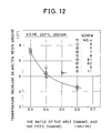
- melt channel it is indispensable to make the melt channel deeper than 50% of the depth of the solid channel in the feed section. It has been ascertained from the relationship between the charge time and the temperature increase of the second shot at the same rotation speed that the melt temperature of the high temperature zone in the first half of the screw stroke is caused by the generation of heat under shear forces as a result of rotation of the screw. The melt channel has, therefore, been deepened to reduce the generation of heat in the melt under shear forces.
- the melt temperature increase remains when the ratio of the depth of the melt channel to the depth of the solid channel in the feed section (Hm/Hf) becomes 0.5 and greater or when Hf/Hm becomes 2 and smaller. It is, therefore, possible to bring about the effects of a deepened melt channel when the channel depth ratio is set at 0.5 or greater.
- the channel depth ratio is preferably not greater than 1.0 from the view point of the production of the screw.
- Screw No. 9 is a barrier flight screw.
- the dam clearance AH is 0.4 mm.
- Screw No. 9 designed in such a shape and dimensions as described above, is superior to Screw No. 10, a conventional screw, in every evaluation item as shown in FIG. 9 and FIG. 10.
- Screw No. 9 has achieved an increase in the plasticating rate and a reduction in the amplitude of the temperature distribution of the melt.
- Screw No. 9 has also realized a reduction in the average standard deviation, which is an index for variations between shots, to a quarter or less of the average standard deviation of Screw No. 10.
- Screw No. 11 has been designed to have a mixing section whose length is 2D. Although any shape of mixing head can be attached to the mixing section, Screw No. 11 is in the form of a simple rod having the same diameter as the melt channel of the screw. Specific dimensions of the screw are given in FIG. 7.
- Screw No. 11 is also superior to Screw No. 10, a conventional screw, in every evaluation item as shown in FIG. 9 and FIG. 10. Screw No. 11 has achieved an increase in the plasticating rate and a reduction in the amplitude of the temperature distribution.
- Screw No. 11 is slightly faster in the plasticating rate and is lower in the average resin temperature, reflecting the increase in the volume of the channel of the screw owing to the reduction of the width W of the main flight and the width Wb of the barrier flight.
Landscapes
- Engineering & Computer Science (AREA)
- Manufacturing & Machinery (AREA)
- Mechanical Engineering (AREA)
- Injection Moulding Of Plastics Or The Like (AREA)
- Blow-Moulding Or Thermoforming Of Plastics Or The Like (AREA)
Applications Claiming Priority (2)
| Application Number | Priority Date | Filing Date | Title |
|---|---|---|---|
| JP83941/91 | 1991-04-16 | ||
| JP8394191A JPH05261781A (ja) | 1991-04-16 | 1991-04-16 | 成形機 |
Publications (2)
| Publication Number | Publication Date |
|---|---|
| EP0509264A2 true EP0509264A2 (fr) | 1992-10-21 |
| EP0509264A3 EP0509264A3 (en) | 1993-01-13 |
Family
ID=13816615
Family Applications (1)
| Application Number | Title | Priority Date | Filing Date |
|---|---|---|---|
| EP19920104814 Withdrawn EP0509264A3 (en) | 1991-04-16 | 1992-03-19 | Molding machine |
Country Status (3)
| Country | Link |
|---|---|
| EP (1) | EP0509264A3 (fr) |
| JP (1) | JPH05261781A (fr) |
| CA (1) | CA2064329A1 (fr) |
Cited By (4)
| Publication number | Priority date | Publication date | Assignee | Title |
|---|---|---|---|---|
| EP2236266A4 (fr) * | 2007-12-27 | 2011-09-07 | Sumitomo Heavy Industries | Injecteur |
| EP3278950A4 (fr) * | 2015-03-25 | 2018-12-12 | Sumitomo Heavy Industries, Ltd. | Dispositif d'injection, et vis |
| EP3275617A4 (fr) * | 2015-03-25 | 2018-12-12 | Sumitomo Heavy Industries, Ltd. | Dispositif d'injection, et vis |
| CN115697666A (zh) * | 2020-06-05 | 2023-02-03 | 发那科株式会社 | 注射成型机的控制装置和程序 |
Families Citing this family (2)
| Publication number | Priority date | Publication date | Assignee | Title |
|---|---|---|---|---|
| JP4721454B2 (ja) * | 2007-02-22 | 2011-07-13 | 日精樹脂工業株式会社 | 射出成形装置における成形条件の決定方法及び射出成形装置 |
| JP5142390B2 (ja) * | 2008-09-19 | 2013-02-13 | 株式会社名機製作所 | 可塑化装置および可塑化方法 |
Family Cites Families (3)
| Publication number | Priority date | Publication date | Assignee | Title |
|---|---|---|---|---|
| US4363768A (en) * | 1977-04-15 | 1982-12-14 | Hpm Corporation | Method of injection molding employing multichannel wave screw |
| US4752136A (en) * | 1986-07-23 | 1988-06-21 | Spirex Corporation | Extruder injection apparatus and method |
| JPS63291632A (ja) * | 1987-05-25 | 1988-11-29 | Mitsubishi Heavy Ind Ltd | 可塑化スクリュ |
-
1991
- 1991-04-16 JP JP8394191A patent/JPH05261781A/ja active Pending
-
1992
- 1992-03-19 EP EP19920104814 patent/EP0509264A3/en not_active Withdrawn
- 1992-03-27 CA CA 2064329 patent/CA2064329A1/fr not_active Abandoned
Cited By (5)
| Publication number | Priority date | Publication date | Assignee | Title |
|---|---|---|---|---|
| EP2236266A4 (fr) * | 2007-12-27 | 2011-09-07 | Sumitomo Heavy Industries | Injecteur |
| EP3278950A4 (fr) * | 2015-03-25 | 2018-12-12 | Sumitomo Heavy Industries, Ltd. | Dispositif d'injection, et vis |
| EP3275617A4 (fr) * | 2015-03-25 | 2018-12-12 | Sumitomo Heavy Industries, Ltd. | Dispositif d'injection, et vis |
| CN115697666A (zh) * | 2020-06-05 | 2023-02-03 | 发那科株式会社 | 注射成型机的控制装置和程序 |
| CN115697666B (zh) * | 2020-06-05 | 2025-11-28 | 发那科株式会社 | 注射成型机的控制装置和程序 |
Also Published As
| Publication number | Publication date |
|---|---|
| CA2064329A1 (fr) | 1992-10-17 |
| JPH05261781A (ja) | 1993-10-12 |
| EP0509264A3 (en) | 1993-01-13 |
Similar Documents
| Publication | Publication Date | Title |
|---|---|---|
| Chen et al. | Quality indexes design for online monitoring polymer injection molding | |
| Chen et al. | Monitoring, prediction and control of injection molding quality based on tie-bar elongation | |
| EP1439046B1 (fr) | Technique de moulage automatisé pour le moulage par injection de matières thermoplastiques | |
| EP0409982B1 (fr) | Unite de commande pour machines de moulage a injection | |
| USRE40952E1 (en) | Method and apparatus for measuring the temperature of molten material in a mold cavity | |
| Chen et al. | Optimization of clamping force for low-viscosity polymer injection molding | |
| Donovan et al. | An experimental study of plasticating in a reciprocating‐screw injection molding machine | |
| US6517754B1 (en) | Method for evaluating injection moulded parts | |
| CA2064329A1 (fr) | Machine a mouler | |
| Lindt | Pressure development in the melting zone of a single‐screw extruder | |
| Chen et al. | Quality monitoring and control for plasticization of acrylonitrile‐butadiene‐styrene regrind polymer in injection molding | |
| Amano et al. | Temperature measurements of polymer melts in the heating barrel during injection molding. Part 3: Effects of screw geometry | |
| Nishizawa | Heat controls and rubber flow behaviour in screw of extruder and injection machine and the problems occurring in these processes | |
| Frizelle | Injection molding technology | |
| Jaroschek | Injection molding for practitioners | |
| JPH0655600A (ja) | 加熱筒シリンダ−とノズルの温度を測定することによりスクリュ−を具備した成形機における樹脂の可塑化状態を制御する方法 | |
| Dininger | Three critical measurements on injection molding processes | |
| Jin et al. | An experimental study of solid‐bed break‐up in plasticization of a reciprocating‐screw injection molding | |
| EP1009611A1 (fr) | Entree en treillis pour le moulage par injection de melanges de caoutchouc | |
| JP7750019B2 (ja) | 射出成形方法および射出成形装置 | |
| Alqosaibi et al. | Advanced melt rheology control: a filling defects investigation for hot runner based injection molding | |
| Huang et al. | Quality Monitoring Methodology for Micro-Shrinkage of Thick-Walled Injection Molded Components | |
| US5957576A (en) | Screw for in-line screw type thermosetting resin injection molding machine | |
| Sudit | A study of heat-transfer characteristics of copper-alloy materials for use in injection molding | |
| Mitrovic | Criterion Determination of Completely Worn Out Elements of Tribomechanical System on Extruders |
Legal Events
| Date | Code | Title | Description |
|---|---|---|---|
| PUAI | Public reference made under article 153(3) epc to a published international application that has entered the european phase |
Free format text: ORIGINAL CODE: 0009012 |
|
| AK | Designated contracting states |
Kind code of ref document: A2 Designated state(s): DE FR GB IT |
|
| PUAL | Search report despatched |
Free format text: ORIGINAL CODE: 0009013 |
|
| AK | Designated contracting states |
Kind code of ref document: A3 Designated state(s): DE FR GB IT |
|
| 17P | Request for examination filed |
Effective date: 19930621 |
|
| 17Q | First examination report despatched |
Effective date: 19950302 |
|
| STAA | Information on the status of an ep patent application or granted ep patent |
Free format text: STATUS: THE APPLICATION IS DEEMED TO BE WITHDRAWN |
|
| 18D | Application deemed to be withdrawn |
Effective date: 19950913 |