EP0509336A2 - Lenkvorrichtung - Google Patents
Lenkvorrichtung Download PDFInfo
- Publication number
- EP0509336A2 EP0509336A2 EP92105724A EP92105724A EP0509336A2 EP 0509336 A2 EP0509336 A2 EP 0509336A2 EP 92105724 A EP92105724 A EP 92105724A EP 92105724 A EP92105724 A EP 92105724A EP 0509336 A2 EP0509336 A2 EP 0509336A2
- Authority
- EP
- European Patent Office
- Prior art keywords
- threaded shaft
- housing
- output shaft
- shaft
- rack
- Prior art date
- Legal status (The legal status is an assumption and is not a legal conclusion. Google has not performed a legal analysis and makes no representation as to the accuracy of the status listed.)
- Granted
Links
Images
Classifications
-
- B—PERFORMING OPERATIONS; TRANSPORTING
- B62—LAND VEHICLES FOR TRAVELLING OTHERWISE THAN ON RAILS
- B62D—MOTOR VEHICLES; TRAILERS
- B62D3/00—Steering gears
- B62D3/02—Steering gears mechanical
- B62D3/12—Steering gears mechanical of rack-and-pinion type
-
- B—PERFORMING OPERATIONS; TRANSPORTING
- B62—LAND VEHICLES FOR TRAVELLING OTHERWISE THAN ON RAILS
- B62D—MOTOR VEHICLES; TRAILERS
- B62D5/00—Power-assisted or power-driven steering
- B62D5/06—Power-assisted or power-driven steering fluid, i.e. using a pressurised fluid for most or all the force required for steering a vehicle
- B62D5/20—Power-assisted or power-driven steering fluid, i.e. using a pressurised fluid for most or all the force required for steering a vehicle specially adapted for particular type of steering gear or particular application
- B62D5/24—Power-assisted or power-driven steering fluid, i.e. using a pressurised fluid for most or all the force required for steering a vehicle specially adapted for particular type of steering gear or particular application for worm type
-
- B—PERFORMING OPERATIONS; TRANSPORTING
- B62—LAND VEHICLES FOR TRAVELLING OTHERWISE THAN ON RAILS
- B62D—MOTOR VEHICLES; TRAILERS
- B62D3/00—Steering gears
- B62D3/02—Steering gears mechanical
- B62D3/04—Steering gears mechanical of worm type
- B62D3/06—Steering gears mechanical of worm type with screw and nut
-
- B—PERFORMING OPERATIONS; TRANSPORTING
- B62—LAND VEHICLES FOR TRAVELLING OTHERWISE THAN ON RAILS
- B62D—MOTOR VEHICLES; TRAILERS
- B62D3/00—Steering gears
- B62D3/02—Steering gears mechanical
- B62D3/04—Steering gears mechanical of worm type
- B62D3/06—Steering gears mechanical of worm type with screw and nut
- B62D3/08—Steering gears mechanical of worm type with screw and nut using intermediate balls or the like
-
- Y—GENERAL TAGGING OF NEW TECHNOLOGICAL DEVELOPMENTS; GENERAL TAGGING OF CROSS-SECTIONAL TECHNOLOGIES SPANNING OVER SEVERAL SECTIONS OF THE IPC; TECHNICAL SUBJECTS COVERED BY FORMER USPC CROSS-REFERENCE ART COLLECTIONS [XRACs] AND DIGESTS
- Y10—TECHNICAL SUBJECTS COVERED BY FORMER USPC
- Y10T—TECHNICAL SUBJECTS COVERED BY FORMER US CLASSIFICATION
- Y10T74/00—Machine element or mechanism
- Y10T74/18—Mechanical movements
- Y10T74/18568—Reciprocating or oscillating to or from alternating rotary
- Y10T74/188—Reciprocating or oscillating to or from alternating rotary including spur gear
- Y10T74/18808—Reciprocating or oscillating to or from alternating rotary including spur gear with rack
-
- Y—GENERAL TAGGING OF NEW TECHNOLOGICAL DEVELOPMENTS; GENERAL TAGGING OF CROSS-SECTIONAL TECHNOLOGIES SPANNING OVER SEVERAL SECTIONS OF THE IPC; TECHNICAL SUBJECTS COVERED BY FORMER USPC CROSS-REFERENCE ART COLLECTIONS [XRACs] AND DIGESTS
- Y10—TECHNICAL SUBJECTS COVERED BY FORMER USPC
- Y10T—TECHNICAL SUBJECTS COVERED BY FORMER US CLASSIFICATION
- Y10T74/00—Machine element or mechanism
- Y10T74/19—Gearing
- Y10T74/1956—Adjustable
- Y10T74/19585—Fixed axes
Definitions
- the present invention relates to a steering device which transmits steering instructions input to steering road wheels through meshing between a rack and a sector gear.
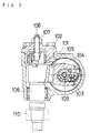
- a ball-screw power steering device 101 disclosed in Japanese Examined Publication Utility Model 61-302 shown in FIG.3 comprises a housing 102, a ball screw 109 rotatable according to steering operation, a ball nut 103 meshed with the ball screw 109 through balls, a rack 104 which is shaped on the ball nut 103, a sector gear 105 meshed with the rack 104, and an output shaft 106 which is united with the sector gear 105.
- a pitman arm 110 is fitted to the lower end of the output shaft 106.
- the pitman arm 110 is connected to steering road wheels through a link (omitted from the figure).
- hydraulic pressure according to the steering direction acts on the ball nut 103.
- a threaded shaft 107 is screwed into the upper portion of the housing 102.
- the lower portion of the threaded shaft 107 is connected to the upper portion of the output shaft 106 in a manner that the threaded shaft 107 is relatively rotatable around its own axis with respect to the output shaft 106 but that the threaded shaft 107 is relatively unmovable in its own axis direction with respect to the output shaft 106.
- the threaded shaft 107 has, on its top portion, an indentation 108 intended for use with a tool, so that the threaded shaft 107 can be rotated from upward. The rotation of the threaded shaft 107 thus causes the output shaft 106 to move in its own axis direction, with respect to the housing 102.
- the sector gear 105 also moves with respect to the housing 102, consequently adjusting the meshing between the sector gear 105 and the rack 104.
- the conventional steering device 101 in which the threaded shaft 107 is projected out of the housing 102, has a disadvantages as follows.
- mutual interference may take place between the threaded shaft 107 and other components.
- the other components prevent the threaded shaft 107 to rotate from upward.
- Mounting the threaded shaft 107 on the lower portion of the output shaft 106 may be considered to overcome such difficulties. Since a steering mechanism member such as a pitman arm 110 has to be mounted on the lower portion of the output shaft 106, the lower portion of the output shaft 106 needs to be exposed out of the housing. Therefore, such a conventional construction as a threaded shaft screwed into a housing cannot permit to mount the threaded shaft on the lower portion of the output shaft.
- the steering device comprises a housing, a rack movable according to steering operation, a sector gear meshed with the rack, an output shaft which is united with the sector gear, and a steering mechanism member which is mounted on one end of the output shaft, wherein the movement of the output shaft in its own axis direction with respect to the housing adjusts the meshing between the rack and the sector gear, a through hole is formed along the axis center line of the output shaft, a threaded shaft is inserted into the through hole, the threaded shaft is screwed into the output shaft, one end of the threaded shaft is accessible to rotate from a side where the steering mechanism member is mounted, and the other end of the threaded shaft is connected to the housing in a manner that the threaded shaft is rotatable around its own axis but that the threaded shaft is unmovable in its own axis direction.
- the output shaft is moved in its own axis direction, with respect to the housing, by rotating the threaded shaft from the side where the steering mechanism member is mounted.
- the resulting movement of the output shaft in its own axis direction relative to the housing adjusts the meshing between the rack and the sector gear.
- the above construction eliminates mutual interference between the threaded shaft and other components which are mounted on top of the steering device.
- the above construction also avoids, in rotating the threaded shaft, the physical difficulty presented by other components which are mounted on top of the steering device.
- the threaded shaft can be rotated for the adjustment from the side where the steering mechanism member is mounted.
- a head portion is formed on the other end of the threaded shaft, a retaining ring is fitted inside the housing, a ring is supported by the retaining ring, the threaded shaft is inserted through both the retaining ring and the ring, and the head portion of the threaded shaft is positioned between the housing and the ring.
- the housing is cast, and a steel member is provided between the head portion of the threaded shaft and the housing. The use of the cast housing lowers the material costs.
- the steel member provided between the head portion of the threaded shaft and the cast housing avoids wear of the cast housing by rubbing against the head portion of the threaded shaft.
- This wear resistant structure prevents the slack of the threaded shaft in its own axis direction from increasing, and the meshing between the rack and the sector gear is accurately adjusted.
- one end of the threaded shaft is exposed out of the output shaft, and the exposed portion of the threaded shaft has a locknut screwed onto it, wherein the locknut is pressed against the surface of the end of the output shaft in a manner that the locknut keeps the threaded shaft locked not to rotate.
- the meshing between the rack and the sector gear once properly adjusted is prevented from getting slack later.
- a bushing is provided between the external circumferential surface of the threaded shaft and the inner circumferential wall of the through hole.
- the bushing prevents the threaded shaft from inclining to the output shaft, and thus a smooth rotation of the threaded shaft is assured when adjusting the meshing between the rack and the sector gear.
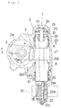
- FIG.1 is a cross-sectional view showing a ball-screw power steering device according to an embodiment of the present invention.
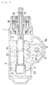
- FIG.2 is a cross-sectional view taken along II-II in FIG.1.
- FIG.3 is a cross-sectional view showing a conventional ball-screw power steering device.
- a ball-screw power steering device which comprises a housing 2, a ball screw 13, a ball nut 3 meshed with the ball screw 13 through balls 14, a rack 4 which is shaped on the ball nut 3, a sector gear 5 meshed with the rack 4, an output shaft 6 which is united with the sector gear 5, and a pitman arm 17 (a steering mechanism member) fitted to the lower portion of the output shaft 6 through serration 18.
- the teeth of the rack 4 and the teeth of the sector gear 5 are inclined with respect to each other.
- oil chambers 11 and 12 Formed inside the first housing 2a are oil chambers 11 and 12, both of which are separated by the ball nut 3.
- a rotary valve 16 is disposed around the external circumference of the input shaft 15.
- the rotary valve 16 may a known one (for example, the one disclosed in Japanese Examined Publication Utility Model 61-302).
- pressurized oil provided by a pump (omitted from the figure) is circulated to one of two oil chambers 11 and 12 according to the steering direction, and then drained from the other of two oil chambers 11 and 12 into an oil tank (omitted from the figure).
- the above hydraulic pressure acts on the ball nut 3 to move it in its own axis direction, adding an extra steering force in support of the steering action.
- a through hole 20 is formed along the axis center line of the output shaft 6.
- a threaded shaft 21 is inserted into the through hole 20; the threaded shaft 21 has, on its outer circumference, an externally threaded portion 21a, which is screwed into an internally threaded portion 20a formed on the inner wall of the through hole 20.
- the lower portion of the threaded shaft 21 is projected out of the lower end of the output shaft 6.
- the threaded shaft 21 has, on its lower end, an indentation 21b intended for use with a tool such as a hexagon wrench. This allows the threaded shaft 21 to be rotated from the side where the pitman arm 17 is mounted.
- a locknut 22 is screwed onto the lower portion of the threaded shaft 21.
- the upper end of the threaded shaft 21 is connected to the second housing 2b in a manner that the threaded shaft 21 is rotatable around its own axis but that the threaded shaft 21 is unmovable in its own axis direction.
- a retaining ring 25 is fitted in the upper inside portion of the second housing 2b, and a ring 26 is supported by the retaining ring 25.
- the threaded shaft 21 is inserted through the retaining ring 25 and the ring 26, and the head portion 21c of the threaded shaft 21 is positioned between the second housing 2b and the ring 26.
- the head portion 21c of the threaded shaft 21 is in contact with the upper surface of the ring 26.
- a steel plate 27 is provided between the head portion 21c of the threaded shaft 21 and the second housing 2b.
- the head portion 21c of the threaded shaft 21 is in contact with the steel plate 27 in a manner which allows the threaded shaft 21 to be rotatable on its own axis.
- a small clearance may be allowed between the head portion 21c and the ring 26, as long as the clearance does not affect the adjustment of meshing between the rack 4 and the sector gear 5, and as long as the movement of the threaded shaft 21 in its own axis direction is substantially constrained against the housing 2.
- a bushing 30, provided between the external circumferential surface of the threaded shaft 21 and the inner circumferential wall of the through hole 20, prevents the threaded shaft 21 from inclining to the output shaft 6.
- the threaded shaft 21, screwed into the output shaft 6, is connected to the housing 2 in a manner that the threaded shaft 21 is rotatable around its own axis but that the threaded shaft 21 is unmovable in its own axis direction, and thus the rotation of the threaded shaft 21 causes the output shaft 6 to move in its own axis direction.
- This movement of the output shaft 6 works to modify the backlash between the rack 4 and the sector gear 5, thereby allowing the meshing between the rack 4 and the sector gear 5 to be adjusted.
- the threaded shaft 21 is accessible to rotate from downward, i.e., from the side where the pitman arm 17 is mounted; thus, no interference problem takes place between the threaded shaft 21 and other components mounted on top of the housing 2. Furthermore, other components mounted on top of the housing 2 present no physical difficulty in the operation of rotating the threaded shaft 21.
- the use of the cast housing 2 lowers the material costs.
- the steel plate 27 is provided between the head portion 21c of the threaded shaft 21 and the cast housing 2, the cast housing 2 is prevented from wear by rubbing against the head portion 21c of the threaded shaft 21.
- This wear resistant structure prevents the slack of the threaded shaft 21 in its own axis direction from increasing, and the meshing between the rack 4 and the sector gear 5 is accurately adjusted.
- the bushing 30 prevents the threaded shaft 21 from inclining to the axis of the output shaft 6, thus a smooth rotation of the threaded shaft 21 is assured when adjusting the meshing between the rack 4 and the sector gear 5.
- the present invention is not limited to the above- mentioned embodiment.
- the present invention is applied to a power steering device, the present invention may be applied to other type of device such as a manual steering device.
Landscapes
- Engineering & Computer Science (AREA)
- Chemical & Material Sciences (AREA)
- Combustion & Propulsion (AREA)
- Transportation (AREA)
- Mechanical Engineering (AREA)
- Power Steering Mechanism (AREA)
- Gears, Cams (AREA)
- Steering Controls (AREA)
- Transmission Devices (AREA)
Applications Claiming Priority (2)
| Application Number | Priority Date | Filing Date | Title |
|---|---|---|---|
| JP1991036082U JP2535083Y2 (ja) | 1991-04-19 | 1991-04-19 | ステアリング装置 |
| JP36082/91U | 1991-04-19 |
Publications (3)
| Publication Number | Publication Date |
|---|---|
| EP0509336A2 true EP0509336A2 (de) | 1992-10-21 |
| EP0509336A3 EP0509336A3 (en) | 1993-09-01 |
| EP0509336B1 EP0509336B1 (de) | 1995-07-12 |
Family
ID=12459825
Family Applications (1)
| Application Number | Title | Priority Date | Filing Date |
|---|---|---|---|
| EP92105724A Expired - Lifetime EP0509336B1 (de) | 1991-04-19 | 1992-04-02 | Lenkvorrichtung |
Country Status (5)
| Country | Link |
|---|---|
| US (1) | US5211069A (de) |
| EP (1) | EP0509336B1 (de) |
| JP (1) | JP2535083Y2 (de) |
| KR (1) | KR0144446B1 (de) |
| DE (1) | DE69203375T2 (de) |
Families Citing this family (7)
| Publication number | Priority date | Publication date | Assignee | Title |
|---|---|---|---|---|
| US5855142A (en) * | 1996-12-13 | 1999-01-05 | General Motors Corporation | Retainer for ball screw crossover tube |
| US5953960A (en) * | 1997-03-11 | 1999-09-21 | Trw Inc. | Steering apparatus |
| US6070483A (en) * | 1997-08-01 | 2000-06-06 | Trw Inc. | Lash adjustment assembly |
| US6076418A (en) * | 1998-10-21 | 2000-06-20 | Trw Inc. | Lash adjustment mechanism |
| US6065561A (en) * | 1998-11-23 | 2000-05-23 | Howard; Durrell U. | Power steering system with controlled centering |
| US20090165679A1 (en) * | 2007-12-28 | 2009-07-02 | Hni Technologies, Inc. | Technology port |
| FR3005130B1 (fr) * | 2013-04-24 | 2015-04-17 | Sonceboz Sa | Actionneur electrique a tige filetee |
Family Cites Families (6)
| Publication number | Priority date | Publication date | Assignee | Title |
|---|---|---|---|---|
| US2605854A (en) * | 1948-11-18 | 1952-08-05 | Bendix Aviat Corp | Steering mechanism |
| DE1067317B (de) * | 1957-10-21 | 1959-10-15 | ||
| US3170338A (en) * | 1962-12-20 | 1965-02-23 | Ford Motor Co | Steering gear |
| ES451571A1 (es) * | 1976-09-16 | 1977-10-16 | Bendiberica Sa | Perfeccionamientos en mecanismos de servodireccion para ve- hiculos. |
| EP0003678A1 (de) * | 1978-02-07 | 1979-08-22 | CAM GEARS Limited | Lenkgetriebe |
| JPS61302A (ja) * | 1984-06-13 | 1986-01-06 | 月星化成株式会社 | 帯電防止射出成形靴の製造法 |
-
1991
- 1991-04-19 JP JP1991036082U patent/JP2535083Y2/ja not_active Expired - Lifetime
-
1992
- 1992-03-31 US US07/861,019 patent/US5211069A/en not_active Expired - Fee Related
- 1992-04-02 EP EP92105724A patent/EP0509336B1/de not_active Expired - Lifetime
- 1992-04-02 DE DE69203375T patent/DE69203375T2/de not_active Expired - Fee Related
- 1992-04-18 KR KR1019920006537A patent/KR0144446B1/ko not_active Expired - Fee Related
Also Published As
| Publication number | Publication date |
|---|---|
| JP2535083Y2 (ja) | 1997-05-07 |
| JPH04123776U (ja) | 1992-11-10 |
| US5211069A (en) | 1993-05-18 |
| DE69203375D1 (de) | 1995-08-17 |
| KR920019599A (ko) | 1992-11-19 |
| EP0509336A3 (en) | 1993-09-01 |
| EP0509336B1 (de) | 1995-07-12 |
| KR0144446B1 (ko) | 1998-08-01 |
| DE69203375T2 (de) | 1996-03-21 |
Similar Documents
| Publication | Publication Date | Title |
|---|---|---|
| JP3799236B2 (ja) | 電動式動力舵取装置 | |
| US6705176B2 (en) | Electric power steering apparatus | |
| US4322986A (en) | Variable ratio rack and pinion gear | |
| US20120241246A1 (en) | Electric power steering device | |
| US20230406403A1 (en) | Steering actuator and initial free play adjustment method between reducer gears of steering actuator | |
| EP0509336B1 (de) | Lenkvorrichtung | |
| JPH0579546B2 (de) | ||
| KR20040047710A (ko) | 전동파워 스티어링 장치 | |
| US4224833A (en) | Rack and pinion steering, especially for motor vehicles | |
| US11124223B2 (en) | Bearing for a ball nut assembly of a vehicle power steering assembly | |
| EP4582329A1 (de) | Lenkvorrichtung | |
| US8336412B1 (en) | Electric power steering apparatus | |
| JP2002274397A (ja) | 電動パワーステアリング装置 | |
| US20050061575A1 (en) | Electric power steering apparatus | |
| JP4016815B2 (ja) | 電動パワーステアリング装置 | |
| US6070483A (en) | Lash adjustment assembly | |
| US6418808B1 (en) | Power steering apparatus | |
| CN115771558A (zh) | 用于机动车的转向系统的助力驱动装置和机动车的转向系统 | |
| US5487439A (en) | Rear wheel steering device | |
| JP3560779B2 (ja) | プレス機械のダイハイト調節装置 | |
| JP6970572B2 (ja) | 転舵機能付ハブユニットおよびそれを備えた車両 | |
| JPH0585373A (ja) | 電動後輪操舵装置 | |
| JPS621007Y2 (de) | ||
| CN222859530U (zh) | 转向器、转向系统和车辆 | |
| JPH07237551A (ja) | 電動式パワーステアリング装置 |
Legal Events
| Date | Code | Title | Description |
|---|---|---|---|
| PUAI | Public reference made under article 153(3) epc to a published international application that has entered the european phase |
Free format text: ORIGINAL CODE: 0009012 |
|
| AK | Designated contracting states |
Kind code of ref document: A2 Designated state(s): DE FR GB |
|
| PUAL | Search report despatched |
Free format text: ORIGINAL CODE: 0009013 |
|
| AK | Designated contracting states |
Kind code of ref document: A3 Designated state(s): DE FR GB |
|
| 17P | Request for examination filed |
Effective date: 19930816 |
|
| 17Q | First examination report despatched |
Effective date: 19941018 |
|
| GRAA | (expected) grant |
Free format text: ORIGINAL CODE: 0009210 |
|
| AK | Designated contracting states |
Kind code of ref document: B1 Designated state(s): DE FR GB |
|
| ET | Fr: translation filed | ||
| REF | Corresponds to: |
Ref document number: 69203375 Country of ref document: DE Date of ref document: 19950817 |
|
| PLBE | No opposition filed within time limit |
Free format text: ORIGINAL CODE: 0009261 |
|
| STAA | Information on the status of an ep patent application or granted ep patent |
Free format text: STATUS: NO OPPOSITION FILED WITHIN TIME LIMIT |
|
| 26N | No opposition filed | ||
| REG | Reference to a national code |
Ref country code: GB Ref legal event code: IF02 |
|
| PGFP | Annual fee paid to national office [announced via postgrant information from national office to epo] |
Ref country code: GB Payment date: 20030402 Year of fee payment: 12 |
|
| PGFP | Annual fee paid to national office [announced via postgrant information from national office to epo] |
Ref country code: FR Payment date: 20030408 Year of fee payment: 12 |
|
| PGFP | Annual fee paid to national office [announced via postgrant information from national office to epo] |
Ref country code: DE Payment date: 20030409 Year of fee payment: 12 |
|
| PG25 | Lapsed in a contracting state [announced via postgrant information from national office to epo] |
Ref country code: GB Free format text: LAPSE BECAUSE OF NON-PAYMENT OF DUE FEES Effective date: 20040402 |
|
| PG25 | Lapsed in a contracting state [announced via postgrant information from national office to epo] |
Ref country code: DE Free format text: LAPSE BECAUSE OF NON-PAYMENT OF DUE FEES Effective date: 20041103 |
|
| GBPC | Gb: european patent ceased through non-payment of renewal fee | ||
| PG25 | Lapsed in a contracting state [announced via postgrant information from national office to epo] |
Ref country code: FR Free format text: LAPSE BECAUSE OF NON-PAYMENT OF DUE FEES Effective date: 20041231 |
|
| REG | Reference to a national code |
Ref country code: FR Ref legal event code: ST |