EP0510023B1 - Dispositif de reperage de la presence d'un vehicule au moyen d'un systeme a ultrasons - Google Patents
Dispositif de reperage de la presence d'un vehicule au moyen d'un systeme a ultrasons Download PDFInfo
- Publication number
- EP0510023B1 EP0510023B1 EP91901570A EP91901570A EP0510023B1 EP 0510023 B1 EP0510023 B1 EP 0510023B1 EP 91901570 A EP91901570 A EP 91901570A EP 91901570 A EP91901570 A EP 91901570A EP 0510023 B1 EP0510023 B1 EP 0510023B1
- Authority
- EP
- European Patent Office
- Prior art keywords
- sensors
- sensor
- traffic lane
- accord
- external sensors
- Prior art date
- Legal status (The legal status is an assumption and is not a legal conclusion. Google has not performed a legal analysis and makes no representation as to the accuracy of the status listed.)
- Expired - Lifetime
Links
- 238000001514 detection method Methods 0.000 claims description 13
- 230000000737 periodic effect Effects 0.000 abstract 1
- 238000002604 ultrasonography Methods 0.000 description 10
- 238000000034 method Methods 0.000 description 5
- 230000005540 biological transmission Effects 0.000 description 4
- 230000005855 radiation Effects 0.000 description 3
- 230000032683 aging Effects 0.000 description 2
- 238000013461 design Methods 0.000 description 2
- 238000011161 development Methods 0.000 description 2
- 230000018109 developmental process Effects 0.000 description 2
- 238000002592 echocardiography Methods 0.000 description 2
- 238000011156 evaluation Methods 0.000 description 2
- 235000013410 fast food Nutrition 0.000 description 2
- 238000009423 ventilation Methods 0.000 description 2
- 238000012935 Averaging Methods 0.000 description 1
- 230000009286 beneficial effect Effects 0.000 description 1
- 150000001875 compounds Chemical class 0.000 description 1
- 238000011109 contamination Methods 0.000 description 1
- 230000008878 coupling Effects 0.000 description 1
- 238000010168 coupling process Methods 0.000 description 1
- 238000005859 coupling reaction Methods 0.000 description 1
- 238000013016 damping Methods 0.000 description 1
- 238000004382 potting Methods 0.000 description 1
- 238000001028 reflection method Methods 0.000 description 1
- 230000035945 sensitivity Effects 0.000 description 1
- 238000000926 separation method Methods 0.000 description 1
- 230000001960 triggered effect Effects 0.000 description 1
- 239000002699 waste material Substances 0.000 description 1
Images
Classifications
-
- G—PHYSICS
- G01—MEASURING; TESTING
- G01S—RADIO DIRECTION-FINDING; RADIO NAVIGATION; DETERMINING DISTANCE OR VELOCITY BY USE OF RADIO WAVES; LOCATING OR PRESENCE-DETECTING BY USE OF THE REFLECTION OR RERADIATION OF RADIO WAVES; ANALOGOUS ARRANGEMENTS USING OTHER WAVES
- G01S15/00—Systems using the reflection or reradiation of acoustic waves, e.g. sonar systems
- G01S15/87—Combinations of sonar systems
-
- G—PHYSICS
- G01—MEASURING; TESTING
- G01S—RADIO DIRECTION-FINDING; RADIO NAVIGATION; DETERMINING DISTANCE OR VELOCITY BY USE OF RADIO WAVES; LOCATING OR PRESENCE-DETECTING BY USE OF THE REFLECTION OR RERADIATION OF RADIO WAVES; ANALOGOUS ARRANGEMENTS USING OTHER WAVES
- G01S15/00—Systems using the reflection or reradiation of acoustic waves, e.g. sonar systems
- G01S15/02—Systems using the reflection or reradiation of acoustic waves, e.g. sonar systems using reflection of acoustic waves
- G01S15/04—Systems determining presence of a target
-
- G—PHYSICS
- G01—MEASURING; TESTING
- G01S—RADIO DIRECTION-FINDING; RADIO NAVIGATION; DETERMINING DISTANCE OR VELOCITY BY USE OF RADIO WAVES; LOCATING OR PRESENCE-DETECTING BY USE OF THE REFLECTION OR RERADIATION OF RADIO WAVES; ANALOGOUS ARRANGEMENTS USING OTHER WAVES
- G01S7/00—Details of systems according to groups G01S13/00, G01S15/00, G01S17/00
- G01S7/52—Details of systems according to groups G01S13/00, G01S15/00, G01S17/00 of systems according to group G01S15/00
- G01S7/521—Constructional features
Definitions
- the invention relates to a device and a method for detecting the presence of a vehicle by means of an ultrasound device.
- DE-A-36 21 819 a method and a device for measuring distance in air by means of ultrasound is known, this device is also used to detect the presence of vehicles. It uses the pulse reflection method to periodically emit an ultrasonic pulse from the sensor, the reflections of which are received again by the same sensor.
- a vehicle-resident ultrasound device which emits a warning signal when the distance to a vehicle in front differs a minimum distance. This is intended to counteract rear-end collisions.
- the ultrasound device has three sensors, namely a central, transmitting sensor and two external, receiving sensors arranged at the same distance from it.
- a coincidence circuit is provided. An output signal is only given if both external sensors receive an ultrasonic signal at the same time.
- Another on-board distance measuring device of this type for a motor vehicle is known from DE-A-34 20 004. It has three sensors which are periodically operated alternately in such a way that in a first operating mode each sensor receives the ultrasound signal emitted by it and in a second operating mode at least one sensor receives and processes the ultrasound signals emitted by at least one other sensor. A warning device is activated if there is a predeterminable deviation in the runtimes in the two operating modes.
- the purpose of the device of the type mentioned at the outset is that a presence signal is emitted as long as a vehicle, in particular a motor vehicle, is in a predetermined area. It is intended for all systems in which a vehicle is on a predetermined lane, in particular a lane, and a person or machine is to be informed that a vehicle is within the selected area.
- the device can be used for car switches, entrance and exit stations of toll roads, bridges and the like, order pillars of fast food restaurants, etc.
- the device should not only, as is the case for other applications, eg. B. at traffic light controls, traffic counts, etc. is sufficient to give an impulse while a vehicle passes the device, it is not important to the exact spatial assignment between device and vehicle, but it should be given with certainty and always a presence signal as long as a vehicle is partially or entirely within a predetermined detection range.
- the invention is based on the object of developing the previously known device or the previously known method in such a way that, regardless of the shape and design of the vehicle, a positive presence signal is certainly present is output when and as long as a vehicle is within a detection area located in front of the ultrasound device.
- this object is achieved in that a central sensor and in each case at the same distance from this central sensor and at the greatest possible, in each case the same distance from one another, at least two external sensors are arranged, that the external sensors are connected and operated with equal priority, and that either the central sensor as the receiving sensor and the outer sensors as the transmitting sensors are connected, or vice versa.
- the invention makes use of the knowledge that each sensor receives or transmits in the spatial area of a club.
- the at least two transmitting (claim 2) or at least two receiving (claim 1) sensors ensure that reflections from inclined surfaces, from the area of ventilation slots, the area of the fenders, the door handles, the tires etc. are also detected .
- the largest possible echo of an area that is exactly perpendicular to the main beam of the at least one transmitting sensor is deliberately omitted; on the contrary, in the arrangement according to the invention the case that the main beam of a transmitting sensor is in the main receiving direction of a receiving sensor practically never occurs is reflected.
- marginal rays that are not detected by the previously known device are taken into account and, in this respect, reflections from inclined surfaces that cannot be detected by the previously known device can be detected.
- the division of the sensors into transmitting and receiving sensors and the spatial separation of these sensors preclude a direct or direct coupling of the transmission signal into the receiving channel. This simplifies the receiver circuit; its input does not have to be large signal-proof, which in turn improves the reliability and accuracy of the reception channel.
- the at least three sensors are arranged in a common housing and embedded in an elastic mass which is not resonant at the frequency used.
- the mechanical part of the device is easy to arrange and easy to use.
- the distance between the outer sensors and the central sensor be at least 5%, preferably at least 10% of the distance at which the vehicles to be detected are expected.
- the device according to the invention always covers only a partial area of an entire vehicle. In the above-mentioned distance range, a reflection of the usually occurring configurations of the body or chassis of a motor vehicle is achieved.
- the dimensions mentioned are particularly suitable for lateral detection (transverse to the direction of travel) of a vehicle. Cyclists, motorcyclists and scooters, etc. are also included in the selected arrangement.
- the height above the level at which the vehicles roll is 20 to 80, preferably 40 to 60 cm. In this area, a reliable registration of all common vehicles is achieved.
- the sensors are arranged vertically one above the other in an advantageous development. This takes into account the fact that body parts and other parts that run obliquely or curved in typical vehicles typically run parallel to the direction of travel of the vehicle and less frequently at an angle to this direction of travel.
- the motor vehicles After all, it has proven to be beneficial on the other Side of the detection area and outside the lane for the motor vehicles to arrange a reflector in the main beam direction of the sensors, which always delivers a reflection when there is no object in the detection area.
- the echo received by it is distinguished from the echoes of vehicles to be detected in that it arrives at a later point in time.
- the reflector enables a constant check of the device. Furthermore, automatic compensation of influencing variables, e.g. B. in the rain, with increasing damping due to contamination of the sensors, with aging of individual components, etc.
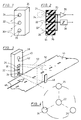
- Figures 1 to 3 show a first embodiment of the device for detecting the presence of a vehicle using ultrasonic sensors.
- a housing 20 In a housing 20 are vertically and evenly one above the other A total of three sensors for ultrasound are arranged, it is a central sensor 22 and an outer sensor 24, 26 above and below each.
- Commercially available piezo oscillators are used as sensors 22 to 26, which operate at a frequency of 40 KHz.
- the central sensor 22 is operated as a transmitter and is connected to a transmitter circuit 28.
- the two outer sensors 24, 26 are connected in parallel and connected to an input amplifier 28 of a reception channel (not shown further here).
- the two outer sensors 24, 26 are connected to the transmitter circuit 28 and work as transmitting sensors, in this case the central sensor 22 is responsible for receiving the reflected ultrasound signals, it is connected to the input amplifier 30.
- the central sensor 22 is responsible for receiving the reflected ultrasound signals, it is connected to the input amplifier 30.
- the front surfaces of the three sensors 22 to 26 are in the same plane. Their main beam directions 32, which proceed perpendicularly from the respective front surface, run parallel to one another.
- Each sensor 22 to 26 has a radiation lobe 34, which is indicated by a dashed line (very greatly reduced) in FIG. 2. According to the invention, the radiation lobes 34 of adjacent sensors are superimposed.
- the sensors 22 to 26 are embedded in an elastic mass 36 which on the one hand gives them a mechanical hold, encloses them up to the front surface and on the other hand allows an oscillating movement.
- a plastic potting compound is used as mass 36, which in the finished state has a Shore hardness of 40.
- the sensors 22 to 26 are electrically connected with flexible connecting wires, in particular strands.
- FIG 3 shows the arrangement of a housing according to FIGS. 1 and 2 in a speech column 38, as is the case, for example, with the ordering stations is used for car switches in fast food restaurants.
- a listening and speaking unit 40 and a call button 42 are provided in the window height of a car.
- the housing 20 is arranged underneath and flush with the surface in accordance with FIGS. 1 and 2, it is 170 mm high and 70 mm wide.
- the three sensors 22 to 26 can be seen.
- the talk pillar 38 is located on the side of a lane 44 for the vehicles to be recognized.
- the central sensor 22 is arranged at a height of approximately 40 cm above the surface of the lane, its main beam direction runs parallel to the surface of the lane 44 and at right angles to a direction of travel 46.
- This main radiation direction 32 is on the other side of the lane 44, the Speech column 38 exactly opposite, a reflector 48, which will be discussed later.
- the possible detection zone 50 of the device according to the invention is indicated by dash-dotted lines starting from the front of the housing 20. Objects that are within the zone 50 shown can be detected.
- known electronic measures namely by a time gate, it is achieved that only those reflections of a transmitted pulse can deliver a positive presence signal in which the reflection takes place within the detection range 52.
- the time limit closer to the housing 20 can be dispensed with, but not the time limit for longer periods. It prevents traffic on other lanes etc., for example a second lane to the right of lane 44 in FIG. 3, from being detected.
- an amplitude threshold can be provided, which ensures that only larger objects that deliver a sufficiently large echo signal are actually detected. This prevents the device from being triggered by small objects.
- an averaging over several pulses is provided in the electronic evaluation circuit, so that one or a few interference signals do not yet give a presence indicator.
- the reflector 48 By the reflector 48 is outside the time range of the detection range 42 an echo is delivered which always arrives at the two receiving sensors 24, 26 at a predetermined point in time. A separate time window is provided for its evaluation. On the basis of the echo of the reflector 48, a permanent and automatic function check of the entire device is possible. Signs of aging of individual components can be compensated by, for example, increasing the transmission power in the event of waste. Furthermore, the device can be switched to idle mode after a certain number of received echoes originating from the reflector 48, in which, for example, the clock frequency of the transmission of ultrasound signals is reduced by the central sensor 22, for example reduced to a quarter. This reduction is canceled again as soon as an object has been found within the detection area 52.
- a heater 54 e.g. a power transistor operated in the power loss range is provided inside the housing 20 .
- the heater is assigned a control unit, not shown, which comprises a temperature sensor arranged in the housing 20.
- FIG. 4 finally shows the arrangement of three receiving (or in the alternative: transmitting) sensors 24, 25, 26, which are arranged on an arc around the central, transmitting (or in the alternative: receiving) sensor 22.
- the radius of the circular arc on which the outer sensors 24 to 26 are arranged is matched to the distance between the detection area 52 and the housing 20, and is at least 5% of this distance.
- the outer sensors 24 to 26 are arranged at the same pitch angles on the circular arc around the central sensor 22.
Landscapes
- Engineering & Computer Science (AREA)
- Radar, Positioning & Navigation (AREA)
- Remote Sensing (AREA)
- Physics & Mathematics (AREA)
- Computer Networks & Wireless Communication (AREA)
- General Physics & Mathematics (AREA)
- Acoustics & Sound (AREA)
- Measurement Of Velocity Or Position Using Acoustic Or Ultrasonic Waves (AREA)
- Traffic Control Systems (AREA)
Abstract
Claims (9)
- Dispositif de repérage de la présence d'un véhicule se trouvant sur une bande de chaussée (44) au moyen d'un système à ultrasons installé sur le côté de la bande de chaussée (44), ce système possédant un capteur centré (22) et au moins deux capteurs externes (24, 26) ayant respectivement le même écartement par rapport au capteur centré (22) et un écartement si possible grand et identique entre eux ainsi qu'un circuit émetteur et récepteur électronique (28, 30) affecté à l'un de ces capteurs (22, 24, 26), ces derniers (22 à 26) étant logés dans un boîtier commun (20), les capteurs externes (24, 26) étant couplés parallèlement ou en série et le capteur centré (22) émettant périodiquement des impulsions dont les réflexions sont captées par les capteurs externes (24, 26) et évaluées par le circuit (28, 30), celui-ci générant un signal de présence positif lorsque des réflexions se produisent dans une zone de détection (52) qui est limitée par la largeur de la bande de chaussée (44) et que ces réflexions sont captées au moins par un capteur externe (24, 26).
- Dispositif de repérage de la présence d'un véhicule se trouvant sur une bande de chaussée (44) au moyen d'un système à ultrasons installé sur le côté de la bande de chaussée (44), ce système possédant un capteur centré (22) et au moins deux capteurs externes (24, 26) ayant respectivement le même écartement par rapport au capteur centré (22) et un écartement si possible grand et identique entre eux ainsi qu'un circuit émetteur et récepteur électronique (28, 30) affecté à l'un de ces capteurs (22, 24, 26), ces derniers (22 à 26) étant logés dans un boîtier commun (20), les capteurs externes (24, 26) étant couplés parallèlement ou en série et émettant des impulsions périodiques dont les réflexions sont captées par le capteur centré (22) et évaluées par le circuit (28, 30), celui-ci générant un signal de présence positif lorsque des réflexions se produisent dans une zone de détection (52) qui est limitée par la largeur de la bande de chaussée (44) et que ces réflexions sont captées par le capteur centré (22).
- Dispositif selon la revendication 1 ou 2, caractérisé par le fait que les sens du faisceau principal (32) de tous les capteurs (22 à 26) présentent une orientation parallèle entre eux.
- Dispositif selon la revendication 1 ou 2, caractérisé par le fait que les capteurs logés dans le boîtier (20) se trouvent dans une masse élastique (36) qui n'est pas résonnante.
- Dispositif selon la revendication 1 ou 2, caractérisé par le fait que l'écartement des capteurs externes (24, 26) par rapport au capteur centré (22) s'élève au moins à 5 %, de préférence au moins à 10 %, de l'écartement auquel les véhicules sont attendus.
- Dispositif selon la revendication 1 ou 2, caractérisé par le fait qu'une moyenne sur plusieurs périodes est effectuée dans le circuit récepteur (30).
- Dispositif selon la revendication 1 ou 2, caractérisé par le fait qu'une porte de temps est prévue dans le circuit récepteur (30) dont la limite inférieure se situe à zéro ou au-dessus de zéro et dont la limite supérieure est inférieure au temps qui est nécessaire au son pour parcourir une fois le trajet perpendiculaire à la bande de chaussée 44 et revenir à son point de départ.
- Dispositif selon la revendication 1 ou 2, caractérisé par le fait que, s'il existe deux capteurs externes (24, 26), les trois capteurs (22 à 26) sont disposés l'un au-dessus de l'autre à la verticale.
- Dispositif selon la revendication 1 ou 2, caractérisé par le fait que le capteur centré (22) se trouve à 20-80 cm au-dessus du niveau de la bande de chaussée (44), de préférence 40 à 60 cm au-dessus de ce niveau.
Priority Applications (1)
| Application Number | Priority Date | Filing Date | Title |
|---|---|---|---|
| AT91901570T ATE104440T1 (de) | 1990-01-12 | 1991-01-04 | Vorrichtung zum erkennen der anwesenheit eines fahrzeugs mittels einer ultraschallvorrichtung. |
Applications Claiming Priority (3)
| Application Number | Priority Date | Filing Date | Title |
|---|---|---|---|
| DE4000698 | 1990-01-12 | ||
| DE4000698A DE4000698A1 (de) | 1990-01-12 | 1990-01-12 | Vorrichtung und verfahren zum erkennen der anwesenheit eines fahrzeugs mittels einer ultraschallvorrichtung |
| PCT/DE1991/000001 WO1991010920A1 (fr) | 1990-01-12 | 1991-01-04 | Dispositif et procede de reperage de la presence d'un vehicule au moyen d'un systeme a ultrasons |
Publications (2)
| Publication Number | Publication Date |
|---|---|
| EP0510023A1 EP0510023A1 (fr) | 1992-10-28 |
| EP0510023B1 true EP0510023B1 (fr) | 1994-04-13 |
Family
ID=6397928
Family Applications (1)
| Application Number | Title | Priority Date | Filing Date |
|---|---|---|---|
| EP91901570A Expired - Lifetime EP0510023B1 (fr) | 1990-01-12 | 1991-01-04 | Dispositif de reperage de la presence d'un vehicule au moyen d'un systeme a ultrasons |
Country Status (5)
| Country | Link |
|---|---|
| US (1) | US5263006A (fr) |
| EP (1) | EP0510023B1 (fr) |
| AU (1) | AU6978291A (fr) |
| DE (2) | DE4000698A1 (fr) |
| WO (1) | WO1991010920A1 (fr) |
Families Citing this family (21)
| Publication number | Priority date | Publication date | Assignee | Title |
|---|---|---|---|---|
| DE4338743C2 (de) * | 1993-11-12 | 2003-06-26 | Bosch Gmbh Robert | Verfahren und Vorrichtung zum Betrieb eines Ultraschallsensors |
| DE19747799B4 (de) * | 1997-10-30 | 2005-12-29 | Robert Bosch Gmbh | Verfahren für die Erhöhung der Reichweite von Sensoren |
| DE19842112B4 (de) * | 1998-09-07 | 2006-12-14 | Braun, Uwe Peter, Dipl.-Ing. | Einrichtung zur Einstellung und Steuerung der Beleuchtungsstärke von Kontrolleuchten |
| US6229455B1 (en) | 1999-01-15 | 2001-05-08 | Intelligent Devices, Inc. | Vehicle-detecting unit for use with electronic parking meter |
| JP2005151676A (ja) * | 2003-11-14 | 2005-06-09 | Mitsubishi Fuso Truck & Bus Corp | センサハーネスの固定構造 |
| JP2005217755A (ja) | 2004-01-29 | 2005-08-11 | Mitsubishi Electric Corp | 超音波センサ装置 |
| US20050264902A1 (en) * | 2004-05-07 | 2005-12-01 | Mark Rennick | Reflector mounted sensor system and method |
| US20070210935A1 (en) * | 2006-03-10 | 2007-09-13 | Intellipark, Llc | Electronic parking meter with vehicle detecting sensor |
| US8990098B2 (en) | 2008-04-30 | 2015-03-24 | Ecolab Inc. | Validated healthcare cleaning and sanitizing practices |
| US8639527B2 (en) | 2008-04-30 | 2014-01-28 | Ecolab Usa Inc. | Validated healthcare cleaning and sanitizing practices |
| PL2441063T3 (pl) | 2009-06-12 | 2015-08-31 | Ecolab Usa Inc | Monitorowanie przestrzegania higieny rąk |
| USRE48951E1 (en) | 2015-08-05 | 2022-03-01 | Ecolab Usa Inc. | Hand hygiene compliance monitoring |
| US9264151B1 (en) | 2009-07-29 | 2016-02-16 | Shopkick, Inc. | Method and system for presence detection |
| US8489112B2 (en) | 2009-07-29 | 2013-07-16 | Shopkick, Inc. | Method and system for location-triggered rewards |
| US8179240B1 (en) | 2009-07-31 | 2012-05-15 | Orefice Ryan M | Motorcycle detection and notification system and associated method |
| US20140210620A1 (en) | 2013-01-25 | 2014-07-31 | Ultraclenz Llc | Wireless communication for dispenser beacons |
| US10044448B2 (en) | 2011-05-18 | 2018-08-07 | Sparcq, Inc. | Sonic signaling communication for user devices |
| US20140118170A1 (en) * | 2012-10-29 | 2014-05-01 | Emx Industries Inc. | Vehicle detector |
| US11272815B2 (en) | 2017-03-07 | 2022-03-15 | Ecolab Usa Inc. | Monitoring modules for hand hygiene dispensers |
| US10529219B2 (en) | 2017-11-10 | 2020-01-07 | Ecolab Usa Inc. | Hand hygiene compliance monitoring |
| EP3900307A1 (fr) | 2018-12-20 | 2021-10-27 | Ecolab USA, Inc. | Routage adaptatif, communication en réseau bidirectionnel |
Family Cites Families (14)
| Publication number | Priority date | Publication date | Assignee | Title |
|---|---|---|---|---|
| US3046519A (en) * | 1959-10-28 | 1962-07-24 | Gen Railway Signal Co | Ultrasonic vehicle detection system |
| GB1313534A (en) * | 1970-05-06 | 1973-04-11 | Parke Davis & Co | Electroacoustic investigation apparatus |
| US3733580A (en) * | 1970-12-22 | 1973-05-15 | Pitney Bowes Inc | Acoustical sensing curtain |
| US3863196A (en) * | 1972-01-31 | 1975-01-28 | Dynamics Corp Massa Div | Acoustically activated proximity sensor switch |
| US4112419A (en) * | 1975-03-28 | 1978-09-05 | Hitachi, Ltd. | Apparatus for detecting the number of objects |
| ES471752A1 (es) * | 1977-07-15 | 1979-06-16 | Kraftwerk Union Ag | Dispositivo para la verificacion volumetrica de las paredes de las paredes de recipientes o tubos. |
| USRE30719E (en) * | 1978-08-02 | 1981-08-25 | Doorway safety device | |
| FR2478824A1 (fr) * | 1980-03-21 | 1981-09-25 | Thomson Csf | Systeme d'imagerie acoustique |
| EP0043396A1 (fr) * | 1980-07-09 | 1982-01-13 | Geoffrey Thomas Burling | Système indicateur de distance |
| FR2493528A1 (fr) * | 1980-11-04 | 1982-05-07 | Thomson Csf | Systeme de detection multivoies a emission diversifiee |
| DE3302886C2 (de) * | 1983-01-28 | 1985-06-20 | Dieter Dipl.-Ing. 6652 Bexbach Kiefer | Entfernungsmeßgerät |
| US4739860A (en) * | 1984-05-29 | 1988-04-26 | Nissan Motor Co., Ltd. | Ultrasonic rangefinder |
| DE3420004A1 (de) * | 1984-05-29 | 1985-12-05 | Bosch Gmbh Robert | Abstandsmessvorrichtung fuer kraftfahrzeuge |
| US4706227A (en) * | 1986-01-31 | 1987-11-10 | Overhead Door Corporation Of Texas | Acoustic obstruction detector and method |
-
1990
- 1990-01-12 DE DE4000698A patent/DE4000698A1/de not_active Withdrawn
-
1991
- 1991-01-04 AU AU69782/91A patent/AU6978291A/en not_active Abandoned
- 1991-01-04 EP EP91901570A patent/EP0510023B1/fr not_active Expired - Lifetime
- 1991-01-04 DE DE59101385T patent/DE59101385D1/de not_active Expired - Fee Related
- 1991-01-04 US US07/867,703 patent/US5263006A/en not_active Expired - Fee Related
- 1991-01-04 WO PCT/DE1991/000001 patent/WO1991010920A1/fr not_active Ceased
Also Published As
| Publication number | Publication date |
|---|---|
| WO1991010920A1 (fr) | 1991-07-25 |
| AU6978291A (en) | 1991-08-05 |
| DE59101385D1 (de) | 1994-05-19 |
| EP0510023A1 (fr) | 1992-10-28 |
| DE4000698A1 (de) | 1991-07-18 |
| US5263006A (en) | 1993-11-16 |
Similar Documents
| Publication | Publication Date | Title |
|---|---|---|
| EP0987563B1 (fr) | Méthode pour déterminer la distance de séparation d'un objet et un engin déplaçable, en particulier un véhicule motorisé | |
| DE4000698A1 (de) | Vorrichtung und verfahren zum erkennen der anwesenheit eines fahrzeugs mittels einer ultraschallvorrichtung | |
| DE3420004C2 (fr) | ||
| EP0970390B1 (fr) | Procede de determination de l'ecart vertical entre un objet et un dispositif a position variable | |
| EP1058126B1 (fr) | Dispositif de détection à distance | |
| DE4338743C2 (de) | Verfahren und Vorrichtung zum Betrieb eines Ultraschallsensors | |
| DE3207950C2 (fr) | ||
| EP1478547B1 (fr) | Procede de stationnement d'un vehicule | |
| DE19744185B4 (de) | Einrichtung zur Abstandsmessung mittels Ultraschall | |
| EP2048515B1 (fr) | Procédé pour déterminer et documenter des infractions à un feux de signalisation | |
| DE4127168C2 (de) | Signalverarbeitung zur Abstandsmessung | |
| DE19839942C2 (de) | Einparkhilfe für ein Kraftfahrzeug | |
| DE4023538A1 (de) | Kollisionswarneinrichtung | |
| DE3519254C2 (fr) | ||
| EP2778714A1 (fr) | Procédé d'enregistrement d'embouteillages dans une zone de feux de signalisation par le relevé des parties arrières à l'aide d'un radar | |
| DE4120397A1 (de) | Einrichtung zur messung mittels ultraschall | |
| EP3602119A1 (fr) | Procédé de détection d'un objet dans une zone environnante d'un véhicule automobile avec classification de l'objet, dispositif de détection à ultrasons et véhicule automobile | |
| DE19953007A1 (de) | Vorrichtung zur Verkehrsüberwachung von Straßen | |
| DE102015119658A1 (de) | Verfahren zum Erfassen eines Umgebungsbereichs eines Kraftfahrzeugs mit Objektklassifizierung, Steuereinrichtung, Fahrerassistenzsystem sowie Kraftfahrzeug | |
| EP2035858A1 (fr) | Capteur a ultrasons, vehicule a moteur le comprenant et procede pour le faire fonctionner | |
| EP3359975B1 (fr) | Capteur comprenant un ensemble ultrasonique monolithique | |
| EP1797459A1 (fr) | Capteur infrarouge de mesure de place de stationnement et de surveillance de champ pour un vehicule | |
| DE4218041C2 (de) | Ultraschallsensor mit Funktionsüberwachung | |
| DE10225894A1 (de) | Verfahren zur Bestimmung eines Abstandes zwischen zwei im Wesentlichen in einer Ebene sich befindenden Gegenständen auf Basis synthetischer Apertur | |
| EP1333296B1 (fr) | Procédé pour déterminer la distance entre deux objets situés dans le même plan |
Legal Events
| Date | Code | Title | Description |
|---|---|---|---|
| PUAI | Public reference made under article 153(3) epc to a published international application that has entered the european phase |
Free format text: ORIGINAL CODE: 0009012 |
|
| AK | Designated contracting states |
Kind code of ref document: A1 Designated state(s): AT BE CH DE FR GB LI |
|
| 17P | Request for examination filed |
Effective date: 19920725 |
|
| 17Q | First examination report despatched |
Effective date: 19930928 |
|
| GRAA | (expected) grant |
Free format text: ORIGINAL CODE: 0009210 |
|
| AK | Designated contracting states |
Kind code of ref document: B1 Designated state(s): AT BE CH DE FR GB LI |
|
| REF | Corresponds to: |
Ref document number: 104440 Country of ref document: AT Date of ref document: 19940415 Kind code of ref document: T |
|
| REF | Corresponds to: |
Ref document number: 59101385 Country of ref document: DE Date of ref document: 19940519 |
|
| GBT | Gb: translation of ep patent filed (gb section 77(6)(a)/1977) |
Effective date: 19940621 |
|
| ET | Fr: translation filed | ||
| PLBE | No opposition filed within time limit |
Free format text: ORIGINAL CODE: 0009261 |
|
| STAA | Information on the status of an ep patent application or granted ep patent |
Free format text: STATUS: NO OPPOSITION FILED WITHIN TIME LIMIT |
|
| 26N | No opposition filed | ||
| PGFP | Annual fee paid to national office [announced via postgrant information from national office to epo] |
Ref country code: FR Payment date: 19991216 Year of fee payment: 10 |
|
| PGFP | Annual fee paid to national office [announced via postgrant information from national office to epo] |
Ref country code: DE Payment date: 19991217 Year of fee payment: 10 |
|
| PGFP | Annual fee paid to national office [announced via postgrant information from national office to epo] |
Ref country code: AT Payment date: 19991223 Year of fee payment: 10 |
|
| PGFP | Annual fee paid to national office [announced via postgrant information from national office to epo] |
Ref country code: GB Payment date: 19991224 Year of fee payment: 10 |
|
| PGFP | Annual fee paid to national office [announced via postgrant information from national office to epo] |
Ref country code: CH Payment date: 19991228 Year of fee payment: 10 |
|
| PGFP | Annual fee paid to national office [announced via postgrant information from national office to epo] |
Ref country code: BE Payment date: 20000630 Year of fee payment: 10 |
|
| PG25 | Lapsed in a contracting state [announced via postgrant information from national office to epo] |
Ref country code: GB Free format text: LAPSE BECAUSE OF NON-PAYMENT OF DUE FEES Effective date: 20010104 Ref country code: AT Free format text: LAPSE BECAUSE OF NON-PAYMENT OF DUE FEES Effective date: 20010104 |
|
| PG25 | Lapsed in a contracting state [announced via postgrant information from national office to epo] |
Ref country code: LI Free format text: LAPSE BECAUSE OF NON-PAYMENT OF DUE FEES Effective date: 20010131 Ref country code: CH Free format text: LAPSE BECAUSE OF NON-PAYMENT OF DUE FEES Effective date: 20010131 Ref country code: BE Free format text: LAPSE BECAUSE OF NON-PAYMENT OF DUE FEES Effective date: 20010131 |
|
| BERE | Be: lapsed |
Owner name: HERMESMEYER ALEXANDER C. Effective date: 20010131 |
|
| GBPC | Gb: european patent ceased through non-payment of renewal fee |
Effective date: 20010104 |
|
| REG | Reference to a national code |
Ref country code: CH Ref legal event code: PL |
|
| PG25 | Lapsed in a contracting state [announced via postgrant information from national office to epo] |
Ref country code: FR Free format text: LAPSE BECAUSE OF NON-PAYMENT OF DUE FEES Effective date: 20010928 |
|
| PG25 | Lapsed in a contracting state [announced via postgrant information from national office to epo] |
Ref country code: DE Free format text: LAPSE BECAUSE OF NON-PAYMENT OF DUE FEES Effective date: 20011101 |
|
| REG | Reference to a national code |
Ref country code: FR Ref legal event code: ST |