EP0510077B1 - Systeme preventif d'entretien de canalisations submergees - Google Patents
Systeme preventif d'entretien de canalisations submergees Download PDFInfo
- Publication number
- EP0510077B1 EP0510077B1 EP91903002A EP91903002A EP0510077B1 EP 0510077 B1 EP0510077 B1 EP 0510077B1 EP 91903002 A EP91903002 A EP 91903002A EP 91903002 A EP91903002 A EP 91903002A EP 0510077 B1 EP0510077 B1 EP 0510077B1
- Authority
- EP
- European Patent Office
- Prior art keywords
- pipe
- intake pipe
- feed pipe
- feed
- intake
- Prior art date
- Legal status (The legal status is an assumption and is not a legal conclusion. Google has not performed a legal analysis and makes no representation as to the accuracy of the status listed.)
- Expired - Lifetime
Links
- 238000012423 maintenance Methods 0.000 title description 2
- 239000000126 substance Substances 0.000 claims abstract description 41
- 238000000034 method Methods 0.000 claims description 7
- 239000007788 liquid Substances 0.000 claims 3
- XLYOFNOQVPJJNP-UHFFFAOYSA-N water Substances O XLYOFNOQVPJJNP-UHFFFAOYSA-N 0.000 description 22
- 241000237536 Mytilus edulis Species 0.000 description 12
- 235000020638 mussel Nutrition 0.000 description 12
- 241000193901 Dreissena polymorpha Species 0.000 description 10
- 239000000463 material Substances 0.000 description 5
- 239000002184 metal Substances 0.000 description 5
- 230000009972 noncorrosive effect Effects 0.000 description 5
- 239000003643 water by type Substances 0.000 description 5
- 229910000831 Steel Inorganic materials 0.000 description 4
- 239000010959 steel Substances 0.000 description 4
- 241000894007 species Species 0.000 description 3
- ZAMOUSCENKQFHK-UHFFFAOYSA-N Chlorine atom Chemical compound [Cl] ZAMOUSCENKQFHK-UHFFFAOYSA-N 0.000 description 2
- 241000237852 Mollusca Species 0.000 description 2
- 229910052801 chlorine Inorganic materials 0.000 description 2
- 239000000460 chlorine Substances 0.000 description 2
- 230000035558 fertility Effects 0.000 description 2
- 235000013305 food Nutrition 0.000 description 2
- 238000009434 installation Methods 0.000 description 2
- 239000000758 substrate Substances 0.000 description 2
- 0 *CC(*)CCN Chemical compound *CC(*)CCN 0.000 description 1
- 206010061217 Infestation Diseases 0.000 description 1
- 241000902900 cellular organisms Species 0.000 description 1
- 238000005660 chlorination reaction Methods 0.000 description 1
- 230000007423 decrease Effects 0.000 description 1
- 238000001514 detection method Methods 0.000 description 1
- 239000011152 fibreglass Substances 0.000 description 1
- 238000005188 flotation Methods 0.000 description 1
- 239000013505 freshwater Substances 0.000 description 1
- 230000002706 hydrostatic effect Effects 0.000 description 1
- 230000004941 influx Effects 0.000 description 1
- 238000004519 manufacturing process Methods 0.000 description 1
- 238000005259 measurement Methods 0.000 description 1
- 239000004033 plastic Substances 0.000 description 1
- 230000002062 proliferating effect Effects 0.000 description 1
- 238000005086 pumping Methods 0.000 description 1
- 230000001850 reproductive effect Effects 0.000 description 1
- 239000007787 solid Substances 0.000 description 1
- 239000007921 spray Substances 0.000 description 1
- 238000011144 upstream manufacturing Methods 0.000 description 1
Images



Classifications
-
- B—PERFORMING OPERATIONS; TRANSPORTING
- B08—CLEANING
- B08B—CLEANING IN GENERAL; PREVENTION OF FOULING IN GENERAL
- B08B17/00—Methods preventing fouling
-
- C—CHEMISTRY; METALLURGY
- C02—TREATMENT OF WATER, WASTE WATER, SEWAGE, OR SLUDGE
- C02F—TREATMENT OF WATER, WASTE WATER, SEWAGE, OR SLUDGE
- C02F1/00—Treatment of water, waste water, or sewage
- C02F1/68—Treatment of water, waste water, or sewage by addition of specified substances, e.g. trace elements, for ameliorating potable water
- C02F1/685—Devices for dosing the additives
- C02F1/686—Devices for dosing liquid additives
-
- F—MECHANICAL ENGINEERING; LIGHTING; HEATING; WEAPONS; BLASTING
- F16—ENGINEERING ELEMENTS AND UNITS; GENERAL MEASURES FOR PRODUCING AND MAINTAINING EFFECTIVE FUNCTIONING OF MACHINES OR INSTALLATIONS; THERMAL INSULATION IN GENERAL
- F16L—PIPES; JOINTS OR FITTINGS FOR PIPES; SUPPORTS FOR PIPES, CABLES OR PROTECTIVE TUBING; MEANS FOR THERMAL INSULATION IN GENERAL
- F16L1/00—Laying or reclaiming pipes; Repairing or joining pipes on or under water
- F16L1/12—Laying or reclaiming pipes on or under water
- F16L1/123—Devices for the protection of pipes under water
-
- Y—GENERAL TAGGING OF NEW TECHNOLOGICAL DEVELOPMENTS; GENERAL TAGGING OF CROSS-SECTIONAL TECHNOLOGIES SPANNING OVER SEVERAL SECTIONS OF THE IPC; TECHNICAL SUBJECTS COVERED BY FORMER USPC CROSS-REFERENCE ART COLLECTIONS [XRACs] AND DIGESTS
- Y10—TECHNICAL SUBJECTS COVERED BY FORMER USPC
- Y10S—TECHNICAL SUBJECTS COVERED BY FORMER USPC CROSS-REFERENCE ART COLLECTIONS [XRACs] AND DIGESTS
- Y10S210/00—Liquid purification or separation
- Y10S210/931—Zebra mussel mitigation or treatment
Definitions
- the present invention relates to dispensing chemicals into an underwater intake pipe.
- the zebra mussel or dreissena polymorpha is a bivalve mollusk native to Europe. This organism has been unintentionally introduced into North American waters by the discharge of ballast water from transoceanic ships.
- the mollusk is generally discharged from the ballast in the form of larvae, but quickly grows to adult size. As adults, the zebra mussels continue to spread rapidly because the adults produce a free-floating reproductive stage called a veliger.
- Veligers are planktonic young that are produced for approximately six to eight months per year in temperate latitudes and are capable of drifting in currents for up to thirty days.
- the mobility of the veliger in combination with the high fecundity of the female mussels can result in more than 60,000 veligers/m 2 which are capable of colonizing any firm substrate.
- currents as the major dispersal mechanism to downstream areas, and the ability of veligers to attach themselves to boats as a dispersal mechanism to upstream areas, their rate of spread is fast and extensive.
- the zebra mussel is not only harmful to water systems because of its extreme mobility and fecundity but also because it is equipped with a byssal apparatus that secretes horny threads and enables the mussel to climb and firmly attach itself to any solid surface.
- these mussels have already attached themselves to the submerged parts of municipal water systems, including intake pipes, which has greatly restricted the inflow of water to electrical generating and water treatment facilities by reducing the diameter of the intake pipes. When the diameter of the intake pipes is reduced, the influx of water volume through these same pipes drastically decreases.
- This reduced water flow through the pipes is partially due to the fact that a zebra mussel larva is approximately 200 micromesh which allows for the larvae to easily pass through the intake pipe screens and infest the interior of the intake pipes.
- the reduced water flow through the intake pipes is further complicated by the fact that these mussels have also attached themselves to the screens that cover the intake pipes, which further contributes to the blockage problem.
- the mussels found on the intake pipes and intake pipe screens form colonies that are several inches thick.
- the intake pipes and intake pipe screens are exceptionally good for mussel colonization due to the abundance of food near intake pipes resulting from the presence of the intake pipe screens which function, in part, to filter out food from the flowing water.
- the intake pipes and screens of water systems which are essential to water usage, will continue to be obstructed unless these mussels are eliminated immediately.
- a system including an underwater intake pipe and apparatus for dispensing chemicals to said intake pipe, the apparatus comprising a first feed pipe and a second feed pipe, said feed pipes being mounted to said intake pipe, said first feed pipe extending along the length of said intake pipe and being connected to said second feed pipe, said second feed pipe being mounted to said intake pipe at that portion of said intake pipe nearest an intake pipe opening and said second feed pipe including a plurality of inwardly extending dispensing valves for dispensing chemicals into said intake pipe, said chemicals being delivered in use of the system to said second feed pipe through said first feed pipe.
- a mesh screen may be mounted to said intake pipe and cover said intake pipe opening.
- Said second feed pipe may be attached to the exterior or interior of said intake pipe.
- Said second feed pipe may be mounted to said intake pipe by attaching it to a U-shaped lip element which circumferentially covers a rim of said intake pipe opening.
- Said second feed pipe may be attached an external side of said lip element (said dispensing valves protruding from an internal side of said lip element) or to an internal side of said lip element (said dispensing valves protruding from said internal side of said lip element).
- a system including an underwater intake pipe and apparatus for dispensing chemicals to said intake pipe, the apparatus comprising a first feed pipe, a second feed pipe and an intake pipe screen structure, said first feed pipe extending along the length of said intake pipe, said first feed pipe being connected to said second feed pipe, said second feed pipe being mounted to said intake pipe screen structure, said intake pipe screen structure being attached to an intake pipe opening of said intake pipe and said second feed pipe including a plurality of dispensing valves for dispensing chemicals into said intake pipe, said chemicals being delivered in use of the system to said second feed pipe through said first feed pipe.
- the embodiment provides a preventative maintenance system and apparatus for protecting underwater pipes from mussel and other sea life infestation, with the apparatus generally denoted by the numeral 10 having, in part, a substantially linear flexible feed piping 12 and a substantially circular flexible feed piping 13, an intake pipe screen 14, a plurality of inwardly radially extending chemical dispensing valves 16 and an intake pipe 18.
- Flexible feed piping 12 extends through the length of the inside of intake pipe 18, from a pump house 20 to an intake pipe opening 22 beneath the water level, wherein the piping 13 is then circumferentially mounted to the intake pipe screen 14 or to the intake pipe 18 adjacent the intake pipe opening 22.
- a plurality of chemical dispensing valves 16 protrude from that portion of feed piping 13 that is circumferentially mounted to the pipe screen 14 or intake pipe 18.
- the chemicals which are dispensed through the plurality of dispensing valves 16 are placed into the end of feed piping 12 located in the pump house 20.
- Figs. 1-9 show various embodiments of the apparatus 10 each of which will be described in more detail.
- the linear flexible feed piping 12 extends through the length of the inside of intake pipe 18 and, in some of the embodiments, the feed piping 12 passes through the intake pipe to the exterior thereof and in other embodiments continues inside the intake pipe 18 until it reaches intake pipe opening 22.
- each flexible feed piping 13, which is connected to linear piping 12 is circumferentially mounted to the intake pipe 18 nearest the opening 22 or, in the preferred embodiment, each extent of piping 13 is circumferentially mounted to the pipe screen 14.
- a water system may have from one to three intake pipes.
- the configuration of the intake pipes shown in Fig. 1 is for purposes of illustration only and does not represent the exact number or relative positioning of the intake pipes.
- a system may have three intake pipes in a linear configuration or the clover-leaf configuration of Fig. 1.
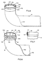
- intake pipe 18 generally is J-shaped, with the long section of the pipe 18, as indicated by the numeral 24, extending along the bottom of the water body and the shorter section, as indicated by the numeral 26 (Fig. 2), projecting upwardly a distance from the long section 24.
- the intake pipe opening 22 At the end of the shorter section 26 of pipe 18 and along its outermost perimeter 28 is the intake pipe opening 22.
- Intake pipe 18 is approximately 1.52 metres to 2.44 metres (8 to 15 feet) in diameter and approximately 15.24 cm (six inches) in thickness.
- the pipe is concrete and includes a metal plate in the interior thereof.
- Intake pipe screen 14 is generally funnel or cone shaped on its upper portion 30 and flattens out to a cylindrical shape on its lower portion 32, as shown in Fig. 3, with the lower portion 32 of the screen 14 being circumferentially parallel to intake pipe 18.
- screen 14 fits inside intake pipe 18 by inserting screen 14 into intake pipe opening 22. Since the design of screen 14 is such that the upper portion 30 flares outwardly, the screen 14 can extend into intake pipe 18 only to a certain point before its girth precludes screen 14 from extending any further into the intake pipe.
- the upper portion 30 of screen 24 extends beyond the perimeter of intake pipe 18 for a distance of approximately 0.61 metres to 2.44 metres (two to eight feet), such that as water flows into intake pipe opening 22, a greater amount of debris is filtered and precluded from entering into the intake pipe 18.
- Screen 14 is constructed from any conventional non-corrosive metal mesh on its upper portion 30.
- the lower portion 32 of screen 14 is preferably made of steel so that feed piping 13 can be attached thereto, as will be discussed in greater detail.
- the steel found in the lower portion 32 of screen 14 further enables screen 14 to be attached to intake pipe 18 by two bolts 34 that fit into bolt openings 36 (see Fig. 3).
- the bottom portion 38 of screen 14 includes a screened opening 40 that enables divers to pass into intake pipe 18.
- Screened opening 40 is made of the same mesh material as the rest of screen 14. Opening 40 includes hinge means 42 that allow it to open and close, and a locking mechanism 44 which maintains opening 40 in a closed position.
- flexible feed piping 12 extends the length of intake pipe 18, from pump house 20 to intake pipe opening 22, and connects to the flexible feed piping 13 mounted in the interior of intake pipe screen 14.
- feed piping 12 extends through the interior of the length of intake pipe 18 but then exits from intake pipe 18 through an opening 46 in pipe 18.
- opening 46 is located along the bottom of intake pipe 18, feed pipe 12 exits from opening 46 and extends around the side of intake pipe 18 to the top thereof.
- Feed pipe 12 extends along the top of intake pipe 18 to intake pipe opening 22 whereupon feed pipe 12 re-enters intake pipe 18 at opening 48 and connects to the feed pipe 13 mounted on the intake pipe screen 14.
- Feed pipe 12 is attached to the exterior of intake pipe 18 by a plurality of concrete anchor clamps 50.
- feed pipes 12 are connected by a juncture fitting 51 at their point of intersection.
- feed pipe 12 does not exit from opening 46 in intake pipe 18 but instead remains inside of pipe 18 and connects to feed pipe 13 in the interior and at the end of pipe section 26.
- feed pipe 13 is mounted on and attached to the interior of intake pipe screen 14. This procedure may be performed on land, where feed pipe 13 is welded to the lower portion 32 of screen 14 and may include non-corrosive clamps 52 for additional securement (Figs. 3, 4).
- a plurality of chemical dispensing valves 16 project inwardly from feed pipe 13, as shown in Figs. 1, 2 and 4, which spray and dispense the chemical solution that eliminates the zebra mussel larvae and adults. Valves 16 not only dispense the chemicals, but further serve as a connecting mechanism between each segment of flexible feed pipe 13.
- Another embodiment includes mounting flexible feed pipe 13 into the interior of intake pipe screen 14, the same as in the preferred embodiment.
- feed pipe 12 does not exit from opening 46 of intake pipe 18 but instead continues through the interior of intake pipe 18, as shown by broken lines in Fig. 2, and up through the shorter segment 26, where it connects to feed pipe 13 on the inside of intake pipe 18.
- Feed pipe 12 is connected to feed pipe 13 using the valve mechanism 54 described in the preferred embodiment.
- the valve mechanism 54 will not project outwardly from feed pipe 13 and pass through intake pipe 18, but instead will project inwardly without passing through intake pipe 18. All other aspects of this embodiment are the same as those described in the preferred embodiment.
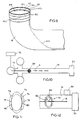
- Fig. 5 shows another embodiment in which the feed pipe 13 of the preferred embodiment is attached directly to the external surface of shorter section 26 of intake pipe 18 through the intake pipe opening 22.
- Fig. 5 illustrates feed pipe 112 extending through the inside length of intake pipe 18 and exiting therefrom at opening 146.
- Feed pipe 112 is attached to the exterior of intake pipe 18 by concrete anchor clamps 150 and extends up to feed pipe 113 which is circumferentially mounted to the exterior of intake pipe 18 by clamps 150.
- Feed pipe 112 is connected to feed pipe 113 by a juncture fitting 56.
- Chemical dispensing valves 116 connect the segments of feed pipe 113 and project through intake pipe 18 through a plurality of openings 58.
- the chemical solution is dispensed inside of intake pipe 18.
- Fig. 6 shows a further embodiment which involves mounting flexible feed pipe 13 of the preferred embodiment directly to the interior surface of shorter section 26 of intake pipe 18.
- feed pipe 212 extends through the inside length of intake pipe 18 until it reaches intake pipe opening 22. Thus, feed pipe 212 does not exit from intake pipe 18.
- Feed pipe 212 is connected to feed pipe 213, which is mounted to the interior of intake pipe 18 by an internal juncture fitting 156.
- Feed pipe 213 is mounted on the interior of intake pipe 18 by clamps 250 and includes chemical dispensing valves 216 facing radially inward.
- Figs. 7-9 illustrate additional embodiments wherein a U-shaped lip 60 completely covers the rim 62 of segment 26 of intake pipe 18, with the external side 64 of lip 60 being on the outside of intake pipe 18 and the internal side 66 of lip 60 being on the inside of intake pipe 18.
- feed pipe 312 is connected to feed pipe 313, the latter being mounted by clamps 350 to lip 60 on the external side 64.
- Chemical dispensing valves 316 connect the various segments of feed pipe 313, and radially project into the interior of intake pipe 18 through openings 158. Thus, the chemical solution is dispensed inside of intake pipe 18.
- feed pipe 412 is connected to feed pipe 413, the latter being mounted by clamps 450 to lip 60 on the internal side 66.
- Chemical dispensing valves 416 connect the segments of feed pipe 413 and dispense the chemical solution inside intake pipe 18 as previously described.
- the flexible feed piping 12, 112, 212, 312, 412 that extends through the interior of intake pipe 18 may be assembled therein by either of the following methods illustrated in Figs. 10-17.
- Fig. 10 illustrates the floatation ball technique which involves attaching floatation ball 68 to cable or rope 70.
- Cable or rope 70 is attached to barge 72.
- Ball 68, along with cable or rope 70, is caused to move in the direction of arrow A by water suction through intake pipe 18 and towards pump house 20.
- Ball 68 reaches pump house 20
- that portion of cable or rope 70 which is in pump house 20 is attached to feed pipe 12.
- Cable or rope 70 is then pulled back through intake pipe 18 towards intake pipe opening 22 by a rotating mechanism on barge 72.
- feed pipe 12 is also moved through intake pipe 18.
- Figs. 11-12 illustrate a technique that moves feed pipe 12 through intake pipe 18 by use of a pump propelled chasing device 74, such as a polypig device.
- Chasing device 74 generally includes a steel plate 76 that is surrounded by and attached to an inner tube 78 by bolts 80.
- Feed pipe 12 is connected to chasing device 74 by cables 82 or other connecting means.
- a pump 84 is attached to intake pipe 18 for pumping water from the pump house 20 towards the intake pipe opening 22. The water pressure generated by pump 84 moves chasing device 74 towards the intake pipe opening 22 and thereby pulls feed pipe 12 through intake pipe 18.
- Figs. 13-17 illustrate the cone-shaped apparatus technique for advancing the feed piping 12 through the intake pipe 18, which generally involves attaching cone-shaped apparatus 86 to cable or rope 88. Similar to the embodiment illustrated in Fig. 10, cable or rope 70 is attached to barge 72. Referring to Fig. 17, cone-shaped apparatus 86, along with cable or rope 88, is caused to move in the direction of arrow B by water suction through intake pipe 18 and towards pump house 20. When cone-shaped apparatus 86 reaches pump house 20, that portion of cable or rope 88 which is in pump house 20 is attached to feed piping 12. Cable or rope 70 is then pulled back through intake pipe 18 towards intake pipe opening 22 by a suitable rotating mechanism on barge 72. As cable or rope 88 is pulled through intake pipe 18, feed piping 12 is also moved through intake pipe 18.
- cone-shaped apparatus 86 comprises an outer cone element 90 that is attached to an inner cone element 92 at a small end 94 and a large end 96 of cone-shaped apparatus 86 by first and second ring-like structures 98 and 100, respectively.
- the outermost perimeter of first ring-like structure 98 is preferably welded or fused to outer cone 90
- the innermost perimeter of second ring-like structure 100 is preferably welded or fused to inner cone 92.
- An air pocket is created in the space 102 between outer cone 90 and inner cone 92, to provide cone-shaped apparatus 86 with additional buoyancy.
- Both small end 94 and large end 96 have open ends.
- a plurality of spokes extend across small end 94 and large end 96 of cone-shaped apparatus 86, as shown in Figs. 13 and 14.
- First spokes 104 extend across small end 94 and intersect at a centralized point 106.
- First spokes 104 also extend through inner cone 92 and outer cone 90 and thus serve to additionally secure the cones to each other.
- Second spokes 108 extend across large end 96 of cone-shaped apparatus 86 and intersect at a centralized point 110. Second spokes 108 also extend through inner cone 92 and outer cone 90 and therefore, secure cones 90, 92 at large end 96.
- a bar 112 extends downwardly from the center 106 of intersecting spokes 104 of small end 94 through the center 110 of intersecting spokes 108 of large end 96, and then further extend beyond large end 96 for a distance of approximately 0.305 metres to 0.61 metres (one to two feet).
- a swivel hook 114 is located on the bottom extended portion of bar 112. Swivel hook 114 may be attached to cable or rope 88.
- Figs. 14 and 15 show plate 116 which extends circumferentially around one-half of the exterior of outer cone 90 which is located nearest to large end 96.
- Plate 116 is approximately 7.62 cm to 15.24 cm (three to six inches) in width and 6.35 mm to 2.54 cm (1/4 to one inch) in thickness.
- Plate 116 is attached to the exterior of large cone 90 by a plurality of bolts 118 which extend through both large cone 90 and small cone 92.
- Plate 116 is adapted to hold magnetic weights 120 to allow for weight adjustment of cone-shaped apparatus 86.
- Fig. 16 shows another embodiment of cone-shaped apparatus 86.
- This embodiment includes a closed end 122 in outer cone 90. All other aspects of this embodiment, aside from the closed end 122, are the same as the embodiment shown in Figs. 13-15 and 17.
- An inner tube 124 may be placed around the small end 94 of outer cone 90, if necessary, to maintain the floatation of small end 94 in a horizontal plane.
- Fig. 17 demonstrates the manner in which cone-shaped apparatus 86 is positioned in intake pipe 18.
- small end 94 of apparatus 86 faces towards pump house 20 and the large end 96 faces towards the intake pipe opening.
- cable or rope 88 is attached to apparatus 86 by swivel hook 114 of bar 112.
- Apparatus 86 is moved through intake pipe 18 in the direction of arrow B in the manner previously explained.
- Apparatus 86 is generally made of a material that is buoyant, such as plastic or fiberglass.
- the size of apparatus 86 is variable and depends on the size of the intake pipe which it moves through.
- the embodiments shown in Figs. 1-9 operate by adding a chemical solution to feed pipe 12 at that portion of feed pipe 12 located in pump house 20.
- the solution travels through the intake pipe 18 via feed pipe 12 to each intake pipe opening 22 through junction fitting 51.
- the solution in feed pipe 12 flows, through juncture fittings 48, into each feed pipe 13 which is mounted on intake pipe screen 14, or directly on the exterior or interior of intake pipe 18 in accordance with the teachings of the preferred embodiments.
- the solution then flows through feed pipe 13 and is dispensed in an inwardly radial direction out of dispensing valves 16 into intake pipe 18.
- the solution may be dispensed as frequently as desired. When the solution contacts the mussels, it destroys them.
- the materials from which the feed pipes of the apparatus are constructed include any material which is compatible with the chemical solution being dispensed.
- the valves and juncture fitting should be made from non-corrosive materials.
- the intake pipe is usually made from steel and concrete.
- the intake pipe screen is also made from any non-corrosive metal mesh on its upper portion and any non-corrosive metal on its lower portion.
- shut-off valves may be installed in the long section of the intake pipe. A diver will then be able to enter the intake pipe, shut off the valves and apply hydrostatic pressure to the pipe to determine if the feed piping is leaking or if any feed piping lines are blown out.
- the above apparatus has been described in terms of approximate measurements of the various components, as it should be understood that the size of the feed pipes 12, 13, screen 14 and intake pipe 18, may vary according to need. Thus, there may be a plurality of sizes of the above components. The sizes can vary, but are limited to the manufacturing equipment's capabilities.
Landscapes
- Engineering & Computer Science (AREA)
- Chemical & Material Sciences (AREA)
- General Engineering & Computer Science (AREA)
- Life Sciences & Earth Sciences (AREA)
- Health & Medical Sciences (AREA)
- Medicinal Chemistry (AREA)
- Mechanical Engineering (AREA)
- Hydrology & Water Resources (AREA)
- Environmental & Geological Engineering (AREA)
- Water Supply & Treatment (AREA)
- Organic Chemistry (AREA)
- Catching Or Destruction (AREA)
- Feeding, Discharge, Calcimining, Fusing, And Gas-Generation Devices (AREA)
- Investigating Or Analyzing Materials By The Use Of Ultrasonic Waves (AREA)
- Pipeline Systems (AREA)
Claims (9)
- Système comprenant une conduite d'adduction submergée (18) et un appareil (10) pour distribuer des produits chimiques à la conduite d'adduction (18), l'appareil comprenant une première conduite d'alimentation (12) et une seconde conduite d'alimentation (13), les conduites d'alimentation étant montées sur la conduite d'adduction (18), la première conduite d'alimentation (12) s'étendant le long et sur la longueur de la conduite d'adduction (18) et étant connectée à la deuxième conduite d'alimentation (13), la deuxième conduite d'alimentation (13) étant montée sur la conduite d'adduction (18) sur la partie de la conduite d'adduction (18) la plus proche possible de la bouche (22) de la conduite d'adduction et la deuxième conduite d'alimentation (13) comprenant une pluralité de vannes de distribution s'étendant vers l'intérieur (16) pour distribuer des produits chimiques dans la conduite d'adduction (18), les produits chimiques étant pendant le fonctionnement du système délivrés à la deuxième conduite d'alimentation (13) à travers la première conduite d'alimentation (12).
- Système selon la revendication 1, dans lequel une grille à tamis (14) est montée sur la conduite d'adduction (18) et recouvre la bouche (22) de la conduite d'adduction.
- Système selon la revendication 1, dans lequel la deuxième conduite d'alimentation (113) est fixée à l'extérieur de la conduite d'adduction (18).
- Système selon la revendication 1, dans lequel la deuxième conduite d'alimentation (213) est fixée à l'intérieur de la conduite d'adduction (18).
- Système selon la revendication 1, dans lequel la deuxième conduite d'alimentation (313) est montée sur la conduite d'adduction (18) en fixant la deuxième conduite d'alimentation (313) à un élément en U faisant lèvre (60), l'élément en U faisant lèvre (60) recouvrant de façon circonférentielle le rebord (62) de la bouche (22) de la conduite d'adduction.
- Système selon la revendication 5, dans lequel la deuxième conduite d'alimentation (313) est fixée au côté extérieur de l'élément faisant lèvre (60) et où la pluralité de vannes de distribution (316) fait saillie depuis le côté intérieur de l'élément faisant lèvre (60).
- Système selon la revendication 5, dans lequel la deuxième conduite d'alimentation (413) est fixée au côté intérieur de l'élément faisant lèvre (60) et où la pluralité de vannes de distribution (416) fait saillie depuis le côté intérieur de l'élément faisant lèvre (60).
- Système comprenant une conduite d'adduction submergée (18) et un appareil (10) pour distribuer des produits chimiques à la conduite d'adduction (18), l'appareil comprenant une première conduite d'alimentation (12), une deuxième conduite d'alimentation (13) et une structure (14) de grille à tamis sur la conduite d'adduction, la première conduite d'alimentation (12) s'étendant le long et sur la longueur de la conduite d'adduction (18), la première conduite d'alimentation (12) étant connectée à la deuxième conduite d'alimentation (13), la deuxième conduite d'alimentation (13) étant montée sur la structure (14) de grille à tamis de la conduite d'adduction, la structure (14) de grille à tamis de la conduite d'adduction étant fixée à la bouche (22) de la conduite d'adduction (18) et la deuxième conduite d'alimentation (13) comprenant une pluralité de vannes de distribution (16) pour distribuer des produits chimiques dans la conduite d'adduction (18), les produits chimiques étant pendant le fonctionnement du système délivrés à la deuxième conduite d'alimentation à travers la première conduite d'alimentation.
- Méthode pour distribuer des produits chimiques dans un liquide en écoulement passant dans une conduite d'adduction submergée (18) comprenant une première et une deuxième conduites (12,13) d'alimentation en produits chimiques interconnectées, situées sur la conduite d'adduction et à la bouche d'adduction (22) de la conduite submergée, la deuxième conduite d'alimentation présentant une pluralité de vannes de distribution (16) qui libèrent une solution chimique directement dans le liquide en écoulement passant dans la conduite d'adduction, la méthode comprenant les étapes consistant à : faire passer la solution chimique dans la première conduite d'alimentation, faire passer la solution chimique à travers la première conduite d'alimentation et dans la deuxième conduite d'alimentation, libérer la solution chimique à travers la pluralité de vannes de distribution directement dans la bouche d'adduction pour mélanger la solution chimique au liquide en écoulement passant dans la conduite d'adduction, sans surveillance et en quantité suffisante pour distribuer les produits chimiques sur les organismes présents à l'intérieur de la conduite d'adduction.
Applications Claiming Priority (5)
| Application Number | Priority Date | Filing Date | Title |
|---|---|---|---|
| US46495890A | 1990-01-16 | 1990-01-16 | |
| US464958 | 1990-01-16 | ||
| US479337 | 1990-02-13 | ||
| US07/479,337 US5008075A (en) | 1990-01-16 | 1990-02-13 | Preventative maintenance system for underwater pipes |
| PCT/US1991/000330 WO1991010516A1 (fr) | 1990-01-16 | 1991-01-16 | Systeme preventif d'entretien de canalisations submergees |
Publications (3)
| Publication Number | Publication Date |
|---|---|
| EP0510077A1 EP0510077A1 (fr) | 1992-10-28 |
| EP0510077A4 EP0510077A4 (en) | 1993-03-31 |
| EP0510077B1 true EP0510077B1 (fr) | 1996-11-27 |
Family
ID=27041154
Family Applications (1)
| Application Number | Title | Priority Date | Filing Date |
|---|---|---|---|
| EP91903002A Expired - Lifetime EP0510077B1 (fr) | 1990-01-16 | 1991-01-16 | Systeme preventif d'entretien de canalisations submergees |
Country Status (6)
| Country | Link |
|---|---|
| US (2) | US5008075A (fr) |
| EP (1) | EP0510077B1 (fr) |
| AT (1) | ATE145569T1 (fr) |
| CA (1) | CA2018617C (fr) |
| DE (1) | DE69123347D1 (fr) |
| WO (1) | WO1991010516A1 (fr) |
Families Citing this family (19)
| Publication number | Priority date | Publication date | Assignee | Title |
|---|---|---|---|---|
| US5128050A (en) * | 1991-05-06 | 1992-07-07 | Calgon Corporation | Method for controlling zebra mussels in ship ballast tanks |
| US5192451A (en) * | 1991-05-06 | 1993-03-09 | Calgon Corporation | Method for controlling zebra mussels in ship ballast tanks |
| US5143623A (en) * | 1991-06-17 | 1992-09-01 | Kroll Brian L | Nutrient and particle removal: method and apparatus for treatment of existing lakes, ponds and water bodies |
| US5256310A (en) * | 1992-03-31 | 1993-10-26 | Exxon Chemical Patents Inc. | Treatment of fresh water for zebra mussel infestation |
| US5376282A (en) * | 1993-06-18 | 1994-12-27 | Ohio University | Method and apparatus for controlling zebra mussels in water conduits |
| US5989323A (en) * | 1993-12-09 | 1999-11-23 | The Research Foundation Of State University Of New York | Aquatic antifouling compositions and methods |
| CA2178500C (fr) * | 1993-12-09 | 2004-07-13 | Gordon T. Taylor | Procedes et peintures anti fouling marines |
| US5520821A (en) * | 1995-05-04 | 1996-05-28 | Screptock; Andrew D. | Apparatus for preventing or eliminating zebra mussel infestation of a domestic water supply |
| GB2303316B (en) | 1995-07-19 | 1999-06-16 | Baker Hughes Ltd | Biofouling reduction |
| AU738740B2 (en) * | 1995-07-19 | 2001-09-27 | Baker Hughes Limited | Biofouling reduction |
| US5723044A (en) * | 1995-07-31 | 1998-03-03 | Zebra Mussel Filter Systems, Inc. | Water filtration system for control of the zebra mussel |
| US5525222A (en) * | 1995-07-31 | 1996-06-11 | Zebra Mussel Filter Systems, Inc. | Water filtration system for control of the zebra mussel |
| US5979478A (en) * | 1997-05-05 | 1999-11-09 | Screptock; Andrew D. | Apparatus and method for treating water in a water supply system |
| US5948279A (en) * | 1997-09-25 | 1999-09-07 | Ohio University | Method and apparatus for controlling macrofoulers in on-demand water conduits |
| US6165372A (en) | 1999-08-11 | 2000-12-26 | Betzdearborn Inc. | Injection quill for water treatment |
| US8799042B2 (en) | 2011-08-08 | 2014-08-05 | International Business Machines Corporation | Distribution network maintenance planning |
| US20130037492A1 (en) * | 2011-08-09 | 2013-02-14 | Severn Trent De Nora, Llc | System and Method for Optimizing the Mixing of Hypochlorite with Ballast Water |
| AU2014223283B2 (en) * | 2013-02-28 | 2018-11-01 | Pure Technologies Ltd. | Drogue for confined spaces |
| CN118167658B (zh) * | 2024-05-14 | 2024-10-08 | 鱼波 | 一种用于农田灌溉的抽水装置 |
Family Cites Families (37)
| Publication number | Priority date | Publication date | Assignee | Title |
|---|---|---|---|---|
| US333204A (en) * | 1885-12-29 | Apparatus for steaming piles | ||
| US920455A (en) * | 1906-12-14 | 1909-05-04 | Nat Water Main Cleaning Company | Device for passing cables through pipe-lines. |
| US1033587A (en) * | 1910-04-15 | 1912-07-23 | Nat Water Main Cleaning Company | Device for passing cables through pipe-lines. |
| US1445839A (en) * | 1921-11-30 | 1923-02-20 | Mahoney Timothy Joseph | Art of navigation |
| US1620788A (en) * | 1925-12-10 | 1927-03-15 | John M Thompson | Device for passing cables through pipe lines |
| US1890712A (en) * | 1929-10-07 | 1932-12-13 | Arthur H Zeitz | Apparatus for clarifying liquids |
| US2138831A (en) * | 1937-01-29 | 1938-12-06 | Frederick G Brammer | Means and method for protection from marine parasites |
| US3120491A (en) * | 1960-09-08 | 1964-02-04 | Themas C Kincaid | Water filter for farm pond |
| US3441439A (en) * | 1964-12-11 | 1969-04-29 | Distillers Co Yeast Ltd | Apparatus and method for reducing fouling of underwater surfaces |
| DE1609175A1 (de) * | 1965-06-02 | 1970-02-12 | Woma Appbau W Maasberg & Co Gm | Vorrichtung zur Reinigung von Abwasserkanaelen |
| US3321184A (en) * | 1966-01-03 | 1967-05-23 | John B Goss | Self-propelling hose-nozzle assembly and method of using same |
| US3398831A (en) * | 1966-01-20 | 1968-08-27 | Adrian L. Jones | Filter structure |
| GB1298241A (en) * | 1970-01-01 | 1972-11-29 | Gen Descaling Co Ltd | An improved bi-directional pipeline pig |
| SE395591B (sv) * | 1970-12-25 | 1977-08-22 | Kumiai Chemical Industry Co | Anvendning av vissa difenyletrar for att bekempa havsorganismer och for att forhindra vidheftning av havsorganismer till havsvattenror och andra foremal i havsvatten |
| JPS5226830B2 (fr) * | 1973-10-12 | 1977-07-16 | ||
| US4182497A (en) * | 1978-01-09 | 1980-01-08 | Brito Manuel J | Gutter cleaning device |
| US4333833A (en) * | 1978-05-08 | 1982-06-08 | Fischer & Porter Co. | In-line disinfectant contactor |
| US4269264A (en) * | 1978-07-03 | 1981-05-26 | Water Services Of America, Inc. | Cleaning of heat exchanger tubing |
| DE7822037U1 (de) * | 1978-07-22 | 1978-11-23 | Woma-Apparatebau Wolfgang Maasberg & Co Gmbh, 4100 Duisburg | Rueckstossbetriebene spritzduese |
| US4216910A (en) * | 1978-12-07 | 1980-08-12 | Kimbrough Wade L | 360 Degree internal spray cleaning |
| US4259269A (en) * | 1979-10-19 | 1981-03-31 | Nalco Chemical Company | Chemical feed system |
| US4310423A (en) * | 1979-12-26 | 1982-01-12 | Brown Steven F | Stream water pumping means and method |
| DE3011932C2 (de) * | 1980-03-27 | 1986-02-13 | Mitsubishi Gas Chemical Co., Inc., Tokio/Tokyo | Verfahren zum Verhindern des Wachstums von Schalentieren, Bryozoen und/oder Hydrozoen auf einer Oberfläche |
| US4313827A (en) * | 1980-09-04 | 1982-02-02 | Fischer & Porter Co. | Enhanced disinfection system |
| US4328638A (en) * | 1980-09-19 | 1982-05-11 | Illinois Power Company | Method of eliminating mussels and the like from an underwater bed |
| FR2521446B1 (fr) * | 1982-02-15 | 1987-06-05 | Beaudrey & Cie | Filtre a crepine fixe en particulier pour eaux industrielles |
| US4498659A (en) * | 1982-03-02 | 1985-02-12 | Brockelsby Iii Pete | Conical line-pulling carrier |
| US4498932A (en) * | 1983-12-14 | 1985-02-12 | Shell Oil Company | Pipeline pig with restricted fluid bypass |
| US4556486A (en) * | 1984-02-15 | 1985-12-03 | Lesley Merket | Circulating water filtering system and method of operation |
| DE3412319C1 (de) * | 1984-04-03 | 1985-06-27 | Woma-Apparatebau Wolfgang Maasberg & Co Gmbh, 4100 Duisburg | Als hydraulische Wirbelstrahlduese ausgebildetes Arbeitswerkzeug |
| US4582610A (en) * | 1985-09-03 | 1986-04-15 | Martin Baker | Well water aeration system |
| US4699163A (en) * | 1985-12-16 | 1987-10-13 | Baziuk Slawko M | Head for cleaning the interior of a pipe |
| GB2189712B (en) * | 1986-05-02 | 1989-11-29 | Biwater Treatment Ltd | Water filtration installations |
| US4857209A (en) * | 1986-07-23 | 1989-08-15 | Betz Laboratories, Inc. | Method for controlling macroinvertebrates |
| EP0264767B1 (fr) * | 1986-10-15 | 1992-07-15 | Rudolf Harmstorf | Procédé et dispositif pour insérer un élément sous forme de corde dans un conduit de câble |
| US4818413A (en) * | 1987-08-05 | 1989-04-04 | Nalco Chemical Company | Biocide water treatment having reduced copper corrosion |
| US4887931A (en) * | 1989-02-16 | 1989-12-19 | Baker Hughes Incorporated | Method and apparatus for towing subsea pipeline sections |
-
1990
- 1990-02-13 US US07/479,337 patent/US5008075A/en not_active Expired - Lifetime
- 1990-06-08 CA CA002018617A patent/CA2018617C/fr not_active Expired - Lifetime
-
1991
- 1991-01-16 WO PCT/US1991/000330 patent/WO1991010516A1/fr not_active Ceased
- 1991-01-16 DE DE69123347T patent/DE69123347D1/de not_active Expired - Lifetime
- 1991-01-16 EP EP91903002A patent/EP0510077B1/fr not_active Expired - Lifetime
- 1991-01-16 AT AT91903002T patent/ATE145569T1/de not_active IP Right Cessation
- 1991-03-15 US US07/669,774 patent/US5308193A/en not_active Expired - Lifetime
Also Published As
| Publication number | Publication date |
|---|---|
| CA2018617A1 (fr) | 1991-07-16 |
| ATE145569T1 (de) | 1996-12-15 |
| US5008075A (en) | 1991-04-16 |
| DE69123347D1 (de) | 1997-01-09 |
| US5308193A (en) | 1994-05-03 |
| EP0510077A1 (fr) | 1992-10-28 |
| EP0510077A4 (en) | 1993-03-31 |
| WO1991010516A1 (fr) | 1991-07-25 |
| CA2018617C (fr) | 1992-11-03 |
Similar Documents
| Publication | Publication Date | Title |
|---|---|---|
| EP0510077B1 (fr) | Systeme preventif d'entretien de canalisations submergees | |
| US6221257B1 (en) | Apparatus and method for treatment of discharged water and other fluids | |
| US4350589A (en) | Floating jet aerator | |
| EP1450922B1 (fr) | Doseur de reactif, systeme et procede | |
| US7468082B2 (en) | Self cleaning gas filtering system and method | |
| US9068338B2 (en) | Lift station flow diverter and method of using same | |
| US6458282B1 (en) | Method and apparatus for separating floating pollutants | |
| US8870445B2 (en) | Liquid accelerator and chemical mixing apparatus and method | |
| US20050199551A1 (en) | Method and system for filtering sediment-bearing fluids | |
| US20070267359A1 (en) | Aeration method of pool water and apparatus there of | |
| US8740194B1 (en) | Buoyant aerator array with remote air supply | |
| LePage | The impact of Dreissena polymorpha on waterworks operations at Monroe, Michigan: a case history | |
| CN114902983B (zh) | 鲍鱼养殖设备和方法 | |
| GB2242140A (en) | Tank for fish farming | |
| US8216456B2 (en) | Water treatment apparatus adaptible to natural water environment | |
| US20040200766A1 (en) | Porous dike intake structure for fish diversion | |
| US8622371B1 (en) | Anchored aerator | |
| US8678358B1 (en) | Buoyant aerator with support legs | |
| US8622370B1 (en) | Aerator air distribution manifold | |
| GB2246981A (en) | Oil spill barrier of air bubbles; Tubes | |
| FR3041342A1 (fr) | Dispositif de traitement des eaux et embarcation comportant un tel dispositif | |
| EP0802888A1 (fr) | Systeme et procede d'aeration | |
| RU212776U1 (ru) | Секция бонового заграждения | |
| EP0012727B1 (fr) | Barrage flottant anti-pollution comprenant des éléments flottants principaux employés comme réceptacles pour recueillir, transporter et lancer des sections de barrage | |
| KR100595770B1 (ko) | 수중 분말 방출장치 |
Legal Events
| Date | Code | Title | Description |
|---|---|---|---|
| PUAI | Public reference made under article 153(3) epc to a published international application that has entered the european phase |
Free format text: ORIGINAL CODE: 0009012 |
|
| 17P | Request for examination filed |
Effective date: 19920811 |
|
| AK | Designated contracting states |
Kind code of ref document: A1 Designated state(s): AT BE CH DE DK ES FR GB GR IT LI LU NL SE |
|
| A4 | Supplementary search report drawn up and despatched |
Effective date: 19930205 |
|
| AK | Designated contracting states |
Kind code of ref document: A4 Designated state(s): AT BE CH DE DK ES FR GB GR IT LI LU NL SE |
|
| 17Q | First examination report despatched |
Effective date: 19940921 |
|
| GRAH | Despatch of communication of intention to grant a patent |
Free format text: ORIGINAL CODE: EPIDOS IGRA |
|
| GRAH | Despatch of communication of intention to grant a patent |
Free format text: ORIGINAL CODE: EPIDOS IGRA |
|
| GRAH | Despatch of communication of intention to grant a patent |
Free format text: ORIGINAL CODE: EPIDOS IGRA |
|
| GRAA | (expected) grant |
Free format text: ORIGINAL CODE: 0009210 |
|
| AK | Designated contracting states |
Kind code of ref document: B1 Designated state(s): AT BE CH DE DK ES FR GB GR IT LI LU NL SE |
|
| PG25 | Lapsed in a contracting state [announced via postgrant information from national office to epo] |
Ref country code: IT Free format text: LAPSE BECAUSE OF FAILURE TO SUBMIT A TRANSLATION OF THE DESCRIPTION OR TO PAY THE FEE WITHIN THE PRE;WARNING: LAPSES OF ITALIAN PATENTS WITH EFFECTIVE DATE BEFORE 2007 MAY HAVE OCCURRED AT ANY TIME BEFORE 2007. THE CORRECT EFFECTIVE DATE MAY BE DIFFERENT FROM THE ONE RECORDED.SCRIBED TIME-LIMIT Effective date: 19961127 Ref country code: AT Effective date: 19961127 Ref country code: CH Free format text: LAPSE BECAUSE OF FAILURE TO SUBMIT A TRANSLATION OF THE DESCRIPTION OR TO PAY THE FEE WITHIN THE PRESCRIBED TIME-LIMIT Effective date: 19961127 Ref country code: BE Effective date: 19961127 Ref country code: DK Effective date: 19961127 Ref country code: ES Free format text: THE PATENT HAS BEEN ANNULLED BY A DECISION OF A NATIONAL AUTHORITY Effective date: 19961127 Ref country code: NL Free format text: LAPSE BECAUSE OF FAILURE TO SUBMIT A TRANSLATION OF THE DESCRIPTION OR TO PAY THE FEE WITHIN THE PRESCRIBED TIME-LIMIT Effective date: 19961127 Ref country code: LI Free format text: LAPSE BECAUSE OF FAILURE TO SUBMIT A TRANSLATION OF THE DESCRIPTION OR TO PAY THE FEE WITHIN THE PRESCRIBED TIME-LIMIT Effective date: 19961127 Ref country code: FR Effective date: 19961127 Ref country code: GR Free format text: LAPSE BECAUSE OF FAILURE TO SUBMIT A TRANSLATION OF THE DESCRIPTION OR TO PAY THE FEE WITHIN THE PRESCRIBED TIME-LIMIT Effective date: 19961127 |
|
| REF | Corresponds to: |
Ref document number: 145569 Country of ref document: AT Date of ref document: 19961215 Kind code of ref document: T |
|
| REF | Corresponds to: |
Ref document number: 69123347 Country of ref document: DE Date of ref document: 19970109 |
|
| PG25 | Lapsed in a contracting state [announced via postgrant information from national office to epo] |
Ref country code: LU Free format text: LAPSE BECAUSE OF NON-PAYMENT OF DUE FEES Effective date: 19970131 |
|
| PG25 | Lapsed in a contracting state [announced via postgrant information from national office to epo] |
Ref country code: SE Effective date: 19970227 |
|
| PG25 | Lapsed in a contracting state [announced via postgrant information from national office to epo] |
Ref country code: DE Effective date: 19970228 |
|
| EN | Fr: translation not filed | ||
| NLV1 | Nl: lapsed or annulled due to failure to fulfill the requirements of art. 29p and 29m of the patents act | ||
| REG | Reference to a national code |
Ref country code: CH Ref legal event code: PL |
|
| PLBE | No opposition filed within time limit |
Free format text: ORIGINAL CODE: 0009261 |
|
| STAA | Information on the status of an ep patent application or granted ep patent |
Free format text: STATUS: NO OPPOSITION FILED WITHIN TIME LIMIT |
|
| 26N | No opposition filed | ||
| REG | Reference to a national code |
Ref country code: GB Ref legal event code: IF02 |
|
| PGFP | Annual fee paid to national office [announced via postgrant information from national office to epo] |
Ref country code: GB Payment date: 20051214 Year of fee payment: 16 |
|
| GBPC | Gb: european patent ceased through non-payment of renewal fee |
Effective date: 20070116 |
|
| PG25 | Lapsed in a contracting state [announced via postgrant information from national office to epo] |
Ref country code: GB Free format text: LAPSE BECAUSE OF NON-PAYMENT OF DUE FEES Effective date: 20070116 |