EP0510176B1 - Ensemble chargeur destine a refaire de maniere selective l'empilage a la fois des originaux individuels et des originaux a pliage paravent provenant d'une machine de reproduction de documents - Google Patents
Ensemble chargeur destine a refaire de maniere selective l'empilage a la fois des originaux individuels et des originaux a pliage paravent provenant d'une machine de reproduction de documents Download PDFInfo
- Publication number
- EP0510176B1 EP0510176B1 EP92900961A EP92900961A EP0510176B1 EP 0510176 B1 EP0510176 B1 EP 0510176B1 EP 92900961 A EP92900961 A EP 92900961A EP 92900961 A EP92900961 A EP 92900961A EP 0510176 B1 EP0510176 B1 EP 0510176B1
- Authority
- EP
- European Patent Office
- Prior art keywords
- restacking
- originals
- tray
- fan
- folded
- Prior art date
- Legal status (The legal status is an assumption and is not a legal conclusion. Google has not performed a legal analysis and makes no representation as to the accuracy of the status listed.)
- Expired - Lifetime
Links
- 230000001154 acute effect Effects 0.000 claims description 2
- 230000001133 acceleration Effects 0.000 claims 1
- 238000013016 damping Methods 0.000 claims 1
- 230000007246 mechanism Effects 0.000 description 6
- 230000002411 adverse Effects 0.000 description 2
- 230000004075 alteration Effects 0.000 description 1
- 230000008859 change Effects 0.000 description 1
- 238000010276 construction Methods 0.000 description 1
- 230000009977 dual effect Effects 0.000 description 1
- 238000009420 retrofitting Methods 0.000 description 1
Images



Classifications
-
- B—PERFORMING OPERATIONS; TRANSPORTING
- B65—CONVEYING; PACKING; STORING; HANDLING THIN OR FILAMENTARY MATERIAL
- B65H—HANDLING THIN OR FILAMENTARY MATERIAL, e.g. SHEETS, WEBS, CABLES
- B65H45/00—Folding thin material
- B65H45/02—Folding limp material without application of pressure to define or form crease lines
- B65H45/06—Folding webs
- B65H45/10—Folding webs transversely
- B65H45/101—Folding webs transversely in combination with laying, i.e. forming a zig-zag pile
- B65H45/1015—Folding webs provided with predefined fold lines; Refolding prefolded webs, e.g. fanfolded continuous forms
Definitions
- the instant invention relates to a document restacking hopper assembly for selectively restacking both individual original documents and fan-folded original documents after the documents have been reproduced by a document reproduction machine.
- US-A-4,068,946 discloses a reproducing machine in which the capability of refolding fan-folded originals is built into the machine in such a way as to require alteration of other components of the machine, rather than being integrated in such a way as to not interfere with other components.
- US-A-4,087,172 is directed to the broad concept of retrofitting a commercial photocopying machine to handle fan-folded originals as well as individual originals; however, the same hopper which collects fan-folded originals is not used to collect individual originals.
- the hopper which is retrofitted to the reproducing machine has the characteristics of an "add-on", rather than the characteristics of an integral component.
- US-A-4,754,960 discloses an apparatus for restacking both individual originals and fan-folded originals, said apparatus having a tray having a first portion for restacking individual originals and a second portion for restacking fan-folded originals.
- the instant invention provides a new and improved hopper for selectively restacking both individual originals and fan-folded originals from a document reproducing machine. According to the present invention, there is provided an apparatus for restacking both individual originals and fan-folded originals as defined in claim 1.
- the apparatus for restacking both individual originals and fan-folded originals comprises a unitary tray having a first portion defining a first substantially planar surface for restacking individual originals, and a second portion defining a second substantially planar surface for restacking fan-folded originals, said second portion integral with said first portion and said first surface intersecting said second surface at a fixed angle, and means for mounting the tray with respect to the reproducing machine for movement between a first mode, wherein the tray is positioned to enable individual originals to be restacked in the first portion thereof, and a second mode, wherein the tray is positioned to enable fan-folded originals to be restacked in the second portion thereof.
- the tray is pivotally mounted with respect to the reproducing machine.
- the tray has a first end and a second end with a first portion for restacking individual originals being disposed at the first end and a second portion for restacking fan-folded originals being disposed between the first and second ends.
- the tray is pivotally mounted with respect to the reproducing machine; whereby the tray is in the first mode for restacking individual originals when the first end is pivoted toward the reproducing machine, and is in a second mode for restacking fan-folded originals when the first end is pivoted away from the reproducing machine so as to expose the second portion of the tray.
- the instant invention further contemplates a combination, which combination includes a reproducing machine for copying both individual originals and fan-folded originals and a restacking hopper assembly for restacking the originals after copying.
- the restacking hopper assembly includes a base securable to the reproducing machine at a location on the reproducing machine where copied originals emerge from the reproducing machine.
- a tray having first and second ends is pivoted at its second end to the base adjacent the lower end of the base. The tray pivots between a first mode for restacking individual originals in the tray and a second mode for restacking fan-folded originals in the tray.
- the restacking hopper assembly includes thereon devices for facilitating restacking of both individual and fan-folded originals.
- the tray receives individual originals proximate the first end thereof and receives fan-folded originals at a location between the first and second ends.
- restacking of fan-folded originals is facilitted by a tractor assembly disposed in the base between the lower and upper ends thereof, with the tractor assembly being exposed for use upon pivoting the trya from the first mode, for restacking individual originals, to the second mode, for restacking fan-folded originals.
- the base includes a slated surface adjacent to the upper end thereof. Restacking of individual originals is facilitated by at least one flexible member overlying the slated surface for retaining individual sheets between the slanted surface and the flexible member.
- the flexible member is mounted on a horizontal rod which is connected by a linkage to a vertical rod engageable by the tray as the tray pivots from the second mode to the first mode.
- the vertical rod moves the horizontal rod to shift the flexible member from an operative to an inoperative position.
- Fan-folded originals 14 are most often computer generated printouts. When making copies of computer generated printouts, it is necessary to unfold the fan-fold stack to reproduce images thereof, and thereafter it is highly desirable to restack the individual connected sheets in the original fan-folded configuration. Individual originals 12 are transported, for example, by an original positioner 16 mounted on top of the reproducing machine 10 and are restacked in the same order as copied, while fan-folded originals 14 are pulled from a basket 17 at the opposite end of the reproducing machine.
- a restacking hopper assembly designated generally by the numeral 18, configured in accordance with the principles of the instant invention.
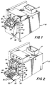
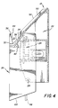
- the restacking hopper 18 assumes a first mode, shown in Figure 1, for restacking individual originals 12 and a second mode, shown in Figures 2 and 3, for restacking fan-folded originals 14.
- the restacking hopper assembly 18 is attached to a side panel 20 of the reproducing machine 10 and includes a vertically oriented base, designated generally by the numeral 22; a tractor feed, designated generally by the number 24, mounted within the base; and a tray, designated generally by the numeral 26, secured by pivot pins 28 and 30 to the base.
- Tray 26 is in a first mode for restacking individual originals 12 in Figure 1, and in Figures 2 and 3, has pivoted on pivot pins 28 and 30 to a second mode for restacking fan-folded originals 14.
- a first end 32 of the tray 26, includes a groove 33 defined by first and second sets of spaced apart, aligned flanges 34 and 36 while a second end 37 of the tray 26 is secured to the base 22 by the pivot pins 28 and 30.
- each of the flanges 34 is a flat plate having a first flat surface 38 facing inwardly to define a plane forming one side of the groove 33 and a second flat surface 42 which faces the vertical base 18.
- the plane defined by the flat surfaces 38 extends parallel with respect to the axis 28-30 about which the tray 26 pivots and is at an oblique angle to the vertical when the tray 26 is in the first mode of Figure 1.
- the second flanges 36 are triangular plates having edges 44, which edges face the surfaces 38 at an acute angle to form the second side of the groove 33.
- the plates 36 have spaces 46 ( Figures 1-3) therebetween, while the plates 34 have spaces 48 therebetween with the spaces 46 being aligned with plates 34 and the spaces 48 being aligned with plates 36.
- the hopper assembly 18 when the tray 26 is in its vertical orientation, the hopper assembly 18 is in the first mode for restacking individual originals 12, wherein the flanges 34 are oriented at an angle with respect to the base 22 and slant in the same direction as a paper slide surface 50 on the base.
- the paper slide surface 50 has a plurality of ribs 52 over which the individual originals 12 slide after being copied and ejected from the positioner 16.
- a pair of spaced danglers 54 and 56 are pivoted on a rod 58 which holds the attached ends of each dangler in spaced relation with respect to the paper slide surface 50.
- the free ends of the danglers 54 and 56 respectively, rest on two of the flanges 34 at the upper or first end 32 of the tray 26 so as to form a converging guide which retains first and subsequent individual originals 12 in a space 67 between the danglers and paper slide 50 to keep the individual originals from falling out of the groove 33.
- the danglers 54 and 56 have an operative mode ( Figures 1 and 6) and a retracted mode ( Figures 2, 3 and 7).
- the tray 26 is pivoted about pivots 28 and 30 away from the vertically oriented base 22 and extends approximately 90° with respect thereto.
- the tray 26 provides a second original document restacking portion, defined by a horizontal support surface 60 created by a grid of cross ribs 61, upon which the fan-folded original 14 is refolded after copying by the machine 10.
- retaining arms 64 and 66 on the tractor mechanism 24 are pivoted outwardly (see Figure 2) so as to receive one panel of the fan-folded original 14 therebetween.
- the retaining arms 64 and 66 are then pivoted back over the original 14 (see Figure 3) to hold the original in engagement with sprockets 69 and 70 (see Figure 2) of the tractor assembly 24.
- the tractor assembly 24, including its drive motor M is of conventional construction and other than nesting in the vertical base 22 so as to cooperatively function with the hopper assembly 18, the tractor assembly functions in a conventional manner to pull and guide the fan-folded original 14 after it has been copied.
- the tray 26 When the tray 26 is pivoted to the second mode illustrated in Figures 2, 3 and 5, the tray operates a dangler retraction mechanism, designated generally by numeral 71 ( Figures 6 and 7) which causes the rod 58, holding the danglers 54 and 56, to retract to a non-operative mode where the danglers rest against the surface 50 between pairs of ribs 52.
- the fan-folded original 14 then passes over the danglers 54 and 56 as it emerges from the reproducing machine 10 and collects on top of the grid 61 defining the second document receiving portion of the tray 26.
- the web paper of which the fan-folded original 14 is formed automatically fan-folds itself as it emerges from the tractor assembly 24 due to the opposite fold biases in successive creases of the fan-folded original, which biases remain after the fan-folded original has been unfolded for copying.
- the arms 76 and 78 are connected to and rotated simultaneously with one another by a shaft 82 journaled for rotation on the base 22 of the restacking assembly hopper 18. Fixed to opposite ends of the shaft 82 are crank arms 84 and 86, which are in turn connected by pivoted links 88 and 90 to the arms 76 and 78, respectively.
- the crank arms 84, 86 links 88, 90 and arms 76, 78 form four-bar linkages 92 and 93 for rotating the arms 76 and 78 simultaneously.
- Pivoted to the arm 76 by pivot pin 94 is a pushrod assembly, designated generally by the numeral 96. Movement of the pushrod assembly 96 in the vertical direction causes the arm 76 to rotate counterclockwise about the pivot 79 which also causes the arm 78, on the opposite side of the restacking hopper assembly 18, to rotate about its pivot 80 in that the arms are fixed to one another via rod 82.
- the pushrod assembly 96 is moved by a tab 98 which projects from the second end 37 of pivoted tray 26 and engages the bottom end 102 of the pushrod assembly.
- the pushrod assembly 96 is restrained by guides 104 and 106 to slide longitudinally when the tab 98 engages the bottom end 102 of the pushrod assembly.
- the bottom end 102 of the pushrod assembly 96 is formed on a sleeve 110 into which an elongated rod portion 111 of the pushrod assembly 96 telescopes.
- the sleeve 110 and elongated rod portion 111 have opposing shoulders 112 and 114, respectively.
- a coil spring 116 which compresses as the bottom end 102 of the pushrod assembly 96 moves the sleeve 110 vertically against the bias of the spring.
- the sleeve In order to accommodate relative movement between the elongated rod portion 111 and end sleeve 110, the sleeve has a bore 118 which receives an end portion 120 of the elongated rod portion.
- the spring 116 absorbs the initial impulse imparted by engagement of the tab 98 and the bottom end 102 of the pushrod assembly 96 so that the arms 76 and 78 do not snap rapidly back to the retracted position of Figures 2, 3, 5 and 7, but rather move smoothly back to the retracted position.
- the aforedescribed restacking hopper assembly 18 for restacking individual originals 12 and fan-folded originals 14 is readily integrated with a reproducing machine, such as the machine 10, and does not adversely affect or alter the operation of other components of the machine.
- the restacking hopper assembly 18 provides reproducing machines with a single apparatus mounted thereon which readily restacks either individual originals 12 or fan-folded originals 18.
Landscapes
- Pile Receivers (AREA)
- Folding Of Thin Sheet-Like Materials, Special Discharging Devices, And Others (AREA)
Abstract
Claims (9)
- Dispositif destiné à remettre en pile aussi bien des originaux individuels que des originaux à pliage accordéon après copie par une machine de reproduction (10) comprenant des moyens faisant avancer des originaux à pliage accordéon et des moyens facilitant la remise en pile d'originaux individuels, ledit dispositif de remise en pile (18) étant caractérisé par :
un bac universel (26) comprenant une première partie (34) définissant une première surface sensiblement plane destinée à remettre en pile des originaux individuels, et une seconde partie (60) définissant une seconde surface sensiblement plane destinée à remettre en pile des originaux à pliage accordéon, ladite seconde partie (60) formant partie intégrale de ladite première partie (34) et ladite première surface coupant ladite seconde surface suivant un angle fixe, et des moyens (28, 30 permettant de monter le bac par rapport à la machine de reproduction (10) pour qu'il puisse être déplacé entre une première position, dans laquelle le bac (26) est positionné de façon à permettre de remettre en pile des originaux individuels dans la première partie (34) de celui-ci, et une seconde position, dans laquelle le bac (26) est positionné de façon à permettre de remettre en pile des originaux à pliage accordéon dans la seconde partie (60) de celui-ci. - Dispositif de remise en pile selon la revendication 1, caractérisé en ce que lesdits moyens permettant de monter le bac de façon mobile comprennent des pivots (28, 30) permettant de faire pivoter le bac (26) par rapport à la machine de reproduction (10).
- Dispositif de remise en pile selon la revendication 2, caractérisé en ce que ledit bac (26) comporte une première extrémité (32) et une seconde extrémité (37), les pivots (28, 30) étant proches de la seconde extrémité (37), et dans lequel la première partie (34) du bac (26) destinée à la remise en pile d'originaux individuels est proche de la première extrémité (32) et la seconde partie (60) du bac (26) destinée à la remise en pile d'originaux à pliage accordéon est positionnée entre les première et seconde extrémités, d'où il s'ensuit que le bac (26) se trouve dans la première position lorsque la première extrémité (32) pivote vers la machine de reproduction (10) afin de remettre en pile des originaux individuels et se trouve dans la seconde position lorsque la première extrémité (32) pivote à l'écart de la machine de reproduction (10) afin de faire apparaître la seconde partie (60) du bac (26) destinée à remettre en pile des originaux à pliage accordéon.
- Dispositif de remise en pile selon la revendication 3, caractérisé en ce que ladite première partie (34) du bac (26) comprend une gorge (33) dans la première extrémité (32) du bac (26) destinée à la remise en pile des originaux individuels, ladite gorge (33) étant définie par des première et seconde rangées d'ailettes espacées (34, 36), les ailettes (34) de la première rangée étant des plaques ayant une surface alignée définissant un plan qui s'étend parallèlement à l'axe (28-30) autour duquel pivote le bac (26) et s'étendant suivant un angle oblique par rapport à l'horizontale lorsque le bac (26) est dans la première position, et les ailettes (36) de la seconde rangée définissent un angle aigu avec celles de la première rangée.
- Dispositif de remise en pile selon la revendication 4, caractérisé en ce que lesdits moyens facilitant la remise en pile d'originaux individuels comprennent une surface de glissement (38) orientée dans une direction sensiblement coextensive à celle du plan défini par la première rangée d'ailettes (34) lorsque le bac est positionné dans la première position.
- Dispositif de remise en pile selon la revendication 5, caractérisé en ce que lesdits moyens d'avance comprennent un ensemble d'entraînement (24) disposé entre la surface de glissement (50) et les pivots (28-30), destiné à saisir les originaux à pliage accordéon lorsque les originaux à pliage accordéon sortent de la machine de reproduction (10) afin de faire avancer les originaux à pliage accordéon jusqu'à la seconde partie (60) du bac (26).
- Dispositif de remise en pile selon la revendication 6, caractérisé en ce que lesdits moyens facilitant la remise en pile d'originaux individuels comprennent au moins un élément flexible (54, 56) recouvrant la surface de glissement (38) afin de retenir les originaux individuels contre la surface de glissement (50) lorsque les originaux individuels sortent de la machine de reproduction (10), lesdits moyens facilitant la remise en pile des originaux individuels comprenant en outre des moyens (92, 93) permettant de monter l'élément flexible (54, 56) pour qu'il puisse s'écarter d'une position fonctionnelle lorsque le bac (26) passe de la première position à la seconde position.
- Dispositif de remise en pile selon la revendication 7, caractérisé en ce que lesdits moyens de montage comprennent une tige (58) qui s'étend transversalement par rapport à la surface de glissement (50) et est fixée à une paire de bras pivotants (76, 78) disposés à proximité de côtés opposés de la surface de glissement (50), des moyens (82 ; 86, 88 ; 84, 90) destinés à relier les bras pivotants (76, 78) afin qu'ils pivotent de concert, les moyens pouvant se mettre en prise avec le bac étant une tige (94) reliée à une première extrémité à l'un des bras (76) et ayant son autre extrémité disposée à proximité du bac pour venir en prise avec celui-ci de manière à faire pivoter les bras afin de rentrer l'élément flexible (54, 56) lorsque le bac (26) vient à la deuxième position.
- Dispositif de remise en pile selon la revendication 8, caractérisé en outre par des ressorts (72, 74) destinés à solliciter les moyens de montage afin de positionner l'élément flexible (54, 56) dans la position fonctionnelle et des moyens (122-128) reliés aux moyens de montage (76, 78) en opposition aux moyens de ressort (72, 74) afin d'amortir l'accélération des moyens de montage.
Applications Claiming Priority (3)
| Application Number | Priority Date | Filing Date | Title |
|---|---|---|---|
| US612740 | 1990-11-14 | ||
| US07/612,740 US5074543A (en) | 1990-11-14 | 1990-11-14 | Hopper assembly for selectively restacking both individual originals and fan-folded originals received from a document reproduction machine |
| PCT/US1991/008410 WO1992009515A1 (fr) | 1990-11-14 | 1991-11-12 | Ensemble chargeur destine a refaire de maniere selective l'empilage a la fois des originaux individuels et des originaux a pliage paravent provenant d'une machine de reproduction de documents |
Publications (2)
| Publication Number | Publication Date |
|---|---|
| EP0510176A1 EP0510176A1 (fr) | 1992-10-28 |
| EP0510176B1 true EP0510176B1 (fr) | 1997-02-12 |
Family
ID=24454467
Family Applications (1)
| Application Number | Title | Priority Date | Filing Date |
|---|---|---|---|
| EP92900961A Expired - Lifetime EP0510176B1 (fr) | 1990-11-14 | 1991-11-12 | Ensemble chargeur destine a refaire de maniere selective l'empilage a la fois des originaux individuels et des originaux a pliage paravent provenant d'une machine de reproduction de documents |
Country Status (5)
| Country | Link |
|---|---|
| US (1) | US5074543A (fr) |
| EP (1) | EP0510176B1 (fr) |
| JP (1) | JPH05503493A (fr) |
| DE (1) | DE69124688T2 (fr) |
| WO (1) | WO1992009515A1 (fr) |
Families Citing this family (5)
| Publication number | Priority date | Publication date | Assignee | Title |
|---|---|---|---|---|
| US5238316A (en) * | 1992-02-20 | 1993-08-24 | Balt, Inc. | Printer paper collection structure |
| US5248073A (en) * | 1992-05-18 | 1993-09-28 | Eastman Kodak Company | Articulating paper sensor |
| US5363998A (en) * | 1992-06-15 | 1994-11-15 | Eastman Kodak Company | Restacking tray for fan fold paper feeder |
| JP5264393B2 (ja) * | 2008-10-01 | 2013-08-14 | 東京応化工業株式会社 | レジストパターン形成方法 |
| DE102023211342A1 (de) * | 2023-11-15 | 2025-05-15 | Universal Corrugated B.V. | Verfahren zum Stapeln von Wellpappe, Bogen- und Faltstapeleinheit, Wellpappenanlage und Verfahren zum Umrüsten einer Bogenstapeleinheit |
Family Cites Families (11)
| Publication number | Priority date | Publication date | Assignee | Title |
|---|---|---|---|---|
| GB1501439A (en) * | 1975-05-06 | 1978-02-15 | Rank Xerox Ltd | Document handling apparatus |
| US4068946A (en) * | 1976-05-03 | 1978-01-17 | Pitney-Bowes, Inc. | Document feeding apparatus |
| US4191467A (en) * | 1979-04-04 | 1980-03-04 | Xerox Corporation | Dual mode catch tray |
| GB2051011B (en) * | 1979-05-08 | 1984-01-18 | Wofenet Ltd | Detachable continuous stationery feeding apparatus for photocopier |
| US4320960A (en) * | 1979-09-17 | 1982-03-23 | Xerox Corporation | Sensor controlling in computer fanfold reproduction |
| US4300710A (en) * | 1979-11-29 | 1981-11-17 | Gradco-Dendoki, Inc. | Continuous form feeder |
| US4486093A (en) * | 1983-05-04 | 1984-12-04 | Mcnew Thomas A | System for passing elongated paper through a reproducing apparatus |
| US4714946A (en) * | 1985-11-27 | 1987-12-22 | International Business Machines Corporation | Continuous form feeder for a reproducing machine and process |
| US4761663A (en) * | 1987-03-02 | 1988-08-02 | Eastman Kodak Company | Compact printer having convertible discharge hopper |
| US4754960A (en) * | 1987-03-30 | 1988-07-05 | Xerox Corporation | Dual mode copier document work station and web guide |
| US4982945A (en) * | 1989-12-06 | 1991-01-08 | Xerox Corporation | Plural mode document restacking tray for a copier document handler |
-
1990
- 1990-11-14 US US07/612,740 patent/US5074543A/en not_active Expired - Fee Related
-
1991
- 1991-11-12 DE DE69124688T patent/DE69124688T2/de not_active Expired - Fee Related
- 1991-11-12 EP EP92900961A patent/EP0510176B1/fr not_active Expired - Lifetime
- 1991-11-12 WO PCT/US1991/008410 patent/WO1992009515A1/fr not_active Ceased
- 1991-11-12 JP JP4501918A patent/JPH05503493A/ja active Pending
Also Published As
| Publication number | Publication date |
|---|---|
| DE69124688D1 (de) | 1997-03-27 |
| DE69124688T2 (de) | 1997-07-31 |
| WO1992009515A1 (fr) | 1992-06-11 |
| JPH05503493A (ja) | 1993-06-10 |
| EP0510176A1 (fr) | 1992-10-28 |
| US5074543A (en) | 1991-12-24 |
Similar Documents
| Publication | Publication Date | Title |
|---|---|---|
| CA2052935C (fr) | Plateau de sortie de feuilles et d'imprimes d'ordinateur | |
| US6665092B2 (en) | Printer apparatuses and methods for using the same | |
| CA1310993C (fr) | Dispositif de reception de feuilles a acces selectif | |
| US5975520A (en) | Expandable cassette for an electrophotographic device | |
| DE69735185T2 (de) | Bilderzeugungsgerät | |
| US5074543A (en) | Hopper assembly for selectively restacking both individual originals and fan-folded originals received from a document reproduction machine | |
| JPH11124262A (ja) | ジョブ・オフセット・システム | |
| JPH0216262Y2 (fr) | ||
| US4582314A (en) | Paper feeding apparatus | |
| JP3050635B2 (ja) | 画像形成装置 | |
| JP3140120B2 (ja) | 複写機械に用紙を導入するための装置 | |
| CN1091691C (zh) | 图像印制装置 | |
| CN100534800C (zh) | 图像处理装置 | |
| JP2818484B2 (ja) | 複写機書類ハンドラの書類再スタック・トレイ | |
| JPS6223696B2 (fr) | ||
| EP0347973B1 (fr) | Support de réception pour matériel en forme de feuilles, et plus particulièrement pour matériel provenant d'une machine à copier | |
| JPS63267619A (ja) | ドキュメント入出力のための複数モードで作動する装置 | |
| CA1050578A (fr) | Installation de guidage pour appareil d'alimentation en bandes de papier | |
| US6196539B1 (en) | Conveniently operated sheet-handling device | |
| US3278181A (en) | Sheet feeding apparatus for duplicators | |
| JPH01192650A (ja) | 積層枚葉紙位置決め装置 | |
| JPH0432372Y2 (fr) | ||
| JP3144238B2 (ja) | 給紙カセット装置 | |
| EP0807526B1 (fr) | Dispositif à plateau pour décharger des feuilles | |
| JP2744147B2 (ja) | 複写紙分類装置 |
Legal Events
| Date | Code | Title | Description |
|---|---|---|---|
| PUAI | Public reference made under article 153(3) epc to a published international application that has entered the european phase |
Free format text: ORIGINAL CODE: 0009012 |
|
| AK | Designated contracting states |
Kind code of ref document: A1 Designated state(s): DE FR GB NL |
|
| 17P | Request for examination filed |
Effective date: 19921116 |
|
| 17Q | First examination report despatched |
Effective date: 19940414 |
|
| GRAH | Despatch of communication of intention to grant a patent |
Free format text: ORIGINAL CODE: EPIDOS IGRA |
|
| RIN1 | Information on inventor provided before grant (corrected) |
Inventor name: STEARNS, FLOYD, EDWIN Inventor name: PIERRIELLO, RICHARD, STEVEN C/O EASTMAN KODAK Inventor name: LAWNICZAK, GARY, PAUL C/O EASTMAN KODAK COMPANY |
|
| GRAA | (expected) grant |
Free format text: ORIGINAL CODE: 0009210 |
|
| AK | Designated contracting states |
Kind code of ref document: B1 Designated state(s): DE FR GB NL |
|
| PG25 | Lapsed in a contracting state [announced via postgrant information from national office to epo] |
Ref country code: NL Free format text: LAPSE BECAUSE OF FAILURE TO SUBMIT A TRANSLATION OF THE DESCRIPTION OR TO PAY THE FEE WITHIN THE PRESCRIBED TIME-LIMIT Effective date: 19970212 Ref country code: FR Effective date: 19970212 |
|
| REF | Corresponds to: |
Ref document number: 69124688 Country of ref document: DE Date of ref document: 19970327 |
|
| NLV1 | Nl: lapsed or annulled due to failure to fulfill the requirements of art. 29p and 29m of the patents act | ||
| EN | Fr: translation not filed | ||
| PLBE | No opposition filed within time limit |
Free format text: ORIGINAL CODE: 0009261 |
|
| STAA | Information on the status of an ep patent application or granted ep patent |
Free format text: STATUS: NO OPPOSITION FILED WITHIN TIME LIMIT |
|
| 26N | No opposition filed | ||
| PGFP | Annual fee paid to national office [announced via postgrant information from national office to epo] |
Ref country code: GB Payment date: 19991004 Year of fee payment: 9 |
|
| PGFP | Annual fee paid to national office [announced via postgrant information from national office to epo] |
Ref country code: DE Payment date: 19991125 Year of fee payment: 9 |
|
| PG25 | Lapsed in a contracting state [announced via postgrant information from national office to epo] |
Ref country code: GB Free format text: LAPSE BECAUSE OF NON-PAYMENT OF DUE FEES Effective date: 20001112 |
|
| GBPC | Gb: european patent ceased through non-payment of renewal fee |
Effective date: 20001112 |
|
| PG25 | Lapsed in a contracting state [announced via postgrant information from national office to epo] |
Ref country code: DE Free format text: LAPSE BECAUSE OF NON-PAYMENT OF DUE FEES Effective date: 20010801 |