EP0510251A1 - Emmagasinage temporaire avec bras opposés pour tissues - Google Patents
Emmagasinage temporaire avec bras opposés pour tissues Download PDFInfo
- Publication number
- EP0510251A1 EP0510251A1 EP91116658A EP91116658A EP0510251A1 EP 0510251 A1 EP0510251 A1 EP 0510251A1 EP 91116658 A EP91116658 A EP 91116658A EP 91116658 A EP91116658 A EP 91116658A EP 0510251 A1 EP0510251 A1 EP 0510251A1
- Authority
- EP
- European Patent Office
- Prior art keywords
- web
- arms
- axle shaft
- axle
- arm
- Prior art date
- Legal status (The legal status is an assumption and is not a legal conclusion. Google has not performed a legal analysis and makes no representation as to the accuracy of the status listed.)
- Granted
Links
- 230000004044 response Effects 0.000 claims abstract description 6
- 230000000694 effects Effects 0.000 claims description 4
- 230000001105 regulatory effect Effects 0.000 abstract description 3
- 230000007246 mechanism Effects 0.000 description 7
- 230000008901 benefit Effects 0.000 description 3
- 230000008859 change Effects 0.000 description 3
- 238000006243 chemical reaction Methods 0.000 description 3
- 238000000926 separation method Methods 0.000 description 3
- 238000009825 accumulation Methods 0.000 description 2
- 238000007689 inspection Methods 0.000 description 2
- 230000009471 action Effects 0.000 description 1
- 239000000356 contaminant Substances 0.000 description 1
- 238000011109 contamination Methods 0.000 description 1
- 230000009977 dual effect Effects 0.000 description 1
- 238000010291 electrical method Methods 0.000 description 1
- 239000003562 lightweight material Substances 0.000 description 1
- 239000000463 material Substances 0.000 description 1
- 230000000717 retained effect Effects 0.000 description 1
Images




Classifications
-
- B—PERFORMING OPERATIONS; TRANSPORTING
- B65—CONVEYING; PACKING; STORING; HANDLING THIN OR FILAMENTARY MATERIAL
- B65H—HANDLING THIN OR FILAMENTARY MATERIAL, e.g. SHEETS, WEBS, CABLES
- B65H20/00—Advancing webs
- B65H20/30—Arrangements for accumulating surplus web
- B65H20/32—Arrangements for accumulating surplus web by making loops
- B65H20/34—Arrangements for accumulating surplus web by making loops with rollers
Definitions
- the invention disclosed herein pertains to an accumulator for accumulating a substantial length of a running web such that if the infeed to the accumulator is stopped or slowed for a short interval, the web in storage is paid out continuously to a web utilizing machine so the machine has a constant supply and need not be stopped or slowed during any part of the interval.
- a web accumulator One common use of a web accumulator is where a web is fed from a primary supply reel and it is necessary to splice the leading end of the web from a standby supply reel to the trailing end of a web from the primary supply reel in a manner which will not cause interruption of the web supply to a web consuming or utilizing device.
- some known accumulators there is a row of spaced apart rollers on one swingable arm cooperating with another row of rollers which may be stationary or swingable on another arm. When the one arm with a row of spaced apart rollers on it is swung away from stationary rollers or the row of rollers on the other arm and the web is looped around the two sets of rollers, a substantial length of web can be accumulated.
- the arms will be urged to their maximum separation from each other for accumulating and storing the maximum length of web. If the supply of web to the accumulator is stopped for a short interval, the tension due to drawing web from the outfeed end of the accumulator causes the sets of rollers to move toward each other while the length of web in storage is paid out. After the end of the interval during which web infeed to the accumulator is stopped, the two relatively movable sets of rollers separate again to accumulate and store another length of web.
- roller inertia can actually be of benefit during a sudden deceleration, it must also be overcome when the infeeding web is returned to the original running speed.
- the roller nearest the infeed may have come to a complete stop, while each succeeding roller has slowed to some speed slightly higher than the roller preceding it.
- As the web at the infeed is accelerated it can only be drawn into the accumulator as fast as the rollers can resume their original speeds. Since the force to accelerate these rollers is provided only by the tension in the web, it can be seen that minimizing the number of rollers and their inertias can allow a given system to operate successfully at lower web tensions.
- the new dual opposed arm web accumulator comprises a base on which are arranged first and second axle shafts with their axes in parallel spaced from each other along a common center line.
- An arm is fastened to each axle shaft for swinging in spaced apart parallel planes toward and away from each other.
- the arms generally present the perspective of being opposite sides of a parallelogram. Web is looped back and forth between the rollers on one arm and rollers on the other arm.
- Means are provided for applying a torsional force concurrently to the axle shafts which causes one of the arms to swing through an angle away from one side of the center line and the other arm to swing away through a corresponding angle from the other side of the center line until the arms attain a maximum permissible angle relative to the center line during normal running of the web.
- the arms also swing correspondingly toward each other as stored web in the accumulator is withdrawn from the accumulator.
- One feature of the new accumulator is that the arms can swing past each other to provide an open space into which the web is threaded initially through the free space between the two sets of rollers on the arms but without the need to loop the web around the rollers.
- the arms are allowed to swing to opposite sides of each other again automatically to create loops which form the length of web being accumulated and stored.
- Another important feature of the new accumulator is that the arms are tied together mechanically such that they are completely counterbalanced to negate the effects of gravitational forces.
- Another important feature of the new accumulator is that, unlike many prior art accumulators, it contains no linear slide mechanisms, which are especially subject to misalignment, contamination, wear and the resulting friction.
- Another important feature of the accumulator is that, in comparison with prior accumulators, it achieves a large amount of web storage for a given number of rollers and for the space it occupies.
- FIGURE 1 illustrates an arrangement in which the new accumulator, generally designated by the numeral 10, can be used advantageously.
- web 11 is being fed from a supply reel 12 from which the web runs to a splicer 13.
- the splicer may be any of a variety of conventional splicers which can join the leading end 14 of a web from a standby supply reel 15 to the trailing end of the web from the primary supply reel when the web is just about ready to run out from the primary supply reel.
- a pair of translating belt devices 16 and 17 are provided for rotating the primary and standby supply reels, respectively, for the purpose of feeding out the web to the accumulator downstream.
- Typical reel driver 16 comprises a belt 18 running on rollers 19 and 20.
- Roller 20 is fixed to a shaft 21 which is driven rotationally by a motor, not visible, which is behind the front plate 22 of the machine.
- the belt and rollers are carried on a frame 23 which has an arm 24 connected to the piston rod 25 of a pneumatic actuator 26.
- the actuator 26 is used to push the belt 18 into frictional driving relationship with the periphery of roll of web on the supply reel.
- This supply reel drive device 16 is a well known type.
- FIGURE 2 wherein the parts of the accumulator are in the position in which they would be during storage of the maximum amount of web as is the case when the web is being drawn out of the accumulator and is being fed into the accumulator at the same rate.
- the swinging arms 37 and 38 are swung apart as far as is practical in FIGURE 2 to store the maximum amount of web 11 in the form of loops running back and forth between the arms.
- Arms 37 and 38 are clamped to axle shafts 39 and 40, respectively, for rotating with the axle shafts.
- the axes of the axle shafts 39 and 40 lie on a center line which is marked 41 in FIGURE 2.
- axle shafts 39 and 40 are driven apart in unison so that the arms always maintain the same angular separation from common center line 41.
- the arms 37 and 38 turn clockwise together and counterclockwise together.
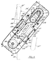
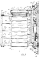
- FIGURE 4 shows that the mechanism for operating the arms 37 and 38 is contained within a housing whose front wall 42 appears in FIGURE 4 and whose rear wall 43 appears in FIGURE 5. In the latter figure the end walls 44 and 45 of the housing are also visible.
- the housing is much like a box whose rear wall 43 is fastened to the front face plate 22 of the machine depicted in FIGURE 1.
- the rotatable axle shafts 39 and 40 have tooth wheels in the form of sprockets 46 and 47 fastened to them.
- Sprocket 46 is bolted to a clamp 48 which provides for clamping the sprocket to axle shaft 39 by way of tightening a clamping screw 49.
- a key and keyway may also engage the sprocket to the axle shaft.
- the other sprocket 47 is similarly bolted to a clamping member 50 which is provided with a screw 51 which can be tightened to clamp the sprocket to axle shaft 40.
- Axle shaft 40 is journaled in ball bearings 52 and 53 which are set in suitable counterbored holes in the front and rear walls 42 and 43, respectively, of the drive mechanism housing.
- the other axle shaft 39 is similarly journaled for rotation in ball bearings 54 and 55.
- Swinging arm 37 is clamped to axle shaft 39 by means of a clamping element 56 which is essentially a split ring that is engaged to the shaft by tightening a machine screw 57.
- Swinging arm 38 is similarly clamped to axle shaft 40 by means of a clamping member 58.
- the previously mentioned outfeed roller 46 is shown in FIGURE 5 to be journaled for rotation on axle shaft 39 by means of two internal bearings 59 and 60.
- roller 36 is secured against shifting axially by collars 61 and 62 which are clamped to axle shaft 39.
- Tubular roller 36 is preferably composed of a strong lightweight material so the roller has low inertia and requires the least amount of torque to start and stop.
- infeed roller 35 as shown in FIGURE 5, is journaled for rotation on axle shaft 40.
- Roller 35 is prevented shifting axially on axle shaft 40 by means of axially spaced apart collars 64 and 65 which are clamped to axle shaft 40. From inspection of FIGURE 5, it will be evident that arms 37 and 38 swing in planes which are parallel to each other.
- arm 37 has mounted to it several rollers 70, 71, 72 and 73. These rollers are freely rotatable on respective shafts 74, 75, 76 and 77. Arm 38 has mounted to it an equal number of rollers 78-81. These rollers are mounted for rotation on respective shafts 82, 83, 84 and 85. Roller 78 is typical. It is also preferably composed of a lightweight rigid material for the sake of minimizing inertia. Roller 78 is journaled for rotation on shaft 82 by means of two ball bearings 86 and 87. The outboard end of shaft 82 is provided with a c-ring 88 for retaining bearing 87 on the shaft. The other bearing 86 is pressed on the shaft and retained against axial movement by abutting a shoulder 89 on the shaft 82. Typical roller shaft 82 is mounted to arm 38 by means of a machine screw 90.
- arms 37 and 38 are driven rotationally, in this illustrative embodiment, by means of two pneumatic actuators 96 and 97, whose piston rods 98 and 104 are interconnected by two chains 115 and 118.
- the chains engage the toothed wheels or sprockets 46 and 47 for rotating the axle shafts 39 and 40 and the arms 37 and 38 thereon to accumulate web in response to movement of the pistons 100 and 101.
- the continued draw on the web at the outfeed causes the arms to swing toward each other.
- arms 37 and 38 are both rotated through an angle relative to imaginary center line 41 which provides for storing the maximum length of web 11 in the loops of web spanning between the arms. Arms 37 and 38 are swung by the greatest angular amount as in FIGURE 2 when web 11 is being fed into infeed roll 35 and is being drawn out of the accumulator over outfeed roll 36. In FIGURE 7, arms 37 and 38 are swung close to each other which is a condition that occurs when infeed of web 11 is stopped and the accumulator has paid out just about all of the web it is permitted to pay out over the outfeed roller 36 before infeed of web must continue.
- the manner in which the arms 37 and 38 are induced to swing out as in FIGURE 2 for storing the maximum amount and are allowed to yield toward each other as in FIGURE 7 to give up the stored amount of web will now be discussed in more detail in reference to FIGURES 4 and 5.
- a sprocket 47 is fastened to axle shaft 40 for the infeed roller 36 and another sprocket 46 is fastened to the outfeed roller axle shaft 39.
- Two pneumatic actuators 96 and 97 are mounted to the wall 42 of the housing.
- Actuator 96 has a piston rod 98 which extends slidably and sealably through both ends of the cylinder of actuator 96.
- the piston fixed to rod 98 is drawn in solid lines and is marked 100. Under ordinary operating conditions, that is, when arms 37 and 38 are swung through the maximum angle relative to center line 41, piston 100 will be shifted by air pressure to its phantom line position designated by the numeral 100'.
- Actuator 97 is similar to actuator 96.
- piston 101 in actuator 97 is positioned as shown in hidden lines.
- the volume 102 on one side of piston 100 is occupied by air under pressure under all operating conditions of the accumulator. The pressure tends to force piston 100 to the left to develop a force which is translated to web tension.
- piston 101 is biased to the right in FIGURE 4.
- the piston rod 104 of actuator 97 also extends through both ends of the actuator cylinder 105.
- Pressurized air is supplied to the pressurizing volumes 102 and 103 of the actuators through a supply line 106.
- the pressurized air enters actuator 97 by way of inlet elbow 107 and pressurized air enters actuator 96 through an elbow 108.
- the filters also prevent air containing contaminants from being drawn into the actuator cylinders when the pistons retract to their home positions depicted in FIGURE 4.
- a flexible member in the form of a chain 115 has one of its end 116 connected to an end of piston rod 98 of actuator 96 and has its other end 117 connected to an end of piston rod 104 of actuator 97.
- Chain 115 is engaged with sprocket 46 for driving axle shaft 39.
- Another chain 118 has one of its ends 119 fastened to piston rod 98 of actuator 96 and the other of its ends 120 fastened to the piston rod 104 of actuator 97. It would be possible to use toothed pulleys in place of sprockets 46 and 47 and to use toothed timing belts in conjunction with the pulleys instead of using chains.
- the arms 37 and 38 rotate to the position in which they are depicted in FIGURE 2 wherein they store the maximum amount of web in the loops between the rollers 70-73 and 78-81 on the respective arms 37 and 38.
- the web is fed into the accumulator at a speed regulated by the position of the arms. This will cause the infeed web speed to equal outfeed web speed when the arms are positioned for optimum web storage. This will place the arms approximately as shown in FIGURE 2, with the air cylinder piston 100 at position 100', as shown in FIGURE 4.
- axle shafts 39 and 40 for the arms are driven together the arms always will counterbalance each other. It should also be noted that the shafts and the arms swing clockwise together as they are accumulating a length of web in loops between them and that they rotate counterclockwise together when infeed of web is interrupted and outfeed continues as a result of web being drawn by whatever web consuming or utilizing device is being supplied with the web from the accumulator.
- FIGURES 4 and 5 Observe in FIGURES 4 and 5 that there is another sprocket 125 fastened to axle shaft 39.
- a chain loop 126 runs over the sprocket for the purpose of driving another sprocket 127.
- Sprocket 127 is fastened to the shaft 128 of a potentiometer 129.
- the lead wires, not shown, come in through a connector 132.
- the potentiometer is supported on a bracket 130 which is clamped to the front wall 42 of the drive mechanism housing by means of machine bolts, such as the one marked 131, which pass through slotted holes in the bracket to provide for shifting the potentiometer until the proper tension is obtained in chain 126.
- the potentiometer produces an analog signal relating to the angular position of the arms.
- This analog signal is typically supplied to the infeed device's web speed controller, not shown.
- the motor being controlled is the previously mentioned motor coupled to the shaft 21 of the belt drive mechanism 16. If, during regular operation, draw of web at the outfeed of the accumulator 10 increases such as to cause an angular change in the arm position of the accumulator, for example, the controller will cause the motor which drives the belt drive 16 to run faster until normal arm position is restored.
- a feature of the invention is the ease with which the web can be threaded through the accumulator to begin a web run without the need for zigzagging the web around the rollers on the arms 37 and 38. Attention is invited to FIGURE 6.
- arms 37 and 38 are crossed over each other as compared with their angular positions in FIGURE 2 and 3, for example. Cross-over can be effected by grasping the outboard end of arm 38, for example, and drawing it past arm 37. Because the arms swing through an angle relative to the imaginary center line which runs through the axes of shafts 39 and 40 and the rollers on each of the arms are offset from each other as they pass the center line, the rollers on one arm can pass through the space between rollers on the other arm .
- manually deflected arm 38 has been released and tension is being applied to the web which causes the arms to swing past each other again.
- the arms then slowly swing away from each other in response to the pressure that is applied to the pistons in the pneumatic actuators 96 and 97.
- the actual tension induced in the web by the torsional force applied to the arms is a trigonometric function of the angular relationship between the various web strands and the arms.
- relatively constant web tension can be achieved, for example, by having a microprocessor based controller, not shown, vary the actuator pressure in dependence on the signal received from the potentiometer 129.
- An alternative embodiment of the accumulator depicted in FIGURES 8-10 overcomes the variable torque requirement by a purely mechanical rather than electrical method.
- parts which are similar to parts identified in the previously discussed embodiment are given the same reference numerals.
- a varying radius cam 150 is fastened to axle shaft 40 along with sprocket 47.
- a closed loop chain 151 wraps around sprocket 47 and also around sprocket 46 which is on the other axle shaft 49. It will be evident that when one sprocket is forced to turn the other will turn through the same angle and the arms 37 and 38 will swing through a corresponding angle relative to a line passing through the centers of axle shafts 39 and 40.
- a short piece of chain 152 is fastened at one end 153 to the cam and is fastened at the other of its end 154 to the end of a piston rod 155. Piston rod 155 extends from the cylinder 156 of a pneumatic actuator 157.
- Cylinder 156 can swivel on a bracket 170.
- the cylinder has an inlet 164 for pressurized air and a filter-muffler 165.
- the end 153 of the chain 152 attaches to the curved cam 150 at the place where the radius of the profile 158 of the cam is minimum.
- the radius of the cam increases continually from the point 153 to the end 159 of the cam where the radius of the cam is largest.
- the effective radius or moment of rotation arm is that point at which the chain becomes tangent to the cam profile 158. From this, it can be seen that a constant force applied by the pneumatic actuator can produce a torsional force in the arms which varies with angular position.
- the varying radii of the cam are selected to compensate for the varying force vector between the web and arm angles, resulting in an effectively constant web tension, regardless of arm position.
- FIGURE 9 illustrates this situation where the chain 152 is tangent to the profile 158 of the cam at a point marked 162.
- the radius of the cam at this point is marked 160.
- the radius extending from the center of shaft 40 to the point of tangency between the chain and the profile 158 of the cam is marked 163. It will be evident that the radius 160 in FIGURE 9 where the arms are close to each other is substantially greater than the radius 163 in FIGURE 8 where the arms 37 and 38 are angulated farther apart in FIGURE 8 than they are in FIGURE 9.
- the pressurized air is supplied to actuator cylinder 156 through a tube 164.
- the cylinder is also provided with a combination muffler and filter 165 which prevents contaminated air being drawn into the cylinder 156 when the piston moves in opposition to the air pressure due to arms 37 and 38 being forced toward each other while web infeed is stopped for an interval.
- FIGURE 10 shows how axle shaft 40 is journaled for rotation in ball bearings 52 and 53 which are set in walls 42 and 43 of the mechanism housing as is the case in the previously described embodiment.
- cam 150 is fastened to shaft 40 and sprocket 47 is fastened to a member 166.
- Chain 152 is pivotally connected to cam 150 with a pin 167 as is evident from inspection.
- actuators which differ from the two pneumatic actuators 96 and 97 in the FIGURE 4 embodiment and the single actuator 157 in the FIGURE 9 embodiment can be employed to swing arms 37 and 38 apart and have the arms swing toward each other.
- a version of the accumulator not illustrated, has been constructed and satisfactorily operated wherein a torsion spring, not shown, serves as the actuator.
- the torsion spring has one end fixed and its other end fastened to one of the axle shafts 39 or 40. During regular web transport the preloaded torsion spring causes the arms 37 and 38 to swing away from opposite sides of the center line.
- a commercially available torque motor is mechanically coupled to one of the axle shafts.
- the axle shafts are connected for being driven in unison by a closed loop chain.
- the torque motor can be caused to vary its torque in accordance with its rotational angle.
Landscapes
- Controlling Rewinding, Feeding, Winding, Or Abnormalities Of Webs (AREA)
- Replacement Of Web Rolls (AREA)
- Treatment Of Fiber Materials (AREA)
- Manufacturing Of Cigar And Cigarette Tobacco (AREA)
- Folding Of Thin Sheet-Like Materials, Special Discharging Devices, And Others (AREA)
Applications Claiming Priority (2)
| Application Number | Priority Date | Filing Date | Title |
|---|---|---|---|
| US69049391A | 1991-04-24 | 1991-04-24 | |
| US690493 | 1991-04-24 |
Publications (2)
| Publication Number | Publication Date |
|---|---|
| EP0510251A1 true EP0510251A1 (fr) | 1992-10-28 |
| EP0510251B1 EP0510251B1 (fr) | 1995-06-14 |
Family
ID=24772686
Family Applications (1)
| Application Number | Title | Priority Date | Filing Date |
|---|---|---|---|
| EP19910116658 Expired - Lifetime EP0510251B1 (fr) | 1991-04-24 | 1991-09-30 | Emmagasinage temporaire avec bras opposés pour tissues |
Country Status (4)
| Country | Link |
|---|---|
| EP (1) | EP0510251B1 (fr) |
| CA (1) | CA2052180A1 (fr) |
| DE (1) | DE69110451T2 (fr) |
| ES (1) | ES2075292T3 (fr) |
Cited By (15)
| Publication number | Priority date | Publication date | Assignee | Title |
|---|---|---|---|---|
| EP0999161A1 (fr) * | 1998-10-21 | 2000-05-10 | Sachsenring Maschinenbau GmbH | Dispositif pour compenser le mouvement d'avance d'une bande de film |
| US8377249B2 (en) | 2009-04-03 | 2013-02-19 | The Procter & Gamble Company | Appraratus and method for providing a localized speed variance of an advancing substrate |
| US9144624B2 (en) | 2013-07-19 | 2015-09-29 | The Procter & Gamble Company | Method for providing a localized dwell in an advancing web |
| US9603752B2 (en) | 2010-08-05 | 2017-03-28 | Curt G. Joa, Inc. | Apparatus and method for minimizing waste and improving quality and production in web processing operations by automatic cuff defect correction |
| US9622918B2 (en) | 2006-05-18 | 2017-04-18 | Curt G. Joe, Inc. | Methods and apparatus for application of nested zero waste ear to traveling web |
| US9809414B2 (en) | 2012-04-24 | 2017-11-07 | Curt G. Joa, Inc. | Elastic break brake apparatus and method for minimizing broken elastic rethreading |
| US9907706B2 (en) | 2011-02-25 | 2018-03-06 | Curt G. Joa, Inc. | Methods and apparatus for forming disposable products at high speeds with small machine footprint |
| US9944487B2 (en) | 2007-02-21 | 2018-04-17 | Curt G. Joa, Inc. | Single transfer insert placement method and apparatus |
| US9950439B2 (en) | 2007-02-21 | 2018-04-24 | Curt G. Joa, Inc. | Single transfer insert placement method and apparatus with cross-direction insert placement control |
| EP3385203A1 (fr) * | 2017-04-07 | 2018-10-10 | Mespack, S.L. | Dispositif de compensation de mouvement de bande pelliculaire pour une compensation de mouvement de bande pelliculaire entre une section de mouvement vers l'avant continu et une section de mouvement vers l'avant intermittent |
| US10167156B2 (en) | 2015-07-24 | 2019-01-01 | Curt G. Joa, Inc. | Vacuum commutation apparatus and methods |
| US10456302B2 (en) | 2006-05-18 | 2019-10-29 | Curt G. Joa, Inc. | Methods and apparatus for application of nested zero waste ear to traveling web |
| US10751220B2 (en) | 2012-02-20 | 2020-08-25 | Curt G. Joa, Inc. | Method of forming bonds between discrete components of disposable articles |
| CN116443640A (zh) * | 2023-06-15 | 2023-07-18 | 苏州江天包装科技股份有限公司 | 逐级分解式印刷制品的在线张力调节系统 |
| US11737930B2 (en) | 2020-02-27 | 2023-08-29 | Curt G. Joa, Inc. | Configurable single transfer insert placement method and apparatus |
Families Citing this family (15)
| Publication number | Priority date | Publication date | Assignee | Title |
|---|---|---|---|---|
| US7374627B2 (en) | 2004-04-19 | 2008-05-20 | Curt G. Joa, Inc. | Method of producing an ultrasonically bonded lap seam |
| US7303708B2 (en) | 2004-04-19 | 2007-12-04 | Curt G. Joa, Inc. | Super absorbent distribution system design for homogeneous distribution throughout an absorbent core |
| US7640962B2 (en) | 2004-04-20 | 2010-01-05 | Curt G. Joa, Inc. | Multiple tape application method and apparatus |
| US7638014B2 (en) | 2004-05-21 | 2009-12-29 | Curt G. Joa, Inc. | Method of producing a pants-type diaper |
| US7537215B2 (en) | 2004-06-15 | 2009-05-26 | Curt G. Joa, Inc. | Method and apparatus for securing stretchable film using vacuum |
| EP1868821B1 (fr) | 2005-03-09 | 2013-01-30 | Joa, Curt G., Inc. | Dispositif et procede d'application transversale d'un ruban adhesif |
| US7533709B2 (en) | 2005-05-31 | 2009-05-19 | Curt G. Joa, Inc. | High speed vacuum porting |
| US7618513B2 (en) | 2005-05-31 | 2009-11-17 | Curt G. Joa, Inc. | Web stabilization on a slip and cut applicator |
| US7398870B2 (en) | 2005-10-05 | 2008-07-15 | Curt G. Joa, Inc | Article transfer and placement apparatus |
| US9433538B2 (en) | 2006-05-18 | 2016-09-06 | Curt G. Joa, Inc. | Methods and apparatus for application of nested zero waste ear to traveling web and formation of articles using a dual cut slip unit |
| US9387131B2 (en) | 2007-07-20 | 2016-07-12 | Curt G. Joa, Inc. | Apparatus and method for minimizing waste and improving quality and production in web processing operations by automated threading and re-threading of web materials |
| US9089453B2 (en) | 2009-12-30 | 2015-07-28 | Curt G. Joa, Inc. | Method for producing absorbent article with stretch film side panel and application of intermittent discrete components of an absorbent article |
| US9283683B2 (en) | 2013-07-24 | 2016-03-15 | Curt G. Joa, Inc. | Ventilated vacuum commutation structures |
| US9289329B1 (en) | 2013-12-05 | 2016-03-22 | Curt G. Joa, Inc. | Method for producing pant type diapers |
| CN109279422A (zh) * | 2018-12-03 | 2019-01-29 | 广东佰分爱卫生用品有限公司 | 一种大宽幅无纺布用于连续生产的自动储料设备 |
Citations (5)
| Publication number | Priority date | Publication date | Assignee | Title |
|---|---|---|---|---|
| GB1244066A (en) * | 1968-09-13 | 1971-08-25 | Ind Companie Kleinweffers Plas | Accumulator, compensator or the like, for endless material web |
| DE2259844A1 (de) * | 1971-12-10 | 1973-06-20 | Jean Duplessy | Vorrichtung zum abgeben eines fadens od. eines anderen strang- oder seilfoermigen gegenstandes unter angenaehert konstanter spannung |
| DE3327636A1 (de) * | 1983-07-30 | 1985-02-07 | Franz Bendig | Bewegungsausgleichsvorrichtung fuer folienbahnen |
| US4603800A (en) * | 1984-03-22 | 1986-08-05 | Focke & Co., (Gmbh & Co.) | Apparatus for transporting sheets of packaging material |
| GB2206869A (en) * | 1987-07-10 | 1989-01-18 | Bwg Bergwerk Walzwerk | Strip treating apparatus |
-
1991
- 1991-09-24 CA CA 2052180 patent/CA2052180A1/fr not_active Abandoned
- 1991-09-30 ES ES91116658T patent/ES2075292T3/es not_active Expired - Lifetime
- 1991-09-30 EP EP19910116658 patent/EP0510251B1/fr not_active Expired - Lifetime
- 1991-09-30 DE DE1991610451 patent/DE69110451T2/de not_active Expired - Fee Related
Patent Citations (5)
| Publication number | Priority date | Publication date | Assignee | Title |
|---|---|---|---|---|
| GB1244066A (en) * | 1968-09-13 | 1971-08-25 | Ind Companie Kleinweffers Plas | Accumulator, compensator or the like, for endless material web |
| DE2259844A1 (de) * | 1971-12-10 | 1973-06-20 | Jean Duplessy | Vorrichtung zum abgeben eines fadens od. eines anderen strang- oder seilfoermigen gegenstandes unter angenaehert konstanter spannung |
| DE3327636A1 (de) * | 1983-07-30 | 1985-02-07 | Franz Bendig | Bewegungsausgleichsvorrichtung fuer folienbahnen |
| US4603800A (en) * | 1984-03-22 | 1986-08-05 | Focke & Co., (Gmbh & Co.) | Apparatus for transporting sheets of packaging material |
| GB2206869A (en) * | 1987-07-10 | 1989-01-18 | Bwg Bergwerk Walzwerk | Strip treating apparatus |
Cited By (27)
| Publication number | Priority date | Publication date | Assignee | Title |
|---|---|---|---|---|
| EP0999161A1 (fr) * | 1998-10-21 | 2000-05-10 | Sachsenring Maschinenbau GmbH | Dispositif pour compenser le mouvement d'avance d'une bande de film |
| US9622918B2 (en) | 2006-05-18 | 2017-04-18 | Curt G. Joe, Inc. | Methods and apparatus for application of nested zero waste ear to traveling web |
| US10456302B2 (en) | 2006-05-18 | 2019-10-29 | Curt G. Joa, Inc. | Methods and apparatus for application of nested zero waste ear to traveling web |
| US10266362B2 (en) | 2007-02-21 | 2019-04-23 | Curt G. Joa, Inc. | Single transfer insert placement method and apparatus |
| US9944487B2 (en) | 2007-02-21 | 2018-04-17 | Curt G. Joa, Inc. | Single transfer insert placement method and apparatus |
| US9950439B2 (en) | 2007-02-21 | 2018-04-24 | Curt G. Joa, Inc. | Single transfer insert placement method and apparatus with cross-direction insert placement control |
| US9090050B2 (en) | 2009-04-03 | 2015-07-28 | The Procter & Gamble Company | Apparatus and method for providing a localized speed variance of an advancing substrate |
| US9050787B2 (en) | 2009-04-03 | 2015-06-09 | The Procter & Gamble Company | Apparatus and method for providing a localized speed variance of an advancing substrate |
| US8377249B2 (en) | 2009-04-03 | 2013-02-19 | The Procter & Gamble Company | Appraratus and method for providing a localized speed variance of an advancing substrate |
| US10702428B2 (en) | 2009-04-06 | 2020-07-07 | Curt G. Joa, Inc. | Methods and apparatus for application of nested zero waste ear to traveling web |
| US9603752B2 (en) | 2010-08-05 | 2017-03-28 | Curt G. Joa, Inc. | Apparatus and method for minimizing waste and improving quality and production in web processing operations by automatic cuff defect correction |
| USRE48182E1 (en) | 2010-08-05 | 2020-09-01 | Curt G. Joa, Inc. | Apparatus and method for minimizing waste and improving quality and production in web processing operations by automatic cuff defect correction |
| US9907706B2 (en) | 2011-02-25 | 2018-03-06 | Curt G. Joa, Inc. | Methods and apparatus for forming disposable products at high speeds with small machine footprint |
| US10751220B2 (en) | 2012-02-20 | 2020-08-25 | Curt G. Joa, Inc. | Method of forming bonds between discrete components of disposable articles |
| US11034543B2 (en) | 2012-04-24 | 2021-06-15 | Curt G. Joa, Inc. | Apparatus and method for applying parallel flared elastics to disposable products and disposable products containing parallel flared elastics |
| US9908739B2 (en) | 2012-04-24 | 2018-03-06 | Curt G. Joa, Inc. | Apparatus and method for applying parallel flared elastics to disposable products and disposable products containing parallel flared elastics |
| US9809414B2 (en) | 2012-04-24 | 2017-11-07 | Curt G. Joa, Inc. | Elastic break brake apparatus and method for minimizing broken elastic rethreading |
| US9144624B2 (en) | 2013-07-19 | 2015-09-29 | The Procter & Gamble Company | Method for providing a localized dwell in an advancing web |
| US10633207B2 (en) | 2015-07-24 | 2020-04-28 | Curt G. Joa, Inc. | Vacuum commutation apparatus and methods |
| US10494216B2 (en) | 2015-07-24 | 2019-12-03 | Curt G. Joa, Inc. | Vacuum communication apparatus and methods |
| US10167156B2 (en) | 2015-07-24 | 2019-01-01 | Curt G. Joa, Inc. | Vacuum commutation apparatus and methods |
| WO2018185141A1 (fr) | 2017-04-07 | 2018-10-11 | Mespack, Sl | Dispositif de compensation de mouvement de film en bande pour une compensation de mouvement de film en bande entre une section de mouvement avant continue et une section de mouvement avant intermittente |
| EP3385203A1 (fr) * | 2017-04-07 | 2018-10-10 | Mespack, S.L. | Dispositif de compensation de mouvement de bande pelliculaire pour une compensation de mouvement de bande pelliculaire entre une section de mouvement vers l'avant continu et une section de mouvement vers l'avant intermittent |
| US11046542B2 (en) | 2017-04-07 | 2021-06-29 | Mespack, Sl | Web film movement compensating device for a web film movement compensation between a continuous forward movement section and an intermittent forward movement section |
| US11737930B2 (en) | 2020-02-27 | 2023-08-29 | Curt G. Joa, Inc. | Configurable single transfer insert placement method and apparatus |
| CN116443640A (zh) * | 2023-06-15 | 2023-07-18 | 苏州江天包装科技股份有限公司 | 逐级分解式印刷制品的在线张力调节系统 |
| CN116443640B (zh) * | 2023-06-15 | 2023-09-05 | 苏州江天包装科技股份有限公司 | 逐级分解式印刷制品的在线张力调节系统 |
Also Published As
| Publication number | Publication date |
|---|---|
| DE69110451D1 (de) | 1995-07-20 |
| ES2075292T3 (es) | 1995-10-01 |
| CA2052180A1 (fr) | 1992-10-25 |
| EP0510251B1 (fr) | 1995-06-14 |
| DE69110451T2 (de) | 1995-10-26 |
Similar Documents
| Publication | Publication Date | Title |
|---|---|---|
| US5163594A (en) | Opposed arm web accumulator | |
| EP0510251B1 (fr) | Emmagasinage temporaire avec bras opposés pour tissues | |
| US4480801A (en) | Webbing system | |
| US20050230449A1 (en) | Apparatus and method of increasing web storage in a dancer | |
| EP0989084A2 (fr) | Accumulateur de bande avec compensation de poids | |
| EP0865402B1 (fr) | Mecanisme et methode d'etirement d'une pellicule | |
| US5516058A (en) | Method and apparatus for taking up narrow sheet member | |
| JPS63295349A (ja) | 貯蔵装置 | |
| JPH07108741B2 (ja) | 輪転機の紙通し装置 | |
| US5377931A (en) | Apparatus for reeling a wound web reel | |
| US4274574A (en) | Linear motion cable drive | |
| WO1992002417A1 (fr) | Machine servant a lier un faisceau de cables au moyen d'une bande | |
| GB2072128A (en) | Strapping apparatus feed and tension mechanism | |
| SE435483B (sv) | Anordning for avlindning av ventilseckar bestaende overlappningsbandvalsar | |
| US4664329A (en) | Wire coiler | |
| US3515327A (en) | Apparatus for storing a variable length of strip | |
| US6716317B2 (en) | Tension decurler for web material | |
| US4640164A (en) | High speed wire cutter | |
| US4369934A (en) | Helical filament winding apparatus | |
| EP0494708B1 (fr) | Dispositif d'entrainement d'un fil | |
| US4655379A (en) | Wire transport conduit | |
| US5022595A (en) | Tensioning device | |
| US20040250510A1 (en) | Apparatus and method for dispensing wrapper and wrapping products | |
| JPS60102370A (ja) | 蓄線装置 | |
| US20050029389A1 (en) | Web winding apparatus having traveling, gimbaled cinch roller and winding method |
Legal Events
| Date | Code | Title | Description |
|---|---|---|---|
| PUAI | Public reference made under article 153(3) epc to a published international application that has entered the european phase |
Free format text: ORIGINAL CODE: 0009012 |
|
| AK | Designated contracting states |
Kind code of ref document: A1 Designated state(s): CH DE ES FR GB IT LI SE |
|
| 17P | Request for examination filed |
Effective date: 19921123 |
|
| 17Q | First examination report despatched |
Effective date: 19940323 |
|
| GRAA | (expected) grant |
Free format text: ORIGINAL CODE: 0009210 |
|
| AK | Designated contracting states |
Kind code of ref document: B1 Designated state(s): CH DE ES FR GB IT LI SE |
|
| REF | Corresponds to: |
Ref document number: 69110451 Country of ref document: DE Date of ref document: 19950720 |
|
| ITF | It: translation for a ep patent filed | ||
| REG | Reference to a national code |
Ref country code: ES Ref legal event code: FG2A Ref document number: 2075292 Country of ref document: ES Kind code of ref document: T3 |
|
| ET | Fr: translation filed | ||
| PLBE | No opposition filed within time limit |
Free format text: ORIGINAL CODE: 0009261 |
|
| STAA | Information on the status of an ep patent application or granted ep patent |
Free format text: STATUS: NO OPPOSITION FILED WITHIN TIME LIMIT |
|
| 26N | No opposition filed | ||
| PGFP | Annual fee paid to national office [announced via postgrant information from national office to epo] |
Ref country code: CH Payment date: 19971203 Year of fee payment: 7 |
|
| PG25 | Lapsed in a contracting state [announced via postgrant information from national office to epo] |
Ref country code: LI Free format text: LAPSE BECAUSE OF NON-PAYMENT OF DUE FEES Effective date: 19980930 Ref country code: CH Free format text: LAPSE BECAUSE OF NON-PAYMENT OF DUE FEES Effective date: 19980930 |
|
| REG | Reference to a national code |
Ref country code: CH Ref legal event code: PL |
|
| PGFP | Annual fee paid to national office [announced via postgrant information from national office to epo] |
Ref country code: GB Payment date: 20011001 Year of fee payment: 11 |
|
| PGFP | Annual fee paid to national office [announced via postgrant information from national office to epo] |
Ref country code: ES Payment date: 20011025 Year of fee payment: 11 |
|
| REG | Reference to a national code |
Ref country code: GB Ref legal event code: IF02 |
|
| PG25 | Lapsed in a contracting state [announced via postgrant information from national office to epo] |
Ref country code: GB Free format text: LAPSE BECAUSE OF NON-PAYMENT OF DUE FEES Effective date: 20020930 |
|
| PG25 | Lapsed in a contracting state [announced via postgrant information from national office to epo] |
Ref country code: ES Free format text: LAPSE BECAUSE OF NON-PAYMENT OF DUE FEES Effective date: 20021001 |
|
| GBPC | Gb: european patent ceased through non-payment of renewal fee |
Effective date: 20020930 |
|
| PGFP | Annual fee paid to national office [announced via postgrant information from national office to epo] |
Ref country code: FR Payment date: 20030922 Year of fee payment: 13 |
|
| PGFP | Annual fee paid to national office [announced via postgrant information from national office to epo] |
Ref country code: SE Payment date: 20030924 Year of fee payment: 13 |
|
| PGFP | Annual fee paid to national office [announced via postgrant information from national office to epo] |
Ref country code: DE Payment date: 20030926 Year of fee payment: 13 |
|
| REG | Reference to a national code |
Ref country code: ES Ref legal event code: FD2A Effective date: 20031011 |
|
| PG25 | Lapsed in a contracting state [announced via postgrant information from national office to epo] |
Ref country code: SE Free format text: LAPSE BECAUSE OF NON-PAYMENT OF DUE FEES Effective date: 20041001 |
|
| PG25 | Lapsed in a contracting state [announced via postgrant information from national office to epo] |
Ref country code: DE Free format text: LAPSE BECAUSE OF NON-PAYMENT OF DUE FEES Effective date: 20050401 |
|
| EUG | Se: european patent has lapsed | ||
| PG25 | Lapsed in a contracting state [announced via postgrant information from national office to epo] |
Ref country code: FR Free format text: LAPSE BECAUSE OF NON-PAYMENT OF DUE FEES Effective date: 20050531 |
|
| REG | Reference to a national code |
Ref country code: FR Ref legal event code: ST |
|
| PG25 | Lapsed in a contracting state [announced via postgrant information from national office to epo] |
Ref country code: IT Free format text: LAPSE BECAUSE OF NON-PAYMENT OF DUE FEES Effective date: 20050930 |