EP0510341A1 - Procédé pour commander le fonctionnement d'un réacteur de gazéification - Google Patents
Procédé pour commander le fonctionnement d'un réacteur de gazéification Download PDFInfo
- Publication number
- EP0510341A1 EP0510341A1 EP92104134A EP92104134A EP0510341A1 EP 0510341 A1 EP0510341 A1 EP 0510341A1 EP 92104134 A EP92104134 A EP 92104134A EP 92104134 A EP92104134 A EP 92104134A EP 0510341 A1 EP0510341 A1 EP 0510341A1
- Authority
- EP
- European Patent Office
- Prior art keywords
- fuel
- gasification
- ash
- gasification reactor
- water content
- Prior art date
- Legal status (The legal status is an assumption and is not a legal conclusion. Google has not performed a legal analysis and makes no representation as to the accuracy of the status listed.)
- Granted
Links
- 238000000034 method Methods 0.000 title claims abstract description 30
- 239000000446 fuel Substances 0.000 claims abstract description 57
- 238000002309 gasification Methods 0.000 claims abstract description 54
- XLYOFNOQVPJJNP-UHFFFAOYSA-N water Substances O XLYOFNOQVPJJNP-UHFFFAOYSA-N 0.000 claims abstract description 28
- 239000003795 chemical substances by application Substances 0.000 claims abstract description 13
- 239000000126 substance Substances 0.000 claims abstract description 11
- 238000012545 processing Methods 0.000 claims abstract description 6
- 239000000523 sample Substances 0.000 claims description 13
- 239000003245 coal Substances 0.000 claims description 8
- 238000004886 process control Methods 0.000 abstract 1
- 239000002893 slag Substances 0.000 description 6
- CURLTUGMZLYLDI-UHFFFAOYSA-N Carbon dioxide Chemical compound O=C=O CURLTUGMZLYLDI-UHFFFAOYSA-N 0.000 description 4
- 238000005259 measurement Methods 0.000 description 4
- 125000004429 atom Chemical group 0.000 description 3
- 229910052799 carbon Inorganic materials 0.000 description 3
- 239000007789 gas Substances 0.000 description 3
- 230000005855 radiation Effects 0.000 description 3
- OKTJSMMVPCPJKN-UHFFFAOYSA-N Carbon Chemical compound [C] OKTJSMMVPCPJKN-UHFFFAOYSA-N 0.000 description 2
- 229910052792 caesium Inorganic materials 0.000 description 2
- TVFDJXOCXUVLDH-UHFFFAOYSA-N caesium atom Chemical compound [Cs] TVFDJXOCXUVLDH-UHFFFAOYSA-N 0.000 description 2
- 229910002092 carbon dioxide Inorganic materials 0.000 description 2
- 239000001569 carbon dioxide Substances 0.000 description 2
- 238000001739 density measurement Methods 0.000 description 2
- 229910052739 hydrogen Inorganic materials 0.000 description 2
- 239000007788 liquid Substances 0.000 description 2
- 238000000691 measurement method Methods 0.000 description 2
- 238000011017 operating method Methods 0.000 description 2
- 229910052760 oxygen Inorganic materials 0.000 description 2
- 229910052695 Americium Inorganic materials 0.000 description 1
- UGFAIRIUMAVXCW-UHFFFAOYSA-N Carbon monoxide Chemical compound [O+]#[C-] UGFAIRIUMAVXCW-UHFFFAOYSA-N 0.000 description 1
- 230000006978 adaptation Effects 0.000 description 1
- 239000003570 air Substances 0.000 description 1
- LXQXZNRPTYVCNG-UHFFFAOYSA-N americium atom Chemical compound [Am] LXQXZNRPTYVCNG-UHFFFAOYSA-N 0.000 description 1
- QVGXLLKOCUKJST-UHFFFAOYSA-N atomic oxygen Chemical compound [O] QVGXLLKOCUKJST-UHFFFAOYSA-N 0.000 description 1
- 230000015572 biosynthetic process Effects 0.000 description 1
- 229910002091 carbon monoxide Inorganic materials 0.000 description 1
- 239000002817 coal dust Substances 0.000 description 1
- 238000013461 design Methods 0.000 description 1
- 230000006866 deterioration Effects 0.000 description 1
- 238000010586 diagram Methods 0.000 description 1
- 238000001035 drying Methods 0.000 description 1
- 230000000694 effects Effects 0.000 description 1
- 239000003792 electrolyte Substances 0.000 description 1
- 238000000265 homogenisation Methods 0.000 description 1
- 239000001257 hydrogen Substances 0.000 description 1
- 125000004435 hydrogen atom Chemical class [H]* 0.000 description 1
- 229910052500 inorganic mineral Inorganic materials 0.000 description 1
- 230000001788 irregular Effects 0.000 description 1
- 238000002844 melting Methods 0.000 description 1
- 230000008018 melting Effects 0.000 description 1
- 239000011707 mineral Substances 0.000 description 1
- 229910052757 nitrogen Inorganic materials 0.000 description 1
- 238000005457 optimization Methods 0.000 description 1
- 239000001301 oxygen Substances 0.000 description 1
- 235000011837 pasties Nutrition 0.000 description 1
- 230000002028 premature Effects 0.000 description 1
- 230000002285 radioactive effect Effects 0.000 description 1
- 239000000376 reactant Substances 0.000 description 1
- 239000007787 solid Substances 0.000 description 1
- 230000007704 transition Effects 0.000 description 1
Images
Classifications
-
- C—CHEMISTRY; METALLURGY
- C10—PETROLEUM, GAS OR COKE INDUSTRIES; TECHNICAL GASES CONTAINING CARBON MONOXIDE; FUELS; LUBRICANTS; PEAT
- C10J—PRODUCTION OF PRODUCER GAS, WATER-GAS, SYNTHESIS GAS FROM SOLID CARBONACEOUS MATERIAL, OR MIXTURES CONTAINING THESE GASES; CARBURETTING AIR OR OTHER GASES
- C10J3/00—Production of combustible gases containing carbon monoxide from solid carbonaceous fuels
- C10J3/72—Other features
- C10J3/723—Controlling or regulating the gasification process
-
- C—CHEMISTRY; METALLURGY
- C10—PETROLEUM, GAS OR COKE INDUSTRIES; TECHNICAL GASES CONTAINING CARBON MONOXIDE; FUELS; LUBRICANTS; PEAT
- C10J—PRODUCTION OF PRODUCER GAS, WATER-GAS, SYNTHESIS GAS FROM SOLID CARBONACEOUS MATERIAL, OR MIXTURES CONTAINING THESE GASES; CARBURETTING AIR OR OTHER GASES
- C10J3/00—Production of combustible gases containing carbon monoxide from solid carbonaceous fuels
- C10J3/46—Gasification of granular or pulverulent flues in suspension
- C10J3/466—Entrained flow processes
-
- C—CHEMISTRY; METALLURGY
- C10—PETROLEUM, GAS OR COKE INDUSTRIES; TECHNICAL GASES CONTAINING CARBON MONOXIDE; FUELS; LUBRICANTS; PEAT
- C10J—PRODUCTION OF PRODUCER GAS, WATER-GAS, SYNTHESIS GAS FROM SOLID CARBONACEOUS MATERIAL, OR MIXTURES CONTAINING THESE GASES; CARBURETTING AIR OR OTHER GASES
- C10J2300/00—Details of gasification processes
- C10J2300/09—Details of the feed, e.g. feeding of spent catalyst, inert gas or halogens
- C10J2300/0913—Carbonaceous raw material
- C10J2300/093—Coal
-
- C—CHEMISTRY; METALLURGY
- C10—PETROLEUM, GAS OR COKE INDUSTRIES; TECHNICAL GASES CONTAINING CARBON MONOXIDE; FUELS; LUBRICANTS; PEAT
- C10J—PRODUCTION OF PRODUCER GAS, WATER-GAS, SYNTHESIS GAS FROM SOLID CARBONACEOUS MATERIAL, OR MIXTURES CONTAINING THESE GASES; CARBURETTING AIR OR OTHER GASES
- C10J2300/00—Details of gasification processes
- C10J2300/12—Heating the gasifier
- C10J2300/1223—Heating the gasifier by burners
Definitions
- the invention relates to a method for controlling the operating sequence of a gasification reactor operating according to the entrained flow method for the gasification of finely divided carbonaceous fuels, in particular fine-grained to dusty coal, in which fuel and gasification agent are fed to the gasification reactor in a quantity ratio set as a function of the temperature in the gasification reactor.
- the operating conditions are normally set so that the slag can run off in the liquid state from the lower part of the gasification reactor, while the product gas produced, consisting mainly of carbon monoxide and hydrogen, is withdrawn upward from the gasification reactor.
- the operating temperature in the gasification reactor must therefore always be about 100 - 400 ° C above the slag melting temperature, whereby the gasification can be operated both under increased pressure and under normal pressure. Because of the short residence times of the reactants in the gasification reactor, the aim is to supply fuel and gasification agents, such as air, oxygen, water vapor and carbon dioxide, to the gasification reactor in a constant quantity ratio during the entire process.
- the quantity ratio must be set so that neither a lack of fuel nor an excess of fuel occurs. Only if this condition is met can the Operating temperature in the gasification reactor can be kept within the range specified above.
- a lack of fuel leads to the undesirable formation of carbon dioxide with increasing operating temperature and thus to a deterioration in the ratio of the calorific efficiency of the product gas produced to the calorific value of the fuel used.
- excess fuel reduces the degree of gasification of the carbon due to the presence of non-gasified carbon.
- the temperature in the gasification reactor drops and can reach such low values that the liquid slag becomes pasty to solid, the slag removal is at risk and the operation is finally interrupted due to clogging of the slag removal.
- both streams in one such quantity ratio are introduced into the gasification reactor that the operating temperature can be kept within the temperature range mentioned above.
- the crucial ratio between fuel and gasification agent is to be formed from the combustible substance of the fuel, i.e. without its ash and water content.
- the ash and water content of the fuel used must be known. So far, it has therefore been customary for the ash and water content of the fuel to be determined at irregular intervals by laboratory analyzes on individual samples.
- the invention is therefore based on the object of improving the method of the type mentioned in such a way that, even in the event of sudden changes in the ash and / or water content of the fuel used, the temperature and operating conditions in the gasification reactor can be stabilized in such a way that the negative effects described above Consequences are avoided.
- the method of the type mentioned at the outset which is used to achieve this object is characterized in that the ash and water content of the fuel is determined simultaneously and continuously before it enters the gasification reactor and that the ratio of fuel to the processing of both measured values in a process computer Gasifying agent is adapted to the amount of combustible substance actually present in the fuel.
- the ash content can be determined by radiometric determination. This method of measurement is already used in coal processing and is described, for example, in the journal "Processing Technology", No. 11/1988, pages 648-653.
- the principle of measurement is that the fuel to be examined is irradiated simultaneously or at short distance from two radioactive sources, the radiation on different Send out energy levels. These are preferably Cs 137 and Am 241 lamps.
- the high-energy radiation of cesium has the property of being absorbed to the same extent by all atom types present in the fuel.
- the americium radiation is weakened by the atoms (Si, Al, Fe, Ca) which are characteristic of the ash substance significantly more than by the atoms of the combustible substance (C, H, O, N).
- the difference between the signals of the Cs 137 and Am 241 emitters is also a measure of how much the ash content at the measuring point differs from that in the calibration state.
- the difference signal can therefore be defined as the ash content of the fuel and used to correct the ratio of fuel flow to gasification medium flow.
- the capacitive measuring method which takes advantage of the high dielectric constant of the water compared to the dry substance, is particularly suitable for determining the water content. This is about 2 to 5 for coal and ash and about 80 for water.
- the dielectric constant is determined by means of a capacitive probe for the fuel flow in the measuring cross section.
- the measurement is only successful if the density of the fuel flow in the measuring section is also determined by radiometric density measurement, for example using a cesium emitter.
- the water content of the fuel can be determined by combining the two measured values.
- the measurement method described above fails when the fuel used has a high electrolyte content.
- the determination of the water content is expediently carried out using microwaves.
- the measuring probes for determining the ash and water content in the feed line of the fuel are arranged in close proximity to one another in the gasification reactor.
- Another design option is to also install the two measuring probes in the immediate vicinity of one another in the feed line close to the outlet of the supply container. If necessary, the measuring probes can finally also be installed in the allotment container itself.
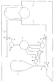
- the figure shows the flow diagram of a system for carrying out the method according to the invention, in which the measuring probes for determining the ash and water content of the fuel are arranged in close proximity to one another in the feed line close to the outlet of the feed container for the fuel.
- the gasification reactor 1 has two gasification burners 2.
- the number of gasification burners 2 can of course be arbitrary.
- the gasification burners 2 are supplied with fuel via the lines 3 and with gasification agent via the lines 4.
- the lines 3 branch off from the distributor 5, which in turn is connected to the supply container 7 for the fuel via the feed line 6.
- the measuring probes 8, 9 and 10 are installed in close proximity to one another.
- the delivery density of the fuel flow in the feed line 6 is determined radiometrically by the measuring probe 8, which contains a Cs 137 radiator.
- the measuring probe 9, which contains an Am 241 radiator makes it possible, using the reference signal from the measuring probe 8, to determine the ash content in the fuel stream, which is carried out in the manner described above.
- the measuring probe 10 is finally used to determine the water content by the capacitive method or microwave method in connection with the density measurement by the measuring probe 8.
- the measurement results found are transferred from the measuring probes 8 to 10 to the process computer 11, where the ash and Water content of the fuel is determined.
- the fuel mass flow is determined by the measuring device 12 installed in line 3. All data are therefore known which are necessary for the determination of the combustible substance actually present (ash and water-free).
- the determined result is transferred from the process computer 11 to the control circuit 13, by means of which the gasification agent supply in line 4 is adapted to the target value of combustible substance and gasification agent.
- the measuring device 14 is used to measure the amount of gasification in the line 4, which amount can be controlled by the control valve 15.
- a control valve 16 is also installed in line 3 and, together with the measuring device 12, forms the control circuit 17 for the fuel supply, so that the required adaptation to the setpoint value of combustible substance and gasifying agent can optionally also be carried out by changing the fuel supply.
- the regulation described above only for one gasification burner 2 must also apply to the second and each further one Gasification burner of the gasification reactor 1 apply.
Landscapes
- Chemical & Material Sciences (AREA)
- Engineering & Computer Science (AREA)
- Combustion & Propulsion (AREA)
- Oil, Petroleum & Natural Gas (AREA)
- Organic Chemistry (AREA)
- Gasification And Melting Of Waste (AREA)
- Processing Of Solid Wastes (AREA)
Applications Claiming Priority (2)
| Application Number | Priority Date | Filing Date | Title |
|---|---|---|---|
| DE19914113447 DE4113447A1 (de) | 1991-04-25 | 1991-04-25 | Verfahren zur steuerung des betriebsablaufes eines vergasungsreaktors |
| DE4113447 | 1991-04-25 |
Publications (2)
| Publication Number | Publication Date |
|---|---|
| EP0510341A1 true EP0510341A1 (fr) | 1992-10-28 |
| EP0510341B1 EP0510341B1 (fr) | 1994-06-08 |
Family
ID=6430297
Family Applications (1)
| Application Number | Title | Priority Date | Filing Date |
|---|---|---|---|
| EP19920104134 Expired - Lifetime EP0510341B1 (fr) | 1991-04-25 | 1992-03-11 | Procédé pour commander le fonctionnement d'un réacteur de gazéification |
Country Status (4)
| Country | Link |
|---|---|
| EP (1) | EP0510341B1 (fr) |
| DE (2) | DE4113447A1 (fr) |
| DK (1) | DK0510341T3 (fr) |
| ES (1) | ES2055626T3 (fr) |
Cited By (2)
| Publication number | Priority date | Publication date | Assignee | Title |
|---|---|---|---|---|
| WO2010114650A1 (fr) * | 2009-03-30 | 2010-10-07 | General Electric Company | Capteurs à fibres optiques intégrées pour systèmes de mesure en milieu agressif |
| EP3726202A1 (fr) * | 2019-04-15 | 2020-10-21 | L'air Liquide, Société Anonyme Pour L'Étude Et L'exploitation Des Procédés Georges Claude | Procédé de commande en ligne d'un processus de gazéification formant des mâchefers et installation pour un processus de gazéification |
Families Citing this family (3)
| Publication number | Priority date | Publication date | Assignee | Title |
|---|---|---|---|---|
| DE102009015736B4 (de) * | 2009-03-31 | 2013-05-23 | Siemens Aktiengesellschaft | Einstellung der Vergasungsparameter für Flugstromvergaser hoher Leistung |
| DE102010031528B4 (de) * | 2010-07-19 | 2013-04-25 | Klaus Seeger | System zur Bestimmung eines Energiegehalts eines festen Brennstoffs und Verwendung des Systems |
| CN117610890B (zh) * | 2024-01-19 | 2024-04-30 | 天津美腾科技股份有限公司 | 一种选煤厂参数动态计算方法、装置、设备及介质 |
Citations (5)
| Publication number | Priority date | Publication date | Assignee | Title |
|---|---|---|---|---|
| DE3316368A1 (de) * | 1983-01-21 | 1984-07-26 | Krupp-Koppers Gmbh, 4300 Essen | Verfahren und vorrichtung zur ermittlung und ueberwachung des brennstoff-massenstromes, der bei der partialoxidation (vergasung) von feinkoernigen bis staubfoermigen brennstoffen dem vergaser zugefuehrt wird |
| DE3820013A1 (de) * | 1987-08-17 | 1989-03-02 | Freiberg Brennstoffinst | Verfahren zur gemeinsamen vergasung von fluessigen und festen, staubfoermigen brennstoffen |
| EP0308027A2 (fr) * | 1987-09-18 | 1989-03-22 | Shell Internationale Researchmaatschappij B.V. | Régulation de la densité d'une suspension utilisant une source de radiation |
| EP0350658A1 (fr) * | 1988-07-14 | 1990-01-17 | Krupp Koppers GmbH | Procédé pour détecter et commander du flux massique de combustible dans l'oxydation partielle de combustibles finement divisés à pulvérulents |
| EP0447632A1 (fr) * | 1990-02-16 | 1991-09-25 | Krupp Koppers GmbH | Procédé pour faire fonctionner une installation de gazéification de combustibles solides |
-
1991
- 1991-04-25 DE DE19914113447 patent/DE4113447A1/de not_active Withdrawn
-
1992
- 1992-03-11 DK DK92104134T patent/DK0510341T3/da active
- 1992-03-11 EP EP19920104134 patent/EP0510341B1/fr not_active Expired - Lifetime
- 1992-03-11 DE DE59200219T patent/DE59200219D1/de not_active Expired - Fee Related
- 1992-03-11 ES ES92104134T patent/ES2055626T3/es not_active Expired - Lifetime
Patent Citations (5)
| Publication number | Priority date | Publication date | Assignee | Title |
|---|---|---|---|---|
| DE3316368A1 (de) * | 1983-01-21 | 1984-07-26 | Krupp-Koppers Gmbh, 4300 Essen | Verfahren und vorrichtung zur ermittlung und ueberwachung des brennstoff-massenstromes, der bei der partialoxidation (vergasung) von feinkoernigen bis staubfoermigen brennstoffen dem vergaser zugefuehrt wird |
| DE3820013A1 (de) * | 1987-08-17 | 1989-03-02 | Freiberg Brennstoffinst | Verfahren zur gemeinsamen vergasung von fluessigen und festen, staubfoermigen brennstoffen |
| EP0308027A2 (fr) * | 1987-09-18 | 1989-03-22 | Shell Internationale Researchmaatschappij B.V. | Régulation de la densité d'une suspension utilisant une source de radiation |
| EP0350658A1 (fr) * | 1988-07-14 | 1990-01-17 | Krupp Koppers GmbH | Procédé pour détecter et commander du flux massique de combustible dans l'oxydation partielle de combustibles finement divisés à pulvérulents |
| EP0447632A1 (fr) * | 1990-02-16 | 1991-09-25 | Krupp Koppers GmbH | Procédé pour faire fonctionner une installation de gazéification de combustibles solides |
Cited By (5)
| Publication number | Priority date | Publication date | Assignee | Title |
|---|---|---|---|---|
| WO2010114650A1 (fr) * | 2009-03-30 | 2010-10-07 | General Electric Company | Capteurs à fibres optiques intégrées pour systèmes de mesure en milieu agressif |
| EP3726202A1 (fr) * | 2019-04-15 | 2020-10-21 | L'air Liquide, Société Anonyme Pour L'Étude Et L'exploitation Des Procédés Georges Claude | Procédé de commande en ligne d'un processus de gazéification formant des mâchefers et installation pour un processus de gazéification |
| CN111826206A (zh) * | 2019-04-15 | 2020-10-27 | 乔治洛德方法研究和开发液化空气有限公司 | 在线控制造渣气化工艺的方法和用于气化工艺的设备 |
| US11499105B2 (en) | 2019-04-15 | 2022-11-15 | L'air Liquide, Societe Anonyme Pour L'etude Et L'exploitation Des Procedes Georges Claude | Method of online control of a slag forming gasification process and plant for a gasification process |
| CN111826206B (zh) * | 2019-04-15 | 2024-05-14 | 乔治洛德方法研究和开发液化空气有限公司 | 在线控制造渣气化工艺的方法和用于气化工艺的设备 |
Also Published As
| Publication number | Publication date |
|---|---|
| ES2055626T3 (es) | 1994-08-16 |
| DE4113447A1 (de) | 1992-10-29 |
| DK0510341T3 (da) | 1994-09-26 |
| EP0510341B1 (fr) | 1994-06-08 |
| DE59200219D1 (de) | 1994-07-14 |
Similar Documents
| Publication | Publication Date | Title |
|---|---|---|
| DE69117210T2 (de) | Verfahren und Vorrichtung zur Bestimmung des Massendurchflusses von pneumatisch geförderten Feststoffen | |
| DE3006754C2 (fr) | ||
| EP0350658B1 (fr) | Procédé pour détecter et commander du flux massique de combustible dans l'oxydation partielle de combustibles finement divisés à pulvérulents | |
| DE2654662B2 (de) | Verfahren und Vorrichtung zum Zuführen von Kohlestaub in einen Flugstromvergaser | |
| DE2831027C2 (de) | Verfahren und Vorrichtung zur Flugstromvergasung | |
| DE2539888C2 (de) | Verfahren zur Vergasung von fein dispergierte Feststoffe enthaltendem Öl durch partielle Oxydation unter Flammenbildung und Einrichtung zu seiner Durchführung | |
| DE4308694C2 (de) | Verfahren und Vorrichtung zum Bestimmen der Höhe einer in einem Behälter erzeugten Wirbelschicht | |
| EP0380988A2 (fr) | Procédé de préparation de gaz de synthèse par oxydation partielle | |
| DE3883671T2 (de) | Dichteregelung einer Suspension unter Verwendung einer Strahlungsquelle. | |
| EP0510341B1 (fr) | Procédé pour commander le fonctionnement d'un réacteur de gazéification | |
| DE3316368C2 (fr) | ||
| DD284962A5 (de) | Verfahren und vorrichtung zur einhaltung einer konstanten regelgroesse in einer wirbelschichtfeuerungsanlage | |
| EP3726202B1 (fr) | Procédé de commande en ligne d'un processus de gazéification formant des mâchefers et installation pour un processus de gazéification | |
| DE2933069C2 (de) | Verfahren zum Betriebe einer Batterie von Verkokungsöfen | |
| DE2642537A1 (de) | Verfahren zur ermittlung des bei der partialoxydation (vergasung) von feinkoernigen bis staubfoermigen festen brennstoffen dem vergaser zugefuehrten brennstoffstromes | |
| DE2741805A1 (de) | Verfahren und vorrichtung zum vergasen von festem, kohlenstoffhaltigem material | |
| DE69210050T2 (de) | Pyrolytische beschichtung in einem wirbelbett | |
| DE2925441C2 (de) | Verfahren und Vorrichtung zum Vergasen von Kohle in einer Wirbelschicht | |
| DE3728982C1 (de) | Verfahren zum Regeln der Hoehe eines Wirbelbettes | |
| DE1592864C3 (de) | Verfahren zur Herstellung von FurnaceruB | |
| DE1125108B (de) | Verfahren zur selbsttaetigen Steuerung der Zufuhr der Reaktionsteilnehmer zu einer Kohlenstaub-Schwebevergasungsvorrichtung | |
| DE102008037318A1 (de) | Verfahren und Vorrichtung zur Flugstromvergasung fester Brennstoffe unter Druck | |
| EP0447632A1 (fr) | Procédé pour faire fonctionner une installation de gazéification de combustibles solides | |
| DE2214737C2 (de) | Verfahren und Einrichtung zum Regeln und sicherheitlichen Überwachen des Inertgasüberdruckes im Bunker- und Zuteilsystem einer Anlage zur Schwebevergasung von feinzerteilten festen Brennstoffen | |
| DE3831268A1 (de) | Verfahren und vorrichtung zum steuern des feuchtigkeitsgehalts von einem reaktor zugefuehrten feststoffen |
Legal Events
| Date | Code | Title | Description |
|---|---|---|---|
| PUAI | Public reference made under article 153(3) epc to a published international application that has entered the european phase |
Free format text: ORIGINAL CODE: 0009012 |
|
| 17P | Request for examination filed |
Effective date: 19920828 |
|
| AK | Designated contracting states |
Kind code of ref document: A1 Designated state(s): DE DK ES GB NL |
|
| 17Q | First examination report despatched |
Effective date: 19930507 |
|
| GRAA | (expected) grant |
Free format text: ORIGINAL CODE: 0009210 |
|
| AK | Designated contracting states |
Kind code of ref document: B1 Designated state(s): DE DK ES GB NL |
|
| GBT | Gb: translation of ep patent filed (gb section 77(6)(a)/1977) |
Effective date: 19940614 |
|
| REF | Corresponds to: |
Ref document number: 59200219 Country of ref document: DE Date of ref document: 19940714 |
|
| REG | Reference to a national code |
Ref country code: ES Ref legal event code: FG2A Ref document number: 2055626 Country of ref document: ES Kind code of ref document: T3 |
|
| REG | Reference to a national code |
Ref country code: DK Ref legal event code: T3 |
|
| PLBE | No opposition filed within time limit |
Free format text: ORIGINAL CODE: 0009261 |
|
| STAA | Information on the status of an ep patent application or granted ep patent |
Free format text: STATUS: NO OPPOSITION FILED WITHIN TIME LIMIT |
|
| 26N | No opposition filed | ||
| PGFP | Annual fee paid to national office [announced via postgrant information from national office to epo] |
Ref country code: GB Payment date: 19980213 Year of fee payment: 7 |
|
| PGFP | Annual fee paid to national office [announced via postgrant information from national office to epo] |
Ref country code: DK Payment date: 19980218 Year of fee payment: 7 |
|
| PGFP | Annual fee paid to national office [announced via postgrant information from national office to epo] |
Ref country code: NL Payment date: 19990228 Year of fee payment: 8 |
|
| PG25 | Lapsed in a contracting state [announced via postgrant information from national office to epo] |
Ref country code: GB Free format text: LAPSE BECAUSE OF NON-PAYMENT OF DUE FEES Effective date: 19990311 |
|
| PGFP | Annual fee paid to national office [announced via postgrant information from national office to epo] |
Ref country code: ES Payment date: 19990322 Year of fee payment: 8 |
|
| PG25 | Lapsed in a contracting state [announced via postgrant information from national office to epo] |
Ref country code: DK Free format text: LAPSE BECAUSE OF NON-PAYMENT OF DUE FEES Effective date: 19990331 |
|
| GBPC | Gb: european patent ceased through non-payment of renewal fee |
Effective date: 19990311 |
|
| PGFP | Annual fee paid to national office [announced via postgrant information from national office to epo] |
Ref country code: DE Payment date: 20000224 Year of fee payment: 9 |
|
| REG | Reference to a national code |
Ref country code: DK Ref legal event code: EBP |
|
| PG25 | Lapsed in a contracting state [announced via postgrant information from national office to epo] |
Ref country code: ES Free format text: LAPSE BECAUSE OF NON-PAYMENT OF DUE FEES Effective date: 20000313 |
|
| PG25 | Lapsed in a contracting state [announced via postgrant information from national office to epo] |
Ref country code: NL Free format text: LAPSE BECAUSE OF NON-PAYMENT OF DUE FEES Effective date: 20001001 |
|
| NLV4 | Nl: lapsed or anulled due to non-payment of the annual fee |
Effective date: 20001001 |
|
| REG | Reference to a national code |
Ref country code: ES Ref legal event code: FD2A Effective date: 20010910 |
|
| PG25 | Lapsed in a contracting state [announced via postgrant information from national office to epo] |
Ref country code: DE Free format text: LAPSE BECAUSE OF NON-PAYMENT OF DUE FEES Effective date: 20020101 |