EP0510365A2 - Système de direction des roues arrière pour véhicule - Google Patents
Système de direction des roues arrière pour véhicule Download PDFInfo
- Publication number
- EP0510365A2 EP0510365A2 EP92104881A EP92104881A EP0510365A2 EP 0510365 A2 EP0510365 A2 EP 0510365A2 EP 92104881 A EP92104881 A EP 92104881A EP 92104881 A EP92104881 A EP 92104881A EP 0510365 A2 EP0510365 A2 EP 0510365A2
- Authority
- EP
- European Patent Office
- Prior art keywords
- steering angle
- yaw rate
- control means
- rear wheels
- control
- Prior art date
- Legal status (The legal status is an assumption and is not a legal conclusion. Google has not performed a legal analysis and makes no representation as to the accuracy of the status listed.)
- Granted
Links
Images














Classifications
-
- B—PERFORMING OPERATIONS; TRANSPORTING
- B62—LAND VEHICLES FOR TRAVELLING OTHERWISE THAN ON RAILS
- B62D—MOTOR VEHICLES; TRAILERS
- B62D7/00—Steering linkage; Stub axles or their mountings
- B62D7/06—Steering linkage; Stub axles or their mountings for individually-pivoted wheels, e.g. on king-pins
- B62D7/14—Steering linkage; Stub axles or their mountings for individually-pivoted wheels, e.g. on king-pins the pivotal axes being situated in more than one plane transverse to the longitudinal centre line of the vehicle, e.g. all-wheel steering
- B62D7/15—Steering linkage; Stub axles or their mountings for individually-pivoted wheels, e.g. on king-pins the pivotal axes being situated in more than one plane transverse to the longitudinal centre line of the vehicle, e.g. all-wheel steering characterised by means varying the ratio between the steering angles of the steered wheels
- B62D7/159—Steering linkage; Stub axles or their mountings for individually-pivoted wheels, e.g. on king-pins the pivotal axes being situated in more than one plane transverse to the longitudinal centre line of the vehicle, e.g. all-wheel steering characterised by means varying the ratio between the steering angles of the steered wheels characterised by computing methods or stabilisation processes or systems, e.g. responding to yaw rate, lateral wind, load, road condition
Definitions
- the present invention relates to a rear wheel steering system for vehicle.
- Japanese Patent Application Disclosure No. Hei 1262268 proposes a rear wheel steering system which controls the steering angle of the rear wheels by feedback control by calculating a target yaw rate of the vehicle based upon the steering angle of the steering wheel and causing the detected yaw rate of the vehicle become equal to the target yaw rate.
- a vehicle is generally designed for improving driving stability
- a vehicle is generally designed to under-steer in a driving condition where the lateral acceleration is high
- this rear wheel steering system the turning radius becomes great and the yaw rate is lowered under a sharp turning condition where the lateral acceleration is high
- the steering angle of the rear wheels is controlled so that the detected yaw rate of the vehicle is made equal to the target yaw rate by a feedback control
- the rear wheels tend to be steered in the reverse phase with respect to the front wheels, namely, in the opposite direction to the front wheels with respect to the longitudinal center line of the vehicle, whereby there arises a problem of the driving stability being lowered when any disturbing force acts on the vehicle.
- an object of the present invention to provide a rear wheel steering system for a vehicle, which comprises turning state detecting means for physically detecting the turning state of the vehicle and feedback control means for controlling the steering angle of the rear wheels based on feedback control so that a yaw rate detected by the turning state detecting means is made equal to a target yaw rate and which can control the steering angle of the rear wheels in a desired manner even when the lateral acceleration is high and the vehicle is turning sharply, and can improve driving stability.
- Another object of the present invention is to provide such a rear wheel steering system for a vehicle, which can control the steering angle of the rear wheels in a desired manner and improve driving stability without a large computer.
- a rear wheel steering system for a vehicle comprising turning state detecting means for physically detecting the turning state of the vehicle and yaw rate feedback control means for controlling the steering angle of the rear wheels so that a yaw rate detected by the turning state detecting means becomes equal to a target yaw rate
- said rear wheel steering system further comprising a second rear wheel steering angle control means adapted for controlling the steering angle of the rear wheels based on a control mode different from that of the yaw rate feedback control means and a control mode selection means adapted for causing the second rear wheel steering angle control means to control the steering angle of the rear wheels when the vehicle is turning with a turning radius smaller than a first predetermined turning radius and causing the yaw rate feedback control means to control the steering angle of the rear wheels when the vehicle is turning with a turning radius equal to or greater than the first predetermined turning radius.
- said rear wheel steering system further includes side slip angle calculating means for estimating the value of the side slip angle of the vehicle and the second rear wheel steering angle control means is constituted as a side slip angle control means adapted for controlling the steering angle of the rear wheels so that the absolute value of the estimated value of the side slip angle calculated by the side slip angle calculating means decreases.
- the second rear wheel steering angle control means is constituted as a fuzzy control means adapted for controlling the steering angle of the rear wheels based on fuzzy control so as to decrease the absolute value of the rate of change in the detected yaw rate.
- said rear wheel steering system further includes a third rear wheel steering angle control means adapted for controlling the steering angle of the rear wheels based upon a control mode different from those of the yaw rate feedback control means and the second rear wheel steering angle control means and the control mode selection means adapted for causing the second rear wheels steering angle control means to control the steering angle of the rear wheels when the vehicle is turning with a turning radius smaller than a first predetermined turning radius and greater than a second predetermined turning radius, causing the third rear wheel steering angle control means to control the steering angle of the rear wheels when the vehicle is turning with a turning radius equal to or smaller than the second predetermined turning radius and causing the yaw rate feedback control means to control the steering angle of the rear wheels when the vehicle is turning with a turning radius equal to or greater than the first predetermined turning radius.
- said rear wheel steering system further includes side slip angle calculating means for estimating the value of the side slip angle of the vehicle and the second rear wheel steering angle control means is constituted as a side slip angle control means adapted for controlling the steering angle of the rear wheels so that the absolute value of the estimated value of the side slip angle calculated by the side slip angle calculating means and the third rear wheel steering angle control means is constituted as a fuzzy control means adapted for controlling the steering angle of the rear wheels based on fuzzy control so as to decrease the absolute value of the rate of change in the detected yaw rate.
- the control mode selection means causes the yaw rate feedback control means to control the steering angle of the rear wheels.
- said rear wheel steering system further includes steering angle detecting means for detecting the steering angle of the steering wheel and the control mode selection means is adapted for causing the yaw rate feedback control means to control the steering angle of the rear wheels, during control of the steering angle of the rear wheels by the second rear wheel steering angle control means or the third rear wheel steering angle control means, once the absolute value of the detected yaw rate has begun to increase, when it has gone over the peak value thereof and the sign of the rate of change in the steering angle of the steering wheel detected by the steering angle detecting means has been changed, the control mode selection means causes the yaw rate feedback control means to control the steering angle of the rear wheels.
- the control mode selection means causes the yaw rate feedback control means to control the steering angle of the rear wheels.
- the control mode selection means selects the one of the yaw rate feedback control means, the second rear wheel steering angle control means and the third rear wheel steering angle control means which will enable the amount of change in the steering angle of the rear wheels to become equal to the predetermined limit value.
- said rear wheel steering system further includes steering speed restricting means adapted for restricting the steering speed of the rear wheels so as to steer the rear wheels at a steering speed lower than a steering speed calculated by the yaw rate feedback control means, while the absolute value of the detected yaw rate is increasing, when the absolute value of a deviation between the detected yaw rate and the target yaw rate exceeds a predetermined value.
- said rear wheel steering system further includes steering angle restricting means adapted for restricting the steering angle of the rear wheels so that the absolute value of the amount of steering of the rear wheels becomes maximum to decrease the detected yaw rate, while the absolute value of the detected yaw rate is increasing, when the absolute value of the deviation between the detected yaw rate and the target yaw rate exceeds a predetermined value and the absolute value of the rate of change in the deviation exceeds a predetermined value.
- said rear wheel steering system further includes function correcting means adapted for correcting a membership function of the fuzzy control means in accordance with the road surface conditions.
- said control mode selection means is constituted so that even when the steering angle of the rear wheels is to be controlled by the side slip angle control means, it prevents the side slip angle control means from controlling the steering angle of the rear wheels until the absolute value of the steering angle calculated by the side slip angle control means becomes equal to or greater than the absolute value of the steering angle of the rear wheels calculated by the yaw rate feedback control means.
- said control mode selection means is constituted so that when the control of the steering angle of the rear wheels is switched from the yaw rate feedback control means to the side slip angle control means, it causes the side slip angle control means to start controlling the steering angle of the rear wheels by using the steering angle of the rear wheels calculated by the yaw rate feedback control means as an initial value.
- said rear wheel steering system further includes steering angle correcting means adapted for correcting the absolute value of the steering angle of the rear wheels calculated by the side slip angle control means so as to become greater when the absolute value of the rate of change in the side slip angle calculated by the side slip angle calculating means is equal to or greater than a predetermined value and the sign of the rate of change in the side slip angle is the same as that of the calculated side slip angle.
- said rear wheel steering system further includes a steering angle sensor for detecting the steering angle of the steering wheel and the control mode selection means is adapted for causing the yaw rate feedback control means to control the steering angle of the rear wheels, when, during control of the steering angle of the rear wheels by the second rear wheel steering angle control means or the third rear wheel steering angle control means, the steering wheel which was once turned in one direction has been turned in the other direction and the absolute value of the difference between the steering angle of the rear wheels calculated by the second rear wheel steering angle control means or the third rear wheel steering angle control means and that calculated by the yaw rate feedback control means has become equal to or smaller than a predetermined value.
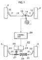
- Figure 1 is a schematic drawing showing a plan view of a vehicle including a rear wheel steering system for a vehicle which is an embodiment of the present invention.
- FIG. 2 is a block diagram showing a control unit of a rear wheel steering system which is an embodiment of the present invention and a detection system provided in a vehicle.
- Figure 3 is a flow chart showing an embodiment of the rear wheel steering angle control effected by a control unit of a vehicle rear wheel steering system.
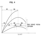
- Figure 4 is a graph showing the relationship between a tire cornering force C.F. and an absolute value of a estimated value of a side slip angle.
- Figure 5 is a flow chart showing another embodiment of the rear wheel steering angle control effected by a control unit of a vehicle rear wheel steering system.
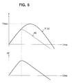
- Figure 6 is a graph showing the relationship between a detected yaw rate and a target yaw rate, and a steering angle of front wheels and time.
- Figure 7 is a flow chart showing a further embodiment of the rear wheel steering angle control effected by a control unit of a vehicle rear wheel steering system.
- Figure 8 is a graph showing the relationship between a limit value, a lateral acceleration GL and a road friction coefficient.
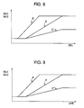
- Figure 9 is a graph showing the relationship between a limit value, an absolute value of the rate of change in steering angle of front wheels and a road surface friction coefficient.
- Figure 10 is a block diagram showing a control unit of a rear wheel steering system which is another embodiment of the present invention and a detection system provided in a vehicle.
- FIG 11 is a flow chart showing a further embodiment of the rear wheel steering angle control effected by the control unit shown in Figure 10.
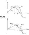
- Figure 12 is a graph showing the relationship between a detected yaw rate and a target yaw rate, and a steering angle of front wheels and time.
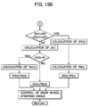
- Figure 13 is a flow chart showing a further embodiment of the rear wheel steering angle control effected by a control unit of a vehicle rear wheel steering system.
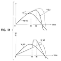
- Figure 14 is a graph showing the relationship between a detected yaw rate and a target yaw rate, and a steering angle of front wheels and time.
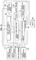
- Figure 15 is a block diagram showing a control unit of a rear wheel steering system which is a further embodiment of the present invention and a detection system provided in a vehicle.
- Figure 16 is a flow chart showing a further embodiment of the rear wheel steering angle control effected by the control unit shown in Figure 15.
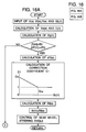
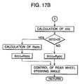
- Figure 17 is a flow chart showing a further embodiment of the rear wheel steering angle control effected by a control unit of a vehicle rear wheel steering system.
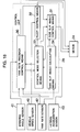
- Figure 18 is a block diagram showing a control unit of a rear wheel steering system which is a further embodiment of the present invention and a detection system provided in a vehicle.
- Figure 19 is a flow chart showing a further embodiment of the rear wheel steering angle control effected by the control unit shown in Figure 18.
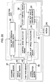
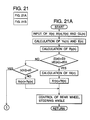
- Figure 20 is a block diagram showing a control unit of a rear wheel steering system which is a further embodiment of the present invention and a detection system provided in a vehicle.
- Figure 21 is a flow chart showing a further embodiment of the rear wheel steering angle control effected by the control unit shown in Figure 20.
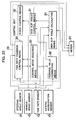
- Figure 22 is a block diagram showing a control unit of a rear wheels steering system which is a further embodiment of the present invention and a detection system provided in a vehicle.
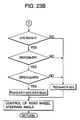
- Figure 23 is a flow chart showing a further embodiment of the rear wheel steering angle control effected by the control unit shown in Figure 22.
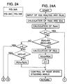
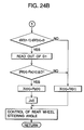
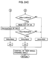
- Figure 24 is a flow chart showing a further embodiment of the rear wheel steering angle control effected by a control unit of a vehicle rear wheel steering system.
- Figure 25 is a flow chart showing an example of a method for determining a value z0.
- Figure 1 is a schematic drawing showing a plan view of a vehicle including a rear wheel steering system which is an embodiment of the present invention.
- the vehicle including the rear wheel steering system which is an embodiment of the present invention comprises a steering wheel 1, front wheel steering system 10 for steering right and left front wheels 2, 2 in accordance with the operation of the steering wheel 1 and a rear wheel steering system 20 for steering right and left rear wheels 3, 3 in response to the steering of the front wheels 2, 2.
- the front steering system 10 is arranged in the widthwise direction of the vehicle and comprises a relay rod 13, the opposite end portions of which are connected with the right and left front wheels 2, 2 via tie rods 11, 11 and knuckle arms 12, 12 and a steering gear mechanism 14 in the form of a rack and pinion for moving the relay rod 13 in the right or left direction in synchronism with the operation of the steering wheel 1.
- the thus constituted front wheel steering system 10 steers the right and left front wheels 2, 2 in the direction corresponding to that in which the steering wheel 1 is turned and by an angle corresponding to the amount of the turning of the steering wheel 1.
- the rear wheels steering system 20 is arranged in the widthwise direction of the vehicle and comprises a relay rod 23, the opposite end portions of which are connected with the right and left rear wheels 3, 3 via tie rods 21, 21 and knuckle arms 22, 22, a motor 24, a steering gear mechanism 27 in the form of a rack and pinion driven by the motor 24 via a speed reducing mechanism 25 and a clutch 26 for moving the relay rod 23 in the right or left direction, a centering spring 28 for biasing the relay rod 23 for locating it at its neutral position and a control unit 29 for controlling the operation of the motor 24 in accordance with driving conditions of the vehicle.
- the thus constituted rear wheel steering system 20 steers the right and left front wheels 3, 3 in the direction corresponding to that of the operation of the steering wheel 1 and by an angle corresponding to the amount by which the steering wheel 1 is turned.
- FIG. 2 is a block diagram showing a control unit 29 of a rear wheel steering system which is an embodiment of the present invention and an associated detection system provided in the vehicle.
- the control unit 29 comprises a yaw rate feedback control means 30, a side slip angle control means 31, a fuzzy control means 32, a control mode selection means 33 and a side slip angle calculating means 34 and receives detection signals from a vehicle speed sensor 40 for detecting the vehicle speed V, a steering angle sensor 41 for detecting the steering angle of the steering wheel 1, namely, the steering angle Xf of the front wheels 2, 2, a yaw rate sensor 42 for detecting the yaw rate Y of the vehicle and a lateral acceleration sensor 43 for detecting the lateral acceleration GL acting on the vehicle.
- the yaw rate feedback control means 30 is constituted so as to calculate a target yaw rate Yo based upon the vehicle speed v input from the vehicle speed sensor 40 and the steering angle Xf of the front wheels 2, 2 input from the steering angle sensor 41, thereby to further calculate the deviation E between the target yaw rate Yo and the detected yaw rate Y input from the yaw rate sensor 42, to calculate a yaw rate feedback value Ry using a I-PD control calculation formula stored therein in advance, and to output the thus calculated yaw rate feedback value Ry to the control mode selection means 33.
- the yaw rate feedback control means 30 is constituted so that when a control effecting signal is input thereto from the control mode selection means 33, it outputs a yaw rate feedback control signal to the motor 24, thereby controlling the steering angle Xr of the rear wheels 3, 3 so as to make it equal to the yaw rate feedback amount Ry.
- the control mode selection means 33 is constituted so as to calculate the rate of change dE in the deviation E between the target yaw rate Yo and the detected yaw rate Y based on the deviation E input from the yaw rate feedback control means 30 so that when the absolute value of the deviation E is greater than a predetermined value E0 and the absolute value of the rate of change dE in the deviation E is greater than a predetermined value dE0, namely, in an extremely sharp turning state, it outputs a control effecting signal to the fuzzy control means 32, that when the absolute value of the deviation E is equal to or smaller than the predetermined value E0 and the absolute value of the rate of change dE in the deviation E is equal to or smaller than the predetermined value dE0 but the estimated absolute value of a side slip angle z calculated by the side slip angle calculating means 34 is greater than a predetermined value z0, namely, in the sharp turning state, it outputs a control effecting signal to the side slip angle control means 31, and that in other states,
- the side slip angle control means 31 is constituted so that when the control effecting signal is input from the control mode selection means 33, it calculates a side slip angle control value Rz in accordance with a calculation formula stored therein in advance and outputs a side slip angle control signal produced based upon the side slip angle control value Rz to the motor 24, thereby to control the steering angle Xr of the rear wheels 3, 3 so that the steering angle Xr(n) of the rear wheels 3, 3 is made equal to the side slip angle control value Rz and that the estimated absolute value of the side slip angle z calculated by the side slip angle calculating means 34 is reduced.
- the fuzzy control means 32 is constituted so that when the control effecting signal is input from the control mode selection means 33, it calculates the rate of change dY in the detected yaw rate Y based upon the detected yaw rate input from the yaw rate sensor 42 and also calculates a fuzzy control value Rf in accordance with a calculation formula stored therein in advance so as to output a fuzzy control signal produced based upon the fuzzy control value Rf to the motor 24, thereby controlling the steering angle Xr of the rear wheels 3, 3 so that the steering angle Xr(n) of the rear wheels 3, 3 is made equal to the fuzzy control value Rf and that the rate of change dY in the detected yaw rate Y is reduced.
- the side slip angle calculating means 34 is constituted so as to estimate the value of the side slip angle z in accordance with the following formula (1) based upon the vehicle speed V detected by the vehicle speed sensor 40, the detected yaw rate Y detected by the yaw rate sensor 42 and the lateral acceleration GL detected by the lateral acceleration sensor 43 and output the estimated value to the control mode selection means 33.
- z(n) 9.8 ⁇ GL(n)/V(n) ⁇ ⁇ Y(n)/57 ⁇ + z(n-1) (1)
- the symbol (n) indicates values in the current control cycle and the symbol (n-1) indicates values in the preceding control cycle.
- Figure 3 is a flow chart showing an embodiment of the steering angle control of rear wheels 3, 3 effected by the thus constituted control unit 29 and Figure 4 is a graph showing the relationship between the tire cornering force C.F. and the estimated absolute side slip angle.
- control unit 29 receives the vehicle speed V(n) detected by the vehicle speed sensor 40, the steering angle Xf(n) of the front wheels 2, 2 detected by the steering angle sensor 41, the detected yaw rate Y(n) detected by the yaw rate sensor 42 and the lateral acceleration GL(n) detected by the lateral acceleration sensor 43.
- the yaw rate feedback control means 30 calculates a target yaw rate Yo(n) for the current control cycle based upon the vehicle speed V(n) input from the vehicle speed sensor 40 and the steering angle Xf(n) of the front wheels 2, 2 input from the steering angle sensor 41 in accordance with the following formula (2).
- Yo(n) V(n)/ ⁇ 1 + A ⁇ V(n)2 ⁇ Xf(n)/L (2)
- A is a stability factor and L is the wheel base.
- the yaw rate feedback control means 30 calculates the deviation E(n) between the thus calculated target yaw rate Yo(n) and the detected yaw rate Y(n) input from the yaw rate sensor 42 in accordance with the following formula (3).
- E(n) Yo(n) - Y(n) (3)
- the yaw rate feedback control means 30 calculates a yaw rate feedback control value Ry(n) for the current control cycle in accordance with the following formula (4).
- Ry(n) Ry(n-1) - [KI ⁇ E(n) - FP ⁇ Y(n) - Y(n-1) ⁇ -FD ⁇ Y(n) - 2 ⁇ Y(n-1) + Y(n-2)] (4)
- KI is a integration constant
- FP is a proportion constant
- FD is a differentiation constant
- Ry(n-1) is the yaw rate feedback control amount in the preceding control cycle
- Y(n-1) is the detected yaw rate in the preceding control cycle
- Y(n-2) is the detected yaw rate in the control cycle before last.
- the thus calculated yaw rate feedback control amount Ry(n) and deviation E(n) are output to the control mode selection means 33.
- the control mode selection means 33 calculates the rate of change dE(n) in the deviation E(n) and judges whether or not the absolute value of the deviation E(n) is greater than a predetermined value E0 and the absolute value of the rate of change dE(n) in the deviation E(n) is greater than a predetermined value dE0.
- the control mode selection means 33 outputs a control effecting signal to the fuzzy control means 32 for controlling the steering angle Xr(n) of the rear wheels 3, 3 based on the fuzzy control calculation.
- the fuzzy control means 32 When the fuzzy control means 32 receives the control effecting signal from the control mode selection means 33, it calculates the rate of change dY(n) in the detected yaw rate Y(n) based upon the detected yaw rate input from the yaw rate sensor 42 and further calculates a fuzzy control value Rf(n) based on a membership function which is experimentally determined so as to reduce the absolute value of the rate of change in the detected yaw rate Y(n) and which depends on the deviation E(n) and the rate of change dE(n) in accordance with the following formula (5).
- Rf(n) f(E(n), dE(n)) (5)
- the fuzzy control means 32 outputs a fuzzy control signal to the motor 24, thereby controlling the steering angle Xr(n) of the rear wheels 3, 3 so that the steering angle Xr(n) of the rear wheels 3, 3 is made equal to the fuzzy control value Rf(n) and the absolute value of the rate of change in the detected yaw rate Y(n) is reduced.
- the control mode selection means 33 judges whether or not the absolute value of the estimated value z(n) of the side slip angle input from the side slip angle calculating means 34 is greater than a predetermined value z0.
- the rear wheels 3, 3 will be steered in the reverse phase with respect to that of the steering angle Xf(n) of the front wheels 2, 2, namely, in the opposite direction to that of the front wheels 2, 2 with respect to the longitudinal center line of the vehicle, whereby there is some risk of the driving stability being lowered.
- the control mode selection means 33 outputs a control effecting signal to the side slip angle control means 31, thereby to cause the side slip angle control means 31 to control the steering angle Xr(n) of the rear wheels 3, 3.
- the side slip angle control means 31 When the side slip angle control means 31 receives the control effecting signal from the control mode selection means 33, it calculates the side slip angle control value Rz(n) in accordance with the following formula (6) and outputs a side slip angle control signal to the motor 24 so as to make the steering angle Xr(n) of the rear wheels 3, 3 become equal to the side slip angle control value Rz(n), thereby to reduce the absolute value of the estimated value z(n) of the side slip angle.
- Rz(n) k1 ⁇ z(n) (6)
- k1 is a control constant and positive. Therefore, the side slip angle control value Rz(n) increases with the estimated value z(n) of the side slip angle and, as a result, since the greater the estimated value z(n) of the side slip angle is, the more the rear wheels 3, 3 are steered in the same phase as that of the front wheels 2, 2, it is possible, in the state where the turning radius is great and the yaw rate Y(n) is low, to prevent the rear wheels 3, 3 from being steered in the reverse phase with respect to that of the front wheels 2, 2 and to reliably prevent the driving stability from being lowered.
- the control mode selection means 33 outputs a control effecting signal to the yaw rate feedback control means 30.
- the yaw rate feedback control means 30 When the yaw rate feedback control means 30 receives the control effecting signal from the control mode selection means 33, it outputs a yaw rate feedback control signal to the motor 24, thereby controlling the steering angle Xr(n) of the rear wheels 3, 3 for making it become equal to the yaw rate feedback control value Ry(n).
- the rear wheels 3, 3 are steered by the yaw rate feedback control means 30 in the stable driving state corresponding to the area S1 so as to make the detected yaw rate Y(n) become equal to the target yaw rate Yo(n) determined based upon the steering angle of the steering wheel 1, it is possible to steer the rear wheels 3, 3 in a desired manner.
- the rear wheels 3, 3 are steered by the side slip angle control means 31 in the state where the estimated absolute value z(n) of the side slip angle is greater than the predetermined value z0 and the vehicle is being sharply turned and subjected to a large lateral acceleration GL(n), in such a manner that the greater the estimated absolute value z(n) of the side slip angle is, the more the rear wheels 3, 3 are steered in the same phase as that of the front wheels 2, 2, namely, in the same direction as that of the front wheels 2, 2 with respect to the longitudinal center line of the vehicle, it is possible to prevent the rear wheels 3, 3 from being steered in the reverse phase with respect to that of the front wheels 2, 2 by the yaw rate feedback control means 30 and to prevent the driving stability from being lowered.
- Figure 5 is a flow chart showing another embodiment of the steering angle control of the rear wheels effected by the control unit shown in Figure 2.
- the control mode selection means 33 immediately causes the yaw rate feedback control means 30 to start controlling the steering angle Xr(n) of the rear wheels 3, 3 for ensuring that the control means for controlling the steering angle Xr(n) of the rear wheels 3, 3 can be smoothly switched from the side slip angle control means 31 or the fuzzy control means 32 to the yaw rate feedback control means 30.
- the control mode selection means 33 judges that the steering angle Xr(n) of the rear wheels 3, 3 should be controlled by the side slip angle control means 31 or the fuzzy control means 32, it further judges whether or not the absolute value of the detected yaw rate Y(n) in the current control cycle is smaller than the absolute value of the detected yaw rate Y(n-1) in the preceding control cycle and whether or not the sign of the rate of change in the steering angle of the steering wheel 1 has changed and causes the side slip angle control means 31 or the fuzzy control means 32 to control the steering angle Xr(n) of the rear wheels 3, 3 when the result is NO, whereas it causes the yaw rate feedback control means 30 to control the steering angle Xr(n) of the rear wheels 3, 3 when the result is YES.
- the control mode selection means 33 further judges whether or not the yaw rate feedback control will be started in a short time without outputting a control effecting signal to the fuzzy control means 32. For this purpose, the control mode selection means 33 judges whether or not the absolute value of the detected yaw rate Y(n) in t he current control cycle is smaller than the absolute value of the detected yaw rate Y(n-1) in the preceding control cycle and whether or not the sign of the rate of change in the steering angle of the steering wheel 1 has changed, namely, whether the absolute value of the steering angle Xf(n) of the front wheels 2, 2 in the current control cycle is smaller than the absolute value of the steering angle Xf(n-1) of the front wheels 2, 2 in the preceding control cycle.
- the control mode selection means 33 outputs a control effecting signal to the yaw rate feedback control means 30 so that the steering angle Xr(n) of the rear wheels 3, 3 is controlled by the yaw rate feedback control means 30.
- the control mode selection means 33 outputs a control effecting signal to the fuzzy control means 32.
- the fuzzy control means 32 When the fuzzy control means 32 receives the control effecting signal from the control mode selection means 33, it calculates the rate of change dY(n) in the detected yaw rate Y(n) based upon the detected yaw rate input from the yaw rate sensor 42 and further calculates a fuzzy control value Rf(n) based on a membership function which is experimentally determined so as to reduce the absolute value of the rate of change dY(n) in the detected yaw rate Y(n) and which depends upon the deviation E(n) and the rate of change dE(n) in accordance with the formula (5).
- the fuzzy control means 32 outputs a fuzzy control signal to the motor 24, thereby controlling the steering angle Xr(n) of the rear wheels 3, 3 so that the steering angle Xr(n) of the rear wheels 3, 3 is made equal to the fuzzy control value Rf(n) and the rate of change in the detected yaw rate Y(n) is reduced.
- the control mode selection means 33 judges whether or not the absolute value of the estimated value z(n) of the side slip angle input from the side slip angle calculating means 34 is greater than a predetermined value z0.
- the control mode selection means 33 further judges whether or not the yaw rate feedback control will be effected in a short time without outputting a control effecting signal to the side slip angle control means 31. For this purpose, the control mode selection means 33 judges whether or not the absolute value of the detected yaw rate Y(n) in the current control cycle is smaller than the absolute value of the detected yaw rate Y(n-1) in the preceding control cycle and whether or not the sign of the rate of change in the steering angle of the steering wheel 1 has changed, namely, whether the absolute value of the steering angle Xf(n) of the front wheels 2, 2 in the current control cycle is smaller than the absolute value of the steering angle Xf(n-1) of the front wheels 2, 2 in the preceding control cycle.
- the control mode selection means 33 outputs a control effecting signal to the yaw rate feedback control means 30 so that the steering angle Xr(n) of the rear wheels 3, 3 is controlled by the yaw rate feedback control means 30.
- the control mode selection means 33 outputs a control effecting signal to the side slip angle control means 31.
- the side slip angle control means 31 When the side slip angle control means 31 receives the control effecting signal from the control mode selection means 33, similarly to the previous embodiment, it calculates the side slip angle control value Rz(n) in accordance with the formula (6) and outputs a side slip angle control signal to the motor 24 so that the steering angle Xr(n) of the rear wheels 3, 3 is made equal to the side slip angle control value Rz(n) and the estimation value of the side slip angle z(n) is reduced. Therefore, in the state where the turning radius of the vehicle is large and the yaw rate Y(n) is low, it is possible to prevent the rear wheels 3, 3 from being steered in the reverse phase with respect to that of the front wheels 2, 2 and reliably prevent the driving stability from being lowered.
- the control mode selection means 33 outputs a control effecting signal to the yaw rate feedback control means 30.
- the yaw rate feedback control means 30 When the yaw rate feedback control means 30 receives the control effecting signal from the control mode selection means 33, it outputs a yaw rate feedback control signal to the motor 24, thereby controlling the steering angle Xr(n) of the rear wheels 3, 3 to make it equal to the yaw rate feedback control value Ry(n).
- the rear wheels 3, 3 are steered by the yaw rate feedback control means 30 in the stable driving state corresponding to the area S1 so as to make the detected yaw rate Y(n) become equal to the target yaw rate Yo(n) determined based upon the steering angle of the steering wheel 1, it is possible to steer the rear wheels 3, 3 in a desired manner.
- the rear wheels 3, 3 are steered by the side slip angle control means 31 in the state where the estimated absolute value z(n) of the side slip angle is greater than the predetermined value z0 and the vehicle is being sharply turned and subjected to a large lateral acceleration GL(n), in such a manner that the greater the estimated absolute value z(n) of the side slip angle is, the more the rear wheels 3, 3 are steered in the same phase as that of the front wheels 2, 2, namely, in the same direction as that of the front wheels 2, 2 with respect to the longitudinal center line of the vehicle, it is possible to prevent the rear wheels 3, 3 from being steered in the reverse phase with respect to that of the front wheels 2, 2 by the yaw rate feedback control means 30 and to prevent the driving stability from being lowered.
- the control mode selection means 33 causes the yaw rate feedback control means 30 to start controlling the steering angle Xr(n) of the rear wheels 3, 3 based on the actually detected value without outputting a control effecting signal to the fuzzy control means 32 or the side slip angle control means 31, it is possible to improve the driving stability and prevent the steering angle Xr(n) of the rear wheels 3, 3 from being suddenly changed when the control means for controlling the steering angle Xr(n) of the rear wheels 3, 3 is changed from the fuzzy control means 32 or the side slip angle control means 31 to the yaw rate feedback control means 30, thereby to prevent the driving stability from being lowered on changing the control means.
- Figure 7 is a flow chart showing a further embodiment of the steering angle control of rear wheels effected by the control unit of the rear wheel steering system.
- the embodiment shown in Figure 7 prevents the steering angle Xr(n) of the rear wheels 3, 3 from being greatly changed when the control means for controlling the steering angle Xr(n) of the rear wheels 3, 3 is changed.
- the control mode selection means 33 is constituted so that when it changes the control means for controlling the steering angle Xr(n) of the rear wheels 3, 3 from the yaw rate feedback control means 30 to the fuzzy control means 32, from the side slip angle control means 31 to the fuzzy control means 32, from the side slip angle control means 31 to the yaw rate feedback control means 30, from the fuzzy control means 32 to the yaw rate feedback control means 30, or from the fuzzy control means 32 to the side slip angle control means 31, it outputs a first control signal together with a control effecting signal to the control means which is to control the steering angle Xr(n) of the rear wheels 3, 3 and that, on the other hand, when the control mode selection means 33 changes the control means for controlling the steering angle Xr(n) of the rear wheels 3, 3 from the yaw rate feedback control means 30 to the side slip angle control means 31, it outputs a second control signal together with a control effecting signal to the side slip angle control means 31.
- the yaw rate feedback control means 30 is constituted so that when it receives only a control effecting signal from the control mode selection means 33, it produces the yaw rate feedback control signal and outputs it to the motor 24 so that the steering angle Xr(n) of the rear wheels 3, 3 can be controlled so as to become equal to the yaw rate feedback control value Ry(n) and that, on the other hand, when it receives the first control signal together with the control effecting signal, it judges whether or not the absolute value of the difference between the steering angle Xr(n) calculated in the current control cycle, namely, the yaw rate feedback control value Ry(n), and the steering angle Xr(n-1) in the preceding control cycle is greater than a first limit value XrL1(n), in other words, whether or not the amount of change in the steering angle Xr of the rear wheels 3, 3 between the preceding control cycle and the current cycle is greater than the first limit value.
- the yaw rate feedback control means 30 produces the yaw rate feedback control signal and outputs it to the motor 24 so that the steering angle Xr(n) of the rear wheels 3, 3 can be controlled so as to become equal to the yaw rate feedback control value Ry(n) calculated in the current control cycle and, on the contrary, when the absolute value of the difference between the steering angle Xr(n) calculated in the current control cycle and the steering angle Xr(n-1) in the preceding control cycle is greater than the first limit value XrL1(n), the yaw rate feedback control means 30 produces the yaw rate feedback control signal and outputs it to the motor 24 so that the steering angle Xr(n) of the rear wheels 3, 3 can be controlled in such a manner that the amount of change in the steering angle Xr
- the side slip angle control means 31 is constituted so that when it receives only a control effecting signal from the control mode selection means 33, it produces the side slip angle control signal and outputs it to the motor 24 so that the steering angle Xr(n) of the rear wheels 3, 3 can be controlled so as to become equal to the side slip angle control value Rz(n) calculated based upon the formula (6) stored therein and that, on the other hand, when it receives the first control signal together with the control effecting signal, it judges whether or not the absolute value of the difference between the steering angle Xr(n) calculated in the current control cycle, namely, the side slip angle control value Rz(n), and the steering angle Xr(n-1) in the preceding control cycle is greater than a first limit value XrL1(n), in other words, whether or not the amount of change in the steering angle Xr of the rear wheels between the preceding control cycle and the current cycle is greater than the first limit value.
- the side slip angle control means 31 When the absolute value of the difference between the steering angle Xr(n) calculated in the current control cycle and the steering angle Xr(n-1) in the preceding control cycle is not greater than the first limit value XrL1(n), the side slip angle control means 31 produces the side slip angle control signal and outputs it to the motor 24 so that the steering angle Xr(n) of the rear wheels 3, 3 can be controlled so as to become equal to the side slip angle control value Rz(n) calculated in the current control cycle and, on the contrary, when the absolute value of difference between the steering angle Xr(n) calculated in the current control cycle and the steering angle Xr(n-1) in the preceding control cycle is greater than the first limit value XrL1(n), the side slip angle control means 31 produces the side slip angle control signal and outputs it to the motor 24 so that the steering angle Xr(n) of the rear wheels 3, 3 can be controlled in such a manner that the amount of change in the steering angle Xr(n) of the rear wheels
- the side slip angle control means 31 receives a second control signal from the control mode selection means 33, it judges whether or not the absolute value of the difference between the steering angle Xr(n) calculated in the current control cycle and the steering angle Xr(n-1) in the preceding control cycle is greater than a second limit value XrL2(n) which is smaller than the first limit value XrL1(n).
- the side slip angle control means 31 judges that the absolute value of the difference between the steering angle Xr(n) calculated in the current control cycle and the steering angle Xr(n-1) in the preceding control cycle is not greater than a second limit value XrL2(n), it produces the side slip angle control signal and outputs it to the motor 24 so that the steering angle Xr(n) of the rear wheels 3, 3 can be controlled so as to become equal to the side slip angle control value Rz(n) calculated in the current control cycle and, on the contrary, when the absolute value of the difference between the steering angle Xr(n) calculated in the current control cycle and the steering angle Xr(n-1) in the preceding control cycle is greater than a second limit value XrL2(n), the side slip angle control means 31 produces the side slip angle control signal and outputs it to the motor 24 so that the steering angle Xr(n) of the rear wheels 3, 3 can be controlled in such a manner that the amount of change in the steering angle Xr(n) of the rear wheels 3, 3
- the fuzzy control means 32 is constituted so that when it receives only a control effecting signal from the control mode selection means 33, it produces a fuzzy control signal and outputs it to the motor 24 so that the steering angle Xr(n) of the rear wheels 3, 3 can be controlled so as to become equal to the fuzzy control value Rf(n) calculated in accordance with the formula (5) and that, on the other hand, when it receives the first control signal together with the control effecting signal, it judges whether or not the absolute value of the difference between the steering angle Xr(n) calculated in the current control cycle, namely, the fuzzy control value Rf(n), and the steering angle Xr(n-1) in the preceding control cycle is greater than a first limit value XrL1(n), in other words, whether or not the amount of change in the steering angle Xr of the rear wheels between the preceding control cycle and the current cycle is greater than the first limit value.
- the fuzzy control means 32 When the absolute value of the difference between the steering angle Xr(n) calculated in the current control cycle and the steering angle Xr(n-1) in the preceding control cycle is not greater than a first limit value XrL1(n), the fuzzy control means 32 produces the fuzzy control signal and outputs it to the motor 24 so that the steering angle Xr(n) of the rear wheels 3, 3 can be controlled so as to become equal to the fuzzy control value Rf(n) calculated in the current control cycle and, on the contrary, when the absolute value of the difference between the steering angle Xr(n) calculated in the current control cycle and the steering angle Xr(n-1) in the preceding control cycle is greater than the first limit value XrL1(n), the fuzzy control means 32 produces the fuzzy control signal and outputs it to the motor 24 so that the steering angle Xr(n) of the rear wheels 3, 3 can be controlled in such a manner that the amount of change in the steering angle Xr(n) of the rear wheels 3, 3 between the current control cycle and the preced
- the side slip angle calculating means 34 is constituted, similarly to the previous embodiment, so as to estimate the value z(n) of the side slip angle based upon the vehicle speed V(n) input from the vehicle speed sensor 40, the detected yaw rate Y(n) input from the yaw rate sensor 42 and the lateral acceleration GL(n) input from the lateral acceleration sensor 43 in accordance with the formula (1) and output the estimated value z(n) to the side slip angle control means 31.
- Figure 8 is a graph showing the relationship between the limit value, the lateral acceleration GL and the road surface friction coefficient
- Figure 9 is a graph showing the relationship between the limit value, the absolute value of the rate of change in steering angle of the front wheels 2, 2 and a road surface friction coefficient.
- the curve A shows the relationship between the first limit value XrL1(n) and the lateral acceleration GL(n) in the case where the vehicle is being driven on a road with a high road surface friction coefficient
- the curve B shows the relationship between the first limit value XrL1(n) and the lateral acceleration GL(n) in the case where the vehicle is being driven on a road with a low road surface friction coefficient is low
- the curve C shows the relationship between the second limit value XrL2(n) and the lateral acceleration GL(n) in the case where the vehicle is being driven on a road with a high road surface friction coefficient and corresponds to the curve A.
- the first limit value XrL1(n) and the second limit value XrL2(n) increase as the absolute value of the lateral acceleration GL(n) becomes greater, and as the road surface friction coefficient becomes lower, they increase within the range where the absolute value of the lateral acceleration GL(n) is low.
- the reason why the first limit value XrL1(n) is made to increase with increasing the absolute value of the lateral acceleration GL(n) is that a large absolute value of the lateral acceleration GL(n) means that the driving condition is probably unstable and, therefore, driving stability should be emphasized over riding comfort.
- the reason why the first limit value XrL1(n) is made to increase with decreasing the road surface friction coefficient within the range where the absolute value of the lateral acceleration GL(n) is low is that when the vehicle is being driven on a road with a low road surface friction coefficient, the driving condition is probably unstable, even though the absolute value of the lateral acceleration GL(n) is low, and, therefore, driving stability should be emphasized over riding comfort. Further, the reason why the second limit value XrL2(n) is set lower than the first limit value XrL1(n) is that the driver tends to feel uncomfortable particularly when the control means for controlling the steering angle Xr(n) of the rear wheels 3, 3 is changed from the yaw rate feedback control means 30 to the side slip angle control means 31.
- the curve "a” shows the relationship between the first limit value XrL1(n) and the absolute value of the rate of change dXf in the steering angle Xf of the front wheels 2, 2 in the case where the vehicle is being driven on a road with a high road surface friction coefficient
- the curve "b” shows the relationship between the first limit value XrL1(n) and the absolute value of the rate of change dXf(n) in the steering angle Xf(n) of the front wheels 2, 2 in the case where the vehicle is being driven on a road with a low road surface friction coefficient.
- the curve "c" shows the relationship between the second limit value XrL2(n) and the absolute value of the rate of change dXf(n) in the steering angle Xf(n) of the front wheels 2, 2 in the case where the vehicle is being driven on a road with a high road surface friction coefficient and corresponds to the curve "a".
- the first limit value XrL1(n) and the second limit value XrL2(n) increase as the absolute value of the rate of change dXf(n) in the steering angle Xf(n) of the front wheels 2, 2 becomes greater, and as the road surface friction coefficient becomes lower, they increase within the range where the absolute value of the rate of change dXf(n) in the steering angle Xf(n) of the front wheels 2, 2 is small.
- the reason why the first limit value XrL1(n) is made to increase as the absolute value of the rate of change dXf(n) in the steering angle Xf(n) of the front wheels 2, 2 becomes greater is that a large absolute value of the rate of change dXf(n) in the steering angle Xf(n) of the front wheels 2, 2 means that the driving condition is probably unstable, and, therefore, driving stability should be emphasized over riding comfort.
- the reason why the first limit value XrL1(n) is made to increase with decreasing the road surface friction coefficient within the range where the absolute value of the rate of change dXf(n) in the steering angle Xf(n) of the front wheels 2, 2 is small is that when the vehicle is being driven on a road with a low road surface friction coefficient, the driving condition is probably unstable, even though the absolute value of the rate dXf(n) of change in the steering angle Xf(n) of the front wheels 2, 2 is small, and, therefore, driving stability should be emphasized over riding comfort.
- the reason why the second limit value XrL2(n) is set lower than the first limit value XrL1(n) is that the driver tends to feel uncomfortable particularly when the control means for controlling the steering angle Xr(n) of the rear wheels 3, 3 is changed from the yaw rate feedback control means 30 to the side slip angle control means 31.
- control unit 29 first receives the vehicle speed V(n) detected by the vehicle speed sensor 40, the steering angle Xf(n) of the front wheels 2, 2 detected by the steering angle sensor 41, the detected yaw rate Y(n) detected by the yaw rate sensor 42 and the lateral acceleration GL(n) detected by the lateral acceleration sensor 43.
- the yaw rate feedback control means 30 calculates the target yaw rate Y0(n) based upon the vehicle speed V(n) input from the vehicle speed sensor 40 and the steering angle Xf(n) of the front wheels 2, 2 input from the steering angle sensor 41 and calculates the deviation E(n) between the thus calculated target yaw rate Yo(n) and the detected yaw rate Y(n) input from the yaw rate sensor 42. Further, the yaw rate feedback control means 30 calculates the yaw rate feedback value Ry(n) in accordance with the I-PD calculation formula.
- the thus calculated yaw rate feedback value Ry(n) and deviation E(n) are output to the control mode selection means 33.
- the control mode selection means 33 calculates the rate of change dE(n) in the deviation E(n) and judges whether or not the absolute value of the deviation E(n) is greater than the predetermined value E0 and the absolute value of the rate of change dE(n) in the deviation E(n) is greater than the predetermined value dE0.
- the control mode selection means 33 judges that the steering angle Xr(n) of the rear wheels 3, 3 should be controlled by the fuzzy control means 32 and produces a control effecting signal. Then, the control mode selection means 33 further judges whether or not the steering angle Xr(n-1) of the rear wheels 3, 3 was controlled by the fuzzy control means 32 in the preceding control cycle.
- the control mode selection means 33 outputs only the control effecting signal to the fuzzy control means 32.
- control mode selection means 33 judges that the steering angle Xr(n-1) of the rear wheels 3, 3 was controlled by the yaw rate feedback control means 30 or the side slip angle control means 31 in the preceding control cycle, it outputs a first control signal to the fuzzy control means 32 in addition to the control effecting signal.
- the fuzzy control means 32 When the fuzzy control means 32 receives the control effecting signal from the control mode selection means 33, similarly to the previous embodiments, it calculates the rate of change dY(n) in the detected yaw rate Y(n) based upon the detected yaw rate input from the yaw rate sensor 42 and further calculates a fuzzy control value Rf(n) based on a membership function which is experimentally determined so as to reduce the absolute value of the rate of change in the detected yaw rate Y(n) and which depends upon the deviation E(n) and the rate of change dE(n) in accordance with the formula (5).
- the fuzzy control means 32 produces the fuzzy control signal and outputs it to the motor 24 so that the steering angle Xr(n) of the rear wheels 3, 3 can be controlled so as to become equal to the fuzzy control value Rf(n).
- the fuzzy control means 32 receives the first control signal together with the control effecting signal from the control mode selection means 33, it judges whether or not the absolute value of the difference between the fuzzy control value Rf(n) calculated in the current control cycle and the steering angle Xr(n-1) of the rear wheels 3, 3 in the preceding control cycle is greater than the first limit value XrL1(n).
- the fuzzy control means 32 produces the fuzzy control signal and outputs it to the motor 24 so that the steering angle Xr(n) of the rear wheels 3, 3 can be controlled so as to become equal to the fuzzy control value Rf(n).
- the fuzzy control means 32 when the result of the judgment is YES, namely, when the absolute value of the difference between the fuzzy control value Rf(n) and the steering angle Xr(n-1) of the rear wheels 3, 3 in the preceding control cycle is greater than the first limit value XrL1(n), if the fuzzy control value Rf(n) is greater than the steering angle Xr(n-1) of the rear wheels 3, 3 in the preceding control cycle, the fuzzy control means 32 produces the fuzzy control signal and outputs it to the motor 24 so that the steering angle Xr(n) of the rear wheels 3, 3 is controlled so as to become equal to ⁇ Xr(n-1) + XrL1(n) ⁇ and if the fuzzy control value Rf(n) is not greater than the steering angle Xr(n-1) of the rear wheels 3, 3 in the preceding control cycle, the fuzzy control means 32 produces the fuzzy control signal and outputs it to the motor 24 so that the steering angle Xr(n) of the rear wheels 3, 3 is controlled so as to become equal to
- the control mode selection means 33 stores maps corresponding to the graphs shown in Figures 8 and 9 and determines the first limit value XrL1(n) from the stored map based on the vehicle speed V(n), the steering angle Xf(n) of the front wheels 2, 2 and the lateral acceleration GL(n).
- the control mode selection means 33 judges whether or not the absolute value of the estimated value z(n) of the side slip angle input from the side slip angle calculating means 34 is greater than a predetermined value z0.
- the control mode selection means 33 judges that the steering angle Xr(n) of the rear wheels 3, 3 should be controlled by the side slip angle control means 31 and produces a control effecting signal. Then, the control mode selection means 33 further judges whether or not the steering angle Xr(n-1) of the rear wheels 3, 3 was controlled by the side slip angle control means 31 in the preceding control cycle.
- the control mode selection means 33 judges that the steering angle Xr(n-1) of the rear wheels 3, 3 was controlled by the side slip angle control means 31 in the preceding control cycle, the control mode selection means 33 outputs only the control effecting signal to the side slip angle control means 31.
- control mode selection means 33 further judges whether or not the steering angle Xr(n-1) of the rear wheels 3, 3 was controlled by the yaw rate feedback control means 30 in the preceding control cycle.
- control mode selection means 33 judges that the steering angle Xr(n-1) of the rear wheels 3, 3 was controlled by the fuzzy control means 32 in the preceding control cycle, it outputs the first control signal together with the control effecting signal to the side slip angle control means 31.
- control mode selection means 33 judges that the steering angle Xr(n-1) of the rear wheels 3, 3 was controlled by the yaw rate feedback control means 30 in the preceding control cycle, it outputs the second control signal together with the control effecting signal to the side slip angle control means 31.
- the side slip angle control means 31 When the side slip angle control means 31 receives the control effecting signal from the control mode selection means 33, similarly to the embodiment shown in Figure 3, it calculates the side slip angle control value Rz(n) in accordance with the formula (6). Then, when only the control effecting signal is input, the side slip angle control means 31 produces the side slip angle control signal and outputs it to the motor 24 so that the steering angle Xr(n) of the rear wheels 3, 3 is made equal to the side slip angle control value Rz(n). Therefore, in the state where the turning radius of the vehicle is large and the yaw rate Y(n) is low, it is possible to prevent the rear wheels 3, 3 from being steered in the reverse phase with respect to that of the front wheels 2, 2 and reliably prevent the driving stability from being lowered.
- the side slip angle control means 31 receives the first control signal together with the control effecting signal, it further judges whether or not the absolute value of the difference between the side slip angle control value Rz(n) calculated in the current control cycle and the steering angle Xr(n-1) of the rear wheels 3, 3 in the preceding control cycle is greater than the first limit value XrL1(n).
- the side slip angle control means 31 When the absolute value of the difference between the side slip angle control value Rz(n) calculated in the current control cycle and the steering angle Xr(n-1) of the rear wheels 3, 3 in the preceding control cycle is not greater than the first limit value XrL1(n), the side slip angle control means 31 produces the side slip angle control signal and outputs it to the motor 24 so that the steering angle Xr(n) of the rear wheels 3, 3 can be controlled so as to become equal to the side slip angle control value Rz(n).
- the side slip angle control means 31 produces the side slip angle control signal and outputs it to the motor 24 so that the steering angle Xr(n) of the rear wheels 3, 3 is controlled so as to become equal to ⁇ Xr(n-1) + XrL1(n) ⁇ and if the side slip angle control value Rz(n) calculated in the current cycle is not greater than the steering angle Xr(n-1) of the rear wheels 3, 3 in the preceding control cycle, the side slip angle control means 31 produces the side slip angle control signal and outputs it to the motor 24 so that the steering angle Xr(n) of
- the side slip angle control means 31 receives the second control signal together with the control effecting signal, it further judges whether or not the absolute value of the difference between the side slip angle control value Rz(n) calculated in the current control cycle and the steering angle Xr(n-1) of the rear wheels 3, 3 in the preceding control cycle is greater than the second limit value XrL2(n).
- the side slip angle control means 31 When the absolute value of the difference between the side slip angle control value Rz(n) calculated in the current control cycle and the steering angle Xr(n-1) of the rear wheels 3, 3 in the preceding control cycle is not greater than the second limit value XrL2(n), the side slip angle control means 31 produces the side slip control signal and outputs it to the motor 24 so that the steering angle Xr(n) of the rear wheels 3, 3 can be controlled so as to become equal to the side slip angle control value Rz(n).
- the side slip angle control means 31 produces the side slip angle control signal and outputs it to the motor 24 so that the steering angle Xr(n) of the rear wheels 3, 3 is controlled so as to become equal to ⁇ Xr(n-1) + XrL2(n) ⁇ and if the side slip angle control value Rz(n) calculated in the current cycle is not greater than the steering angle Xr(n-1) of the rear wheels 3, 3 in the preceding control cycle, the side slip angle control means 31 produces the side slip angle control signal and outputs it to the motor 24 so that the steering angle Xr(n) of
- the control mode selection means 33 stores maps corresponding to the graphs shown in Figures 8 and 9 and determines the second limit value XrL2(n) from the stored maps based upon the vehicle speed V(n), the steering angle Xf(n) of the front wheels 2, 2 and the lateral acceleration GL(n).
- control mode selection means 33 produces a control effecting signal and further judges whether or not the steering angle Xr(n) of the rear wheels 3, 3 was controlled by the yaw rate feedback control means 30 in the preceding control cycle.
- control mode selection means 33 outputs only the control effecting signal to the yaw rate feedback control means 30.
- control mode selection means 33 judges that the steering angle Xr(n) of the rear wheels 3, 3 was controlled by the side slip angle control means 31 or the fuzzy control means 32 in the preceding control cycle, it outputs a first control signal together with the control effecting signal to the yaw rate feedback control means 30.
- the yaw rate feedback control means 30 When the yaw rate feedback control means 30 receives only the control effecting signal from the control mode selection means 33, it produces the yaw rate feedback control signal and outputs it to the motor 24 so that the steering angle Xr(n) of the rear wheels 3, 3 can be controlled so as to become equal to the yaw rate feedback control value Ry(n).
- the yaw rate feedback control means 30 receives the first control signal together with the control effecting signal, it further judges whether or not the absolute value of the difference between the yaw rate feedback control value Ry(n) calculated in the current control cycle and the steering angle Xr(n-1) of the rear wheels 3, 3 in the preceding control cycle is greater than the first limit value XrL1(n).
- the yaw rate feedback control means 30 When the absolute value of the difference between the yaw rate feedback control value Ry(n) calculated in the current control cycle and the steering angle Xr(n-1) of the rear wheels 3, 3 in the preceding control cycle is not greater than the first limit value XrL1(n), the yaw rate feedback control means 30 produces the yaw rate feedback control signal and outputs it to the motor 24 so that the steering angle Xr(n) of the rear wheels 3, 3 can be controlled so as to become equal to the yaw rate feedback control value Ry(n).
- the yaw rate feedback control means 30 produces the yaw rate feedback control signal and outputs it to the motor 24 so that the steering angle Xr(n) of the rear wheels 3, 3 is controlled so as to become equal to ⁇ Xr(n-1) + XrL1(n) ⁇ and if the yaw rate feedback control value Ry(n) calculated in the current control cycle is not greater than the steering angle Xr(n-1) of the rear wheels 3, 3 in the preceding control cycle, the yaw rate feedback control means 30 produces the yaw rate feedback control signal and outputs it to
- the rear wheels 3, 3 are steered by the yaw rate feedback control means 30 in the stable driving state corresponding to the area S1 so as to make the detected yaw rate Y(n) become equal to the target yaw rate Yo(n) determined based upon the steering angle of the steering wheel 1, it is possible to steer the rear wheels 3, 3 in a desired manner.
- the rear wheels 3, 3 are steered by the side slip angle control means 31 in the state where the estimated absolute value z(n) of the side slip angle is greater than the predetermined value z0 and the vehicle is being sharply turned and subjected to a large lateral acceleration GL(n), in such a manner that the greater the estimated absolute value z(n) of the side slip angle is, the more the rear wheels 3, 3 are steered in the same phase as that of the front wheels 2, 2, namely, in the same direction as that of the front wheels 2, 2 with respect to the longitudinal center line of the vehicle, it is possible to prevent the rear wheels 3, 3 from being steered in the reverse phase with respect to that of the front wheels 2, 2 by the yaw rate feedback control means 30 and to prevent the driving stability from being lowered.
- the control means for controlling the steering angle Xr(n) of the rear wheels 3, 3 is changed from the yaw rate feedback control means 30 to the fuzzy control means 32, from the side slip angle control means 31 to the yaw rate feedback control means 30, from the fuzzy control means 32 to the yaw rate feedback control means 30 or from the fuzzy control means 32 to the side slip angle control means 31, the steering angle Xr(n) of the rear wheels 3, 3 is controlled so that the amount of change in the steering angle Xr of the rear wheels 3, 3 between the preceding control cycle and the current cycle becomes equal to the first limit value XrL1(n), and when the control means for controlling the steering angle Xr(n) of the rear wheels 3, 3 is changed from the yaw rate
- first limit value XrL1(n) and the second limit value XrL2(n) increase under unstable driving conditions in accordance with the maps shown in Figures 8 and 9. Therefore, according to this embodiment, it is possible to prevent the driving stability from being lowered and the driver from feeling uncomfortable.
- Figure 10 is a block diagram showing a control unit of a rear wheels steering system which is another embodiment of the present invention and a detection system provided in a vehicle.
- the control unit 29 comprises a steering angle restricting means 35 in addition to the yaw rate feedback control means 30, the side slip angle control means 31, the fuzzy control means 32, the control mode selection means 33 and the side slip angle calculating means 34, and receives detection signals from the vehicle speed sensor 40 for detecting the vehicle speed V, the steering angle sensor 41 for detecting the steering angle of the steering hand wheel 1, namely, the steering angle Xf of the front wheels 2, 2, the yaw rate sensor 42 for detecting the yaw rate Y of the vehicle and the lateral acceleration sensor 43 for detecting the lateral acceleration GL acting on the vehicle.
- the yaw rate feedback control means 30 is constituted so as to calculate a target yaw rate Yo(n) based on the vehicle speed V(n) input from the vehicle speed sensor 40 and the steering angle Xf(n) of the front wheels 2, 2 input from the steering angle sensor 41, to further calculate the deviation E(n) between the target yaw rate Yo(n) and a detected yaw rate Y(n) input from the yaw rate sensor 42, to calculate the yaw rate feedback value Ry(n) using the I-PD control calculation formula (4) stored therein and to output the thus calculated yaw rate feedback value Ry(n) to the control mode selection means 33. Further, the yaw rate feedback control means 30 is constituted so that when a control effecting signal is input thereto from the control mode selection means 33, it outputs a yaw rate feedback control signal to the steering angle restricting means 35.
- the control mode selection means 33 is constituted the same as that of the embodiment shown in Figure 2.
- the side slip angle control means 31 is constituted so that when the control effecting signal is input thereto from the control mode selection means 33, it calculates a side slip angle control value Rz(n) in accordance with the calculation formula (6) stored therein and outputs a side slip angle control signal to the steering angle restricting means 35.
- the fuzzy control means 32 is constituted so that when the control effecting signal is input from the control mode selection means 33, it calculates the rate of change dY(n) in the detected yaw rate Y(n) input from the yaw rate sensor 42 and also calculates a fuzzy control value Rf(n) in accordance with the calculation formula (5) stored therein when a control effecting signal is input thereto from the control mode selection means 33, thereby to output the fuzzy control signal to the steering angle restricting means 35.
- the side slip angle calculating means 34 is constituted similarly to the previous embodiments so as to estimate the value of the side slip angle z in accordance with the formula (1) and output it to the control mode selection means 33.
- the steering angle restricting means 35 is constituted so that when the absolute value of the deviation E(n) between the target yaw rate Yo(n) and the detected yaw rate Y(n) input from the yaw rate feedback control means 30 is greater than a predetermined value E1 and it judges based on the steering angle Xf(n) of the front wheels 2, 2 that the steering wheel 1 has been turned back and also judges that the absolute value of the detected yaw rate Y(n) is increasing, it outputs a steering angle restriction signal to the motor 24 so as to fix the steering angle Xr(n) of the rear wheels 3, 3 to the steering angle Xr(n-1) in the preceding control cycle, and is further constituted so that when the absolute value of the deviation E(n) is not greater than the predetermined value E1 or even if it is if it judges that the steering wheel 1 has not been turned back, it outputs the yaw rate feedback control signal, the side slip angle control signal or the fuzzy control signal input from the control means selected by the
- Figure 11 is a flow chart showing a further embodiment of the steering angle control of rear wheels 3, 3 effected by the thus constituted control unit 29 and Figure 12 is a graph showing the relationship between the target yaw rate Yo(n) and the detected yaw rate Y(n), and the steering angle Xf(n) of the front wheels 2, 2 and time.
- control unit 29 receives the vehicle speed V(n) detected by the vehicle speed sensor 40, the steering angle Xf(n) of the front wheels 2, 2 detected by the steering angle sensor 41, the detected yaw rate Y(n) detected by the yaw rate sensor 42 and the lateral acceleration GL(n) detected by the lateral acceleration sensor 43.
- the yaw rate feedback control means 30 calculates a target yaw rate Yo(n) in the current control cycle in accordance with the formula (2) and further calculates the deviation E(n) between the thus calculated target yaw rate Yo(n) and the detected yaw rate Y(n) input from the yaw rate sensor 42 in accordance with the formula (3). Further, the yaw rate feedback control means 30 calculates a yaw rate feedback control value Ry(n) in the current control cycle in accordance with the formula (4).
- the steering angle restricting means 35 judges whether or not the absolute value of the deviation E(n) is greater than a predetermined value E1.
- the steering angle restricting means 35 further judges whether or not the absolute value of the steering angle Xf(n) of the front wheels 2, 2 input from the steering angle sensor 41 is smaller than the absolute value of the steering angle Xf(n-1) of the front wheels 2, 2 in the preceding control cycle, namely, whether or not the steering wheel 1 has been turned back.
- the rear wheels 3, 3 will be excessively steered in the same phase as the front wheels 2, 2 as indicated by a dotted line in Figure 12 and, as a result, since the phase of the steering angle Xr(n) of the rear wheels 2, 2 and that of the front wheels 2, 2 are reverse to each other during time period from the time t2 when the sign of the steering angle Xf(n) of the front wheels 2, 2 changes to the time t3 when the sign of the steering angle Xr(n) of the rear wheels 3, 3 changes after the detected yaw rate Y(n) went over its peak value and began
- the steering angle restricting means 35 outputs a steering angle restriction signal to the motor 24 for fixing the steering angle Xr(n) of the rear wheels 3, 3 in the current control cycle to the steering angle Xr(n-1) of the rear wheels 3, 3 input from the yaw rate feedback control means 30, the side slip angle control means 31 or the fuzzy control means 32, whichever is selected by the control mode selection means 33, and stored therein in the preceding control cycle so that the rear wheels 3, 3 can be prevented from being excessively steered in the same direction as the front wheels 2, 2.
- the steering angle Xr(n) of the rear wheels 3, 3 is fixed to be constant from the time t1, as indicated by a solid line in Figure 12.
- the steering angle restricting means 35 does not output the steering angle restriction signal but outputs the yaw rate feedback control signal, the side slip angle control signal or the fuzzy control signal input from the yaw rate feedback control means 30, the side slip angle control means 31 or the fuzzy control means 32 which is selected by the control mode selecting means 33 to the motor 24.
- This state corresponds to the state at the time t4 in Figure 12. Since it should be considered that this shows that the steering angle Xr(n) of the rear wheels 3, 3 will be controlled by the yaw rate feedback control means 30 in a short time, even though the control mode selection means 33 has selected the side slip angle control means 31 or the fuzzy control means 32 and the steering angle restricting means 35 has received the side slip angle control signal or the fuzzy control signal, the control mode selection means 33 causes the yaw rate feedback control means 30 to output the yaw rate feedback control signal and outputs it to the motor for preventing the steering angle Xr(n) of the rear wheels 3, 3 from being suddenly and greatly changed when the yaw rate feedback control is effected, thereby to prevent the driving stability from being lowered.
- the control mode selection means 33 calculates the rate of change dE(n) in the deviation E(n) and judges whether or not the absolute value of the deviation E(n) is greater than a predetermined value E0 which is smaller than the predetermined value E1 and the rate of change dE(n) in the deviation E(n) is greater than a predetermined value dE0 for determining whether the steering angle Xr(n) of the rear wheels 3, 3 should be controlled by the yaw rate feedback control means 30, the side slip angle control means 31 or the fuzzy control means 32.
- the control mode selection means 33 outputs a control effecting signal to the fuzzy control means 32 for controlling the steering angle Xr(n) of the rear wheels 3, 3 based upon fuzzy control.
- the fuzzy control means 32 When the fuzzy control means 32 receives the control effecting signal from the control mode selection means 33, similarly to the embodiment shown in Figure 3, it calculates the rate of change dY(n) in the detected yaw rate Y(n) and further calculates a fuzzy control value Rf(n) based on a membership function which is experimentally determined so as to reduce the absolute value of the rate of change dY(n) in the detected yaw rate Y(n) and which depends upon the deviation E(n) and the rate dE(n) of change in accordance with the formula (5).
- the fuzzy control means 32 outputs a fuzzy control signal to the motor 24, thereby controlling the steering angle Xr(n) of the rear wheels 3, 3 so that the steering angle Xr(n) of the rear wheels 3, 3 becomes equal to the fuzzy control value Rf(n) and the absolute value of the rate of change dY(n) in the detected yaw rate Y(n) is reduced.
- the control mode selection means 33 judges whether or not the absolute value of the estimated value z(n) of the side slip angle input from the side slip angle calculating means 34 is greater than a predetermined value z0.
- the control mode selection means outputs a control effecting signal to the side slip angle control means 31, thereby to cause the side slip angle control means 31 to control the steering angle Xr(n) of the rear wheels 3, 3.
- the side slip angle control means 31 When the side slip angle control means 31 receives the control effecting signal from the control mode selection means 33, similarly to the embodiment shown in Figure 3, it calculates the side slip angle control value Rz(n) in accordance with the formula (6) and outputs a side slip angle control signal to the motor 24 so that the steering angle Xr(n) of the rear wheels 3, 3 becomes equal to the side slip angle control value Rz(n) and the absolute value of the estimated value of the side slip angle z(n) is reduced. Therefore, in the state where the turning radius of the vehicle is large and the yaw rate Y(n) is low, it is possible to prevent the rear wheels 3, 3 from being steered in the reverse phase with respect to that of the front wheels 2, 2 and reliably prevent the driving stability from being lowered.
- the control mode selection means 33 outputs a control effecting signal to the yaw rate feedback control means 30.
- the yaw rate feedback control means 30 When the yaw rate feedback control means 30 receives the control effecting signal from the control mode selection means 33, it outputs a yaw rate feedback control signal to the motor 24, thereby controlling the steering angle Xr(n) of the rear wheels 3, 3 so as to become equal to the yaw rate feedback control value Ry(n) calculated in accordance with the formula (4).
- the rear wheels 3, 3 are steered by the yaw rate feedback control means 30 in the stable driving state corresponding to the area S1 so as to make the detected yaw rate Y(n) become equal to the target yaw rate Yo(n) determined based upon the steering angle of the steering wheel 1, it is possible to steer the rear wheels 3, 3 in a desired manner.
- the rear wheels 3, 3 are steered by the side slip angle control means 31 in the state where the estimated absolute value z(n) of the side slip angle is greater than the predetermined value z0 and the vehicle is being sharply turned and subjected to a large lateral acceleration GL(n), in such a manner that the greater the estimated absolute value z(n) of the side slip angle is, the more the rear wheels 3, 3 are steered in the same phase as that of the front wheels 2, 2, namely, in the same direction as that of the front wheels 2, 2 with respect to the longitudinal center line of the vehicle, it is possible to prevent the rear wheels 3, 3 from being steered in the reverse phase with respect to that of the front wheels 2, 2 by the yaw rate feedback control means 30 and to prevent the driving stability from being lowered.
- the steering wheel 1 is once turned in one direction and the absolute values of the target yaw rate Yo(n) and the detected yaw rate Y(n) begin to increase, the steering wheel 1 is turned back in the other direction, the absolute value of the target yaw rate Yo(n) will begin to decrease but the absolute value of the detected yaw rate Y(n) will continue to increase due to the delay of control so that the absolute value of the deviation E(n) between the target yaw rate Yo(n) and the detected yaw rate Y(n) will be greater than the predetermined value E1 and still be further increasing.
- the rear wheels 3, 3 will be excessively steered in the same phase as that of the front wheels 2, 2 and, as a result, since the phase of the steering angle Xr(n) of the rear wheels 2, 2 and that of the front wheels 2, 2 will be reverse to each other during the time period from the time t2 when the sign of the steering angle Xf(n) of the front wheels 2, 2 changes to the time t3 when the sign of the steering angle Xr(n) of the rear wheels 3, 3 changes after the absolute value of the detected yaw rate Y(n) goes over its peak value and begins
- Figure 13 is a flow chart showing a further embodiment of the steering angle control of rear wheels effected by a control unit of a rear wheels steering system according to the present invention.
- the control unit 29 comprises the yaw rate feedback control means 30, the side slip angle control means 31, the fuzzy control means 32, the control mode selection means 33, the side slip angle calculating means 34 and the steering angle restricting means 35, and receives detection signals from the vehicle speed sensor 40 for detecting the vehicle speed V, the steering angle sensor 41 for detecting the steering angle of the steering hand wheel 1, namely, the steering angle Xf of the front wheels 2, 2, the yaw rate sensor 42 for detecting the yaw rate Y of the vehicle and the lateral acceleration sensor 43 for detecting the lateral acceleration GL applied to the vehicle laterally.
- the yaw rate feedback control means 30, the side slip angle control means 31, the fuzzy control means 32 and the side slip angle calculating means 34 are constituted similarly to the embodiment shown in Figure 10.
- the control mode selection means 33 is constituted similarly to the previous embodiments.
- the steering angle restricting means 35 is constituted so that when it judges based upon the steering angle Xf(n) of the front wheels 2, 2 that the steering wheel 1 has been turned back and also judges that the absolute value of the detected yaw rate Y(n) is increasing, it calculates the rate of change dE(n) in the deviation E(n) based upon the deviation E(n) between the target yaw rate Yo(n) and the detected yaw rate Y(n) input from the yaw rate feedback control means 30 and when it judges that the absolute value of the deviation E(n) is greater than a predetermined value E2 and the absolute value of the rate of change dE(n) in the deviation E(n) is greater than a predetermined value dE1, it outputs a steering angle restriction signal to the motor for restricting the steering angle Xr(n) of the rear wheels 3, 3 to make the amount of the steering of the rear wheels 3, 3 become maximum so as to reduce the absolute value of the detected yaw rate Y(n
- the steering wheel 1 when the absolute value of the detected yaw rate Y(n) is not increasing, when the steering wheel 1 has not been turned back although the absolute value of the detected yaw rate Y(n) is increasing, when the absolute value of the deviation E(n) is not greater than the predetermined value E2 although the absolute value of the detected yaw rate Y(n) is increasing and the steering wheel 1 has been turned back, or when the absolute value of the rate of change dE(n) in the deviation E(n) is not greater than the predetermined value dEl although t he absolute value of the detected yaw rate Y(n) is increasing, the steering wheel 1 has been turned back and the absolute value of the deviation E(n) is greater than the predetermined value E2, if the steering angle restriction signal was not output in the preceding control cycle, the steering angle restricting means 35 outputs to the motor 24 the yaw rate feedback control signal, the side slip angle control signal or the fuzzy control signal input from whichever the control means is selected by the control mode
- control unit 29 receives the vehicle speed V(n) detected by the vehicle speed sensor 40, the steering angle Xf(n) of the front wheels 2, 2 detected by the steering angle sensor 41, the detected yaw rate Y(n) detected by the yaw rate sensor 42 and the lateral acceleration GL(n) detected by the lateral acceleration sensor 43 and the yaw rate feedback control means 30 calculates a target yaw rate Yo(n) in the current control cycle in accordance with the formula (2).
- the yaw rate feedback control means 30 calculates the deviation E(n) between the thus calculated target yaw rate Yo(n) and the detected yaw rate Y(n) input from the yaw rate sensor 42 in accordance with the formula (3) and further calculates a yaw rate feedback control value Ry(n) in the current control cycle in accordance with the formula (4).
- the steering angle restricting means 35 judges whether or not the absolute value of the detected yaw rate Y(n) input from the yaw rate sensor 42 is greater than the detected yaw rate Y(n-1) input in the preceding control cycle, namely, whether or not the absolute value of the detected yaw rate Y(n) is increasing and has not reached its peak value Ymax.
- the steering angle restricting means 35 further judges whether or not the absolute value of the steering angle Xf(n) of the front wheels 2, 2 input from the steering angle sensor 41 is smaller than the absolute value of the steering angle Xf(n-1) of the front wheels 2, 2 input in the preceding control cycle, namely, whether or not the steering wheel 1 has been turned back.
- the steering angle restricting means 35 calculates the rate of change dE(n) in the deviation E(n) and judges whether or not the absolute value of the rate of change dE(n) in the deviation E(n) is greater than the predetermined value dE1.
- Figure 14 is a graph showing the relationship between the target yaw rate Yo(n), the detected yaw rate Y(n), the steering angle Xf(n) of the front wheels 2, 2 and time.
- the aforesaid state corresponds to the state at the time t5 in Figure 14.
- the steering angle Xr(n) of the rear wheels 3, 3 is controlled so as to become equal to the yaw rate feedback control value Ry(n), the side slip angle control value Rz(n) or the fuzzy control value Rf(n) calculated by the yaw rate feedback control means 30, the side slip angle control means 31 or the fuzzy control means 32, whichever is selected by the control mode selection means 33 in accordance with the driving conditions, the steering angle Xr(n) of the rear wheels 3, 3 and the detected yaw rate Y(n) will be changed as indicated by the dot wave in Figure 14 and since the amount of steering of the rear wheels 3, 3 in the same phase as that of the front wheels 2, 2 is relatively small, there will be a considerable risk of oversteering and it will be very difficult to prevent the driving stability from being lowered.
- the steering angle restricting means 35 outputs a steering angle restriction signal to the motor 24 for steering the rear wheels 3, 3 so that the amount of steering of the rear wheels 3, 3 becomes maximum so as to decrease the absolute value of the detected yaw rate Y(n), thereby preventing excessive oversteering.
- the steering angle Xr(n) of the rear wheels 3, 3 is controlled so as to become great suddenly from the time t5 and the detected yaw rate Y(n) is decreased as indicated by the solid wave in Figure 14.
- the steering angle restricting means 35 causes the yaw rate feedback control means 30 to output the yaw rate feedback control signal and outputs it to the motor 24 for preventing the driving stability from being lowered by preventing the steering angle Xr(n) of the rear wheels 3, 3 from being suddenly and greatly changed on starting the yaw rate feedback control so that the steering angle Xr(n) of the rear wheels 3, 3 is controlled so as to become equal to the yaw rate feedback control value Ry(n), even if the side slip angle control means 31 or the fuzzy control means 32 has been selected by the control mode selection means 33 and the side slip angle control signal or the fuzzy control signal has been input.
- the control mode selection means 33 outputs a control effecting signal to the fuzzy control means 32 for controlling the steering angle Xr(n) of the rear wheels 3, 3 based upon the fuzzy control.
- the aforesaid predetermined values are selected such that when the vehicle is making frequent and sharp turns on a road with a low road surface friction coefficient, the vehicle can be prevented from being excessively oversteered by the steering angle restricting means 35, and when the vehicle is making frequent and sharp turns on a road with a medium or higher road surface friction coefficient, the vehicle can be prevented from being oversteered by the fuzzy control means 32.
- the fuzzy control means 32 When the fuzzy control means 32 receives the control effecting signal from the control mode selection means 33, it calculates the rate of change dY(n) in the detected yaw rate Y(n) and further calculates a fuzzy control value Rf(n) based on a membership function which is experimentally determined so as to reduce the absolute value of the rate of change dY(n) in the detected yaw rate Y(n) and which depends upon the deviation E(n) and the rate of change dE(n) in accordance with the formula (5).
- the fuzzy control means 32 outputs a fuzzy control signal to the motor 24, thereby controlling the steering angle Xr(n) of the rear wheels 3, 3 so that the steering angle Xr(n) of the rear wheels 3, 3 becomes equal to the fuzzy control value Rf(n) and the rate of change in the detected yaw rate Y(n) is reduced.
- the control mode selection means 33 judges whether or not the absolute value of the estimated value z(n) of the side slip angle input from the side slip angle calculating means 34 is greater than a predetermined value z0.
- the control mode selection means outputs a control effecting signal to the side slip angle control means 31, thereby to cause the side slip angle control means 31 to control the steering angle Xr(n) of the rear wheels 3, 3.
- the side slip angle control means 31 When the side slip angle control means 31 receives the control effecting signal from the control mode selection means 33, similarly to the embodiment shown in Figure 3, it calculates the side slip angle control value Rz(n) in accordance with the formula (6) and outputs a side slip angle control signal to the motor 24 so that the steering angle Xr(n) of the rear wheels 3, 3 becomes equal to the side slip angle control value Rz(n) and the absolute value of the estimated value of the side slip angle z(n) is reduced. Therefore, in the state where the turning radius of the vehicle is large and the yaw rate Y(n) is low, it is possible to prevent the rear wheels 3, 3 from being steered in the reverse phase with respect to that of the front wheels 2, 2 and reliably prevent the driving stability from being lowered.
- the control mode selection means 33 outputs a control effecting signal to the yaw rate feedback control means 30.
- the yaw rate feedback control means 30 When the yaw rate feedback control means 30 receives the control effecting signal from the control mode selection means 33, it outputs a yaw rate feedback control signal to the motor 24, thereby controlling the steering angle Xr(n) of the rear wheels 3, 3 so as to become equal to the yaw rate feedback control value Ry(n) calculated in accordance with the formula (4).
- the rear wheels 3, 3 are steered by the yaw rate feedback control means 30 in the stable driving state corresponding to the area S1 so as to make the detected yaw rate Y(n) become equal to the target yaw rate Yo(n) determined based upon the steering angle of the steering wheel 1, it is possible to steer the rear wheels 3, 3 in a desired manner.
- the rear wheels 3, 3 are steered by the side slip angle control means 31 in the state where the estimated absolute value z(n) of the side slip angle is greater than the predetermined value z0 and the vehicle is being sharply turned and subjected to a large lateral acceleration GL(n), in such a manner that the greater the estimated absolute value z(n) of the side slip angle is, the more the rear wheels 3, 3 are steered in the same phase as that of the front wheels 2, 2, namely, in the same direction as that of the front wheels 2, 2 with respect to the longitudinal center line of the vehicle, it is possible to prevent the rear wheels 3, 3 from being steered in the reverse phase with respect to that of the front wheels 2, 2 by the yaw rate feedback control means 30 and to prevent the driving stability from being lowered.
- the absolute value of the deviation E(n) between the target yaw rate Yo(n) and the detected yaw rate Y(n) becomes greater than the predetermined value E2 which is greater than the predetermined value E0 and the absolute value of the rate of change dE(n) in the deviation E(n) becomes greater than the predetermined value dE1 which is greater than the predetermined value dE0, whereby it is difficult to prevent the vehicle from being excessively oversteered by the fuzzy control means 32 which selects the membership function suitable for a road with a medium or greater road surface friction coefficient.
- the steering angle restricting means 35 controls the steering angle Xr(n) of the rear wheels 3, 3 so that the amount of steering of the rear wheels 3, 3 becomes maximum so as to decrease the absolute value of the detected yaw rate Y(n), it is possible to prevent the vehicle from being excessively oversteered and to improve the driving stability irrespective of the road surface friction coefficients of road.
- Figure 15 is a block diagram showing a control unit 29 of a rear wheels steering system which is further embodiment of the present invention and a detection system provided in a vehicle.
- the control unit 29 comprises a function correcting means 36 in addition to the yaw rate feedback control means 30, the side slip angle control means 31, the fuzzy control means 32, the control mode selection means 33 and the side slip angle calculating means 34, and receives detection signals from the vehicle speed sensor 40 for detecting the vehicle speed V, the steering angle sensor 41 for detecting the steering angle of the steering hand wheel 1, namely, the steering angle Xf of the front wheels 2, 2, the yaw rate sensor 42 for detecting the yaw rate Y of the vehicle and the lateral acceleration sensor 43 for detecting the lateral acceleration GL acting on the vehicle.
- the yaw rate feedback control means 30, the side slip angle control means 31 and the side slip angle calculating means 34 are constituted in the same manner as those in the embodiment shown in Figure 2.
- the control mode selection means 33 is constituted so as to calculate the rate of change dE(n) in the deviation E(n), output a control effecting signal to the fuzzy control means 32 and the function correcting means 36 when the absolute value of the deviation E(n) is greater than the predetermined value E0 and the absolute value of the rate of change dE(n) in the deviation E(n) is greater than the predetermined value dE0, namely, under the state where the vehicle is turning extremely sharply, output a control effecting signal to the side slip angle control means 31 when the absolute value of the deviation E(n) is not greater than the predetermined value E0 and the absolute value of the rate of change dE(n) in the deviation E(n) is not greater than the predetermined value dE0 and when the absolute value of the estimated value z(n) of the side slip angle calculated by the side slip angle calculating means 34 is greater than the predetermined value z0, namely, under the state where the vehicle is turning sharply, and output a control effecting signal to the
- the fuzzy control means 32 is constituted so that when the control effecting signal is input thereto from the control mode selection means 33, it calculates the rate dY(n) of change in the detected yaw rate Y(n) input from the yaw rate sensor 42 and also calculates a fuzzy control value Rf(n) in accordance with the membership function and a correction signal input from the function correcting means 36 and outputs the fuzzy control signal for controlling the steering angle Xr(n) of the rear wheels 3, 3 to become equal to the fuzzy control value Rf(n).
- the function correcting means 36 is constituted so that when the control effecting signal is input thereto from the control mode selection means 33, it calculates a correction value for correcting the membership function stored in the fuzzy control means 32 based on the lateral acceleration GL(n) input from the lateral acceleration sensor 43 in accordance with maps or tables stored therein and outputs a correction signal to the fuzzy control means 32.
- Figure 16 is a flow chart showing a further embodiment of the steering angle control of rear wheels effected by the thus constituted control unit 29.
- control unit 29 receives the vehicle speed V(n) detected by the vehicle speed sensor 40, the steering angle Xf(n) of the front wheels 2, 2 detected by the steering angle sensor 41, the detected yaw rate Y(n) detected by the yaw rate sensor 42 and the lateral acceleration GL(n) detected by the lateral acceleration sensor 43 and the yaw rate feedback control means 30 calculates a target yaw rate Yo(n) in this control cycle in accordance with the formula (2).
- the yaw rate feedback means 30 calculates the deviation E(n) between the thus calculated target yaw rate Yo(n) and the detected yaw rate Y(n) input from the yaw rate sensor 42 in accordance with the formula (3) and further calculates the yaw rate feedback control value Ry(n) in the current control cycle in accordance with the formula (4).
- the control mode selection means 33 calculates the rate of change dE(n) in the deviation E(n) and judges whether or not the absolute value of the deviation E(n) is greater than the predetermined value E0 and the absolute value of the rate of change dE(n) in the deviation E(n) is greater than the predetermined value dE0, for selecting the control means for controlling the steering angle Xr(n) of the rear wheels 3, 3 from among the yaw rate feedback control means 30, the side slip angle control means 31 and the fuzzy control means 32.
- the control mode selection means 33 outputs a control effecting signal to the fuzzy control means 32 and the function correcting means 36 for controlling the steering angle Xr(n) of the rear wheels 3, 3 based on the fuzzy control.
- the function correcting means 37 When the function correcting means 37 receives the control effecting signal from the control mode selection means 33, it calculates a correction coefficient C1 based upon the lateral acceleration GL(n) input from the lateral acceleration sensor 43 in accordance with maps or tables stored therein and outputs a correction signal to the fuzzy control means 32.
- the correction coefficient C1 is set to be 1 when the absolute value of the lateral acceleration GL(n) is equal to or greater than a predetermined value GL0 and linearly increases as the absolute value of the lateral acceleration GL(n) decreases within the area where the absolute value of the lateral acceleration GL(n) is lower than the predetermined value GL0 so that it is equal to C0 when the lateral acceleration GL(n) is equal to zero.
- the fuzzy control means 32 When the fuzzy control means 32 receives a control effecting signal from the control mode selection means 33, it calculates the rate of change dY(n) in the detected yaw rate Y(n) input from the yaw rate sensor 42 and makes a judgment regarding the antecedent portion of the membership function, namely, it judges how great the absolute value of the deviation E(n) between the target yaw rate Yo(n) and the detected yaw rate Y(n) is and how great the absolute value of the rate of change dE(n) in the deviation E(n) is.
- the fuzzy control means 32 calculates the fussy control value Rf(n) based upon the membership function stored therein and the correction signal input from the function correcting means 36, using the formula (7) below, and then outputs the fuzzy control signal to the motor 24 so that the steering angle Xr(n) of the rear wheels 3, 3 is controlled so as to become equal to the fuzzy control value and that the rate of change dY(n) in the detected yaw rate Y(n) becomes zero.
- Rf(n) C1 ⁇ f(E(n), dE(n)) (7)
- the correction coefficient C1 is set to be greater than 1 within an area where the absolute value of the lateral acceleration GL(n) is lower than the predetermined value GL0 and is made larger as the absolute value of the lateral acceleration GL(n) decreases
- the rear wheels 3, 3 are more greatly steered as the absolute value of the lateral acceleration GL(n) decreases within the area where the absolute value of the lateral acceleration GL(n) is lower than the predetermined value GL0 and the detected yaw rate Y(n) quickly converges on the target yaw rate Yo(n) when the vehicle is being driven on a road with a low road surface friction coefficient and the absolute value of the lateral acceleration GL(n) acting on the vehicle is low, whereby it is possible to prevent excessive oversteering and improve the driving stability in the state where driving stability should be emphasized.
- the correction coefficient C1 is set to be 1 in the area where the absolute value of the lateral acceleration GL(n) is equal to or greater than the predetermined value GL0, the rate at which the detected yaw rate Y(n) converges on the target yaw rate Yo(n) is low so that it is possible to improve the driving stability and the riding comfort simultaneously under this state.
- the control mode selection means 33 judges whether or not the absolute value of the estimated value z(n) of the side slip angle input from the side slip angle calculating means 34 is greater than a predetermined value z0.
- the control mode selection means outputs a control effecting signal to the side slip angle control means 31, thereby to cause the side slip angle control means 31 to control the steering angle Xr(n) of the rear wheels 3, 3.
- the side slip angle control means 31 When the side slip angle control means 31 receives the control effecting signal from the control mode selection means 33, similarly to the embodiment shown in Figure 3, it calculates the side slip angle control value Rz(n) in accordance with the formula (6) and outputs a side slip angle control signal to the motor 24 so that the steering angle Xr(n) of the rear wheels 3, 3 is made equal to the side slip angle control value Rz(n) and the absolute value of the estimated value of the side slip angle z(n) is reduced. Therefore, in the state where the turning radius of the vehicle is large and the yaw rate Y(n) is low, it is possible to prevent the rear wheels 3, 3 from being steered in the reverse phase with respect to that of the front wheels 2, 2 and to reliably prevent the driving stability from being lowered.
- the control mode selection means 33 outputs a control effecting signal to the yaw rate feedback control means 30.
- the yaw rate feedback control means 30 When the yaw rate feedback control means 30 receives the control effecting signal from the control mode selection means 33, it outputs a yaw rate feedback control signal to the motor 24, thereby controlling the steering angle Xr(n) of the rear wheels 3, 3 so as to become equal to the yaw rate feedback control value Ry(n) calculated in accordance with the formula (4).
- the rear wheels 3, 3 are steered by the yaw rate feedback control means 30 in the stable driving state corresponding to the area S1 so as to make the detected yaw rate Y(n) become equal to the target yaw rate Yo(n) determined based upon the steering angle of the steering wheel 1, it is possible to steer the rear wheels 3, 3 in a desired manner.
- the rear wheels 3, 3 are steered by the side slip angle control means 31 in the state where the absolute value of the estimated value z(n) of the side slip angle is greater than the predetermined value z0 and the vehicle is being sharply turned and subjected to a large lateral acceleration GL(n), in such a manner that the greater the estimated value z(n) of the side slip angle is, the more the rear wheels 3, 3 are steered in the same phase as that of the front wheels 2, 2, namely, in the same direction as that of the front wheels 2, 2 with respect to the longitudinal center line of the vehicle, it is possible to prevent the rear wheels 3, 3 from being steered in the reverse phase with respect to that of the front wheels 2, 2 by the yaw rate feedback control means 30 and prevent the driving stability from being lowered.
- the correction coefficient C1 which is calculated by the function correcting means 37 and output to the fuzzy control means 32 is set to be greater than 1 within an area where the absolute value of the lateral acceleration GL(n) is lower than the predetermined value GL0 and is increased as the absolute value of the lateral acceleration GL(n) decreases, the rear wheels 3, 3 are more greatly steered as the absolute value of the lateral acceleration GL(n) decreases within the area where the absolute value of the lateral acceleration GL(n) is lower than the predetermined value GL0 and the detected yaw rate Y(n) quickly converges on the target yaw rate Yo(n) when the vehicle is being driven on a road with a low road surface friction coefficient and the absolute value of the lateral acceleration GL(n) acting on the vehicle is low, whereby it is possible to prevent excessive oversteering and improve the driving stability under the state where the driving stability should be emphasized.
- the correction coefficient C1 is set to be 1 in the area where the absolute value of the lateral acceleration GL(n) is equal to or greater than the predetermined value GL0, the rate at which the detected yaw rate Y(n) converges on the target yaw rate Yo(n) is low and it is possible to improve the driving stability and the riding comfort simultaneously under this state.
- Figure 17 is a flow chart showing another embodiment of the steering angle control of rear wheels effected by the control unit 29 shown in Figure 15.
- the function correcting means 37 is different from that of the embodiment shown in Figure 16 in that it does not calculate the correction coefficient Cl and output a correction signal for correcting the conclusion portion of the membership function but in accordance with the absolute value of the lateral acceleration GL(n), outputs a correction signal for correcting the judgment in the antecedent portion of the membership function as to how great t he absolute value of the deviation E(n) between the target yaw rate Yo(n) and the detected yaw rate Y(n) is and how great the absolute value of the rate of change dE(n) in the deviation E(n) is.
- the function correcting means 36 is constituted so that even when the absolute value of the deviation E(n) between the target yaw rate Yo(n) and the detected yaw rate Y(n) is the same and the absolute value of the rate of change dE(n) in the deviation E(n) is the same, it judges that the absolute value of the deviation E(n) between the target yaw rate Yo(n) and the detected yaw rate Y(n) is greater and the absolute value of the rate of change dE(n) in the deviation E(n) is greater, as the absolute value of the lateral acceleration GL(n) decreases, and, as the absolute value of the lateral acceleration GL(n) decreases, outputs a correction signal for correcting the antecedent portion of the membership function stored in the fuzzy control means 32 to the fuzzy control means 32 so as to make it judge that t he absolute value of the deviation E(n) between the target yaw rate Yo(n) and the detected yaw
- Figure 18 is a block diagram showing a control unit 29 of a rear wheels steering system which is a further embodiment of the present invention and a detection system provided in a vehicle.
- the control unit 29 comprises the yaw rate feedback control means 30, the side slip angle control means 31, the fuzzy control means 32, the control mode selection means 33 and the side slip angle calculating means 34, and receives detection signals from the vehicle speed sensor 40 for detecting the vehicle speed V, the steering angle sensor 41 for detecting the steering angle of the steering hand wheel 1, namely, the steering angle Xf of the front wheels 2, 2, the yaw rate sensor 42 for detecting the yaw rate Y of the vehicle and the lateral acceleration sensor 43 for detecting the lateral acceleration GL acting on the vehicle.
- the yaw rate feedback control means 30 is constituted so as to calculate the target yaw rate Yo(n) based on the vehicle speed V(n) input from the vehicle speed sensor 40 and the steering angle Xf(n) of the front wheels 2, 2 input from the steering angle sensor 41, to further calculate the deviation E(n) between the target yaw rate Yo(n) and the detected yaw rate Y(n) input from the yaw rate sensor 42, to calculate the yaw rate feedback control value Ry(n) using the I-PD calculation formula stored therein, and output the thus calculated yaw rate feedback control value Ry(n) to the control mode selection means 33 and the side slip angle control means 31. Further, when a control effecting signal is input thereto from the control mode selection means 33, it outputs the yaw rate feedback control signal to the motor 24.
- the control mode selection means 33 is constituted so as to calculate the rate of change dE(n)in the deviation E(n), output a control effecting signal to the fuzzy control means 32 when the absolute value of the deviation E(n) is greater than the predetermined value E0 and the absolute value of the rate of change dE(n) in the deviation E(n) is greater than the predetermined value dE0, namely, under the state where the vehicle is turning extremely sharply, output a control effecting signal to the side slip angle control means 31 when the absolute value of the deviation E(n) is not greater than the predetermined value E0 or the absolute value of the rate of change dE(n) in the deviation E(n) is not greater than the predetermined value dE0 and when the absolute value of the estimated value z(n) of the side slip angle calculated by the side slip angle calculating means 34 is greater than the predetermined value z0, namely, under the state where the vehicle is turning sharply, and output a control effecting signal to the yaw rate feedback control means
- the side slip angle control means 31 is constituted so that it calculates the side slip angle control value Rz(n) in accordance with the formula stored therein when a control effecting signal is input from the control mode selection means 33, outputs a control reservation signal to the control mode selection means 33 when it judges that t he absolute value of the side slip angle control value Rz(n) is smaller than the absolute value of the yaw rate feedback control value Ry(n) and outputs a side slip angle control signal to the motor 24 when it judges that the absolute value of the side slip angle control value Rz(n) is equal to or greater than the absolute value of the yaw rate feedback control value Ry(n).
- the fuzzy control means 32 is constituted so that when the control effecting signal is input from the control mode selection means 33, it calculates the rate of change dY(n) in the detected yaw rate Y(n) input from the yaw rate sensor 42 and also calculates a fuzzy control value Rf(n) in accordance with the membership function and outputs the fuzzy control signal for controlling the steering angle Xr(n) of the rear wheels 3, 3 to make it equal to the fuzzy control value Rf(n).
- the side slip angle calculating means 34 is constituted the same as in the previous embodiments.
- Figure 19 is a flow chart showing a further embodiment of the steering angle control of rear wheels 3, 3 effected by the thus constituted control unit 29.
- the control unit 29 receives the vehicle speed V(n) detected by the vehicle speed sensor 40, the steering angle Xf(n) of the front wheels 2, 2 detected by the steering angle sensor 41, the detected yaw rate Y(n) detected by the yaw rate sensor 42 and the lateral acceleration GL(n) detected by the lateral acceleration sensor 43 and the yaw rate feedback control means 30 calculates a target yaw rate Yo(n) in the current control cycle in accordance with the formula (2).
- the yaw rate feedback means 30 calculates the deviation E(n) between the thus calculated target yaw rate Yo(n) and the detected yaw rate Y(n) input from the yaw rate sensor 42 in accordance with the formula (3) and further calculates the yaw rate feedback control value Ry(n) in the current control cycle in accordance with the formula (4).
- the control mode selection means 33 calculates the rate of change dE(n) in the deviation E(n) and judges whether or not the absolute value of the deviation E(n) is greater than the predetermined value E0 and the absolute value of the rate of change dE(n) in the deviation E(n) is greater than the predetermined value dE0, for selecting the control means for controlling the steering angle Xr(n) of the rear wheels 3, 3 from among the yaw rate feedback control means 30, the side slip angle control means 31 and the fuzzy control means 32.
- the control mode selection means 33 outputs a control effecting signal to the fuzzy control means 32 for controlling the steering angle Xr(n) of the rear wheels 3, 3 based on the fuzzy control.
- the fuzzy control means 32 When the fuzzy control means 32 receives the control effecting signal from the control mode selection means 33, it calculates the rate of change dY(n) in the detected yaw rate Y(n) input from the yaw rate sensor 42 and further calculates the fuzzy control value Rf(n) based upon the membership function depending upon the deviation E(n) and the rate of change dE(n) in the deviation E(n) in accordance with the formula (5) so as to output it to the motor 24 so that the steering angle Xr(n) of the rear wheels 3, 3 can be controlled to make it equal to the fuzzy control value Rf(n).
- the control mode selection means 33 judges whether or not the absolute value of the estimated value z(n) of the side slip angle input from the side slip angle calculating means 34 is greater than a predetermined value z0.
- the control mode selection means 33 outputs a control effecting signal to the yaw rate feedback control means 30.
- the control mode selection means outputs a control effecting signal to the side slip angle control means 31.
- the side slip angle control means 31 When the side slip angle control means 31 receives the control effecting signal from the control mode selection means 33, it calculates the side slip angle control value Rz(n) in accordance with the formula (6).
- the yaw rate feedback control value Ry(n) calculated by the yaw rate feedback control means 30 can become greater than the side slip angle control value Rz(n) calculated by the side slip angle control means 31.
- the steering angle Xr(n) of the rear wheels 3, 3 is controlled by the side slip angle control means 31, the rear wheels 3, 3 will be steered in the reverse direction with respect to the front wheels 2, 2 and even though the phase of the steering angle Xr(n) of the rear wheels 3, 3 is the same as that of the front wheels 2, 2.
- the side slip angle control means 31 judges whether or not the absolute value of the side slip angle control value Rz(n) is equal to or greater than the absolute value of the yaw rate feedback control value Ry(n).
- the side slip angle control means 31 outputs the side slip angle control signal to the motor 24 so that the steering angle Xr(n) of the rear wheels 3, 3 is controlled so as to make it equal to the side slip angle control value Rz(n).
- the side slip angle control means 31 outputs a control reservation signal to the control mode selection means 33, without outputting the side slip angle control signal to the motor 24.
- control mode selection means 33 When the control mode selection means 33 receives the control reservation signal from the side slip angle control means 31, it outputs the control effecting signal to the yaw rate feedback control means 30.
- the yaw rate feedback control means 30 When the yaw rate feedback control means 30 receives the control effecting signal from the control mode selection means 33, it outputs a yaw rate feedback control signal to the motor 24, thereby controlling the steering angle Xr(n) of the rear wheels 3, 3 so as to make it equal to the yaw rate feedback control value Ry(n) calculated in accordance with the formula (4).
- the rear wheels 3, 3 are steered by the yaw rate feedback control means 30 in the stable driving state corresponding to the area S1 so as to make the detected yaw rate Y(n) become equal to the target yaw rate Yo(n) determined based upon the steering angle of the steering wheel 1, it is possible to steer the rear wheels 3, 3 in a desired manner.
- the rear wheels 3, 3 are steered by the side slip angle control means 31 in the state where the absolute value of the estimated value z(n) of the side slip angle is greater than the predetermined value z0 and the vehicle is being sharply turned and subjected to a large lateral acceleration GL(n), in such a manner that the greater the estimated value z(n) of the side slip angle is, the more the rear wheels 3, 3 are steered in the same phase as that of the front wheels 2, 2, namely, in the same direction as that of the front wheels 2, 2 with respect to the longitudinal center line of the vehicle, it is possible to prevent the rear wheels 3, 3 from being steered in the reverse phase with respect to that of the front wheels 2, 2 by the yaw rate feedback control means 30 and prevent the driving stability from being lowered.
- the side slip angle control means 31 if t he absolute value of the side slip angle control value Rz(n) is equal to or greater than the absolute value of the yaw rate feedback control value Ry(n), namely, if sudden acceleration or braking during turning of the vehicle causes the rear portion of the vehicle to swing laterally so that the vehicle is excessively oversteered and the yaw rate Y(n) becomes extremely great, then since the steering angle Xr(n) of the rear wheels 3, 3 is not controlled by the side slip angle control means 31 but is controlled by the yaw rate feedback control means 30 until the absolute value of the side slip angle control value Rz(n) becomes greater than the absolute value of the yaw rate feedback control value Ry(n), it is possible, in such state, to prevent the rear wheels 3, 3 from being steered
- Figure 20 is a block diagram showing the control unit 29 of a rear wheel steering system which is a further embodiment of the present invention and a detection system provided in a vehicle
- Figure 21 is a flow chart showing a further embodiment of the steering angle control of rear wheels effected by the control unit shown in Figure 20.
- the side slip angle control means 31 is constituted so that when it receives a control effecting signal from the control mode selection means 33, it calculates the side slip angle control value Rz(n) based on the vehicle speed V(n) input from the vehicle speed sensor 40, the lateral acceleration GL(n) input from the lateral acceleration sensor 43 and the yaw rate feedback control value Ry(n) in accordance with a calculation formula different from the formula (6) and outputs the side slip angle control signal to the motor 24.
- control mode selection means 33 judges that the absolute value of the deviation E(n) is not greater than the predetermined value E0 or that the absolute value of the rate of change dE(n) in the deviation E(n) is not greater than the predetermined value dE0, it further judges whether or not the absolute value of the estimated value z(n) of the side slip angle input from the side slip angle calculating means 34 is greater than a predetermined value z0.
- control mode selection means 33 When the absolute value of the estimated value z(n) of the side slip angle is not greater than the predetermined value z0, the control mode selection means 33 outputs a control effecting signal to the yaw rate feedback control means 30.
- the control mode selection means outputs a control effecting signal to the side slip angle control means 31.
- the side slip angle control means 31 When the side slip angle control means 31 receives the control effecting signal from the control mode selection means 33, it calculates the steering angle ratio r(n-1) of the steering angle Xr(n-1) of the rear wheels 2, 2 to the steering angle Xf(n-1) of the front wheels 2, 2 in the preceding control cycle and then judges whether or not the vehicle speed V(n) is greater than a predetermined vehicle speed V0.
- the side slip angle control means 31 sets the steering angle Xr(n-1) of the rear wheels 3, 3 obtained from the steering angle ratio r(n-1) in the preceding control cycle, namely, in the control cycle immediately before the side slip angle control is effected and in which the yaw rate feedback control was effected, as the minimum steering angle Xr(n) of the rear wheels 3, 3 in the current control cycle and when the absolute value of the estimated value z(n) of the side slip angle further increases, it calculates a steering angle ratio r(n) in the current control cycle in accordance with the following formula (8), so that the steering angle Xr(n) of the rear wheels 3, 3 increases as the absolute value of the estimated value z(n) of the side slip angle increases.
- r(n) r(n-1) + C2 ⁇ z(n) - z
- C2 is a predetermined constant.
- the side slip angle control means 31 judges whether or not the absolute value of the lateral acceleration GL(n) input from the lateral acceleration sensor 43 is greater than a predetermined value GL1.
- the side slip angle control means 31 holds the steering angle ratio r(n) in the current control cycle equal to the steering ratio r(n-1) in the preceding control cycle, namely, in the control cycle immediately before the side slip angle control is effected, for bringing the movement direction of the vehicle and the orientation of the vehicle into coincide with each other as much as possible.
- the side slip angle control means 31 sets the steering angle Xr(n-1) of the rear wheels 3, 3 obtained from the steering angle ratio r(n-1) in the preceding control cycle, namely, in the control cycle immediately before the side slip angle control is effected and in which the yaw rate feedback control was effected, as the minimum steering angle Xr(n) of the rear wheels 3, 3 in the current cycle and when the absolute value of the estimated value z(n) of the side slip angle further increases, it calculates a steering angle ratio r(n) in the current cycle in accordance with the following formula (9), so that the steering angle Xr(n) of the rear wheels 3, 3 increases as the absolute value of the estimated value z(n) of the side slip angle increases.
- r(n) r(n-1) + C3 ⁇ z(n) - z0
- C3 is a predetermined constant.
- the rear wheels 3, 3 are steered by the yaw rate feedback control means 30 in the stable driving state corresponding to the area S1 so as to make the detected yaw rate Y(n) become equal to the target yaw rate Yo(n) determined based upon the steering angle of the steering wheel 1, it is possible to steer the rear wheels 3, 3 in a desired manner.
- the rear wheels 3, 3 are steered by the side slip angle control means 31 in the state where the absolute value of the estimated value z(n) of the side slip angle is greater than the predetermined value z0 and the vehicle is being sharply turned and subjected to a large lateral acceleration GL(n), in such a manner that the greater the estimated value z(n) of the side slip angle is, the more the rear wheels 3, 3 are steered in the same phase as that of the front wheels 2, 2, namely, in the same direction as that of the front wheels 2, 2 with respect to the longitudinal center line of the vehicle, it is possible to prevent the rear wheels 3, 3 from being steered in the reverse phase with respect to that of the front wheels 2, 2 by the yaw rate feedback control means 30 and prevent the driving stability from being lowered.
- the steering angle Xr(n-1) of the rear wheels 3, 3 obtained from the steering angle ratio r(n-1) in the preceding control cycle, namely, in the control cycle immediately before the side slip angle control is effected and in which the yaw rate feedback control was effected is set as the minimum steering angle Xr(n) of the rear wheels 3, 3 in the current control cycle and when the vehicle speed V(n) is greater than the predetermined value V0 or when the absolute value of the lateral acceleration GL(n) is not greater than the predetermined value GL1 even though the vehicle speed
- Figure 22 is a block diagram showing the control unit 29 of a rear wheel steering system which is a further embodiment of the present invention and a detection system provided in a vehicle.
- the control unit 29 comprises a control value correcting means 38 in addition to the yaw rate feedback control means 30, the side slip angle control means 31, the fuzzy control means 32, the control mode selection means 33 and the side slip angle calculating means 34, and receives detection signals from the vehicle speed sensor 40 for detecting the vehicle speed V, the steering angle sensor 41 for detecting the steering angle of the steering hand wheel 1, namely, the steering angle Xf of the front wheels 2, 2, the yaw rate sensor 42 for detecting the yaw rate Y of the vehicle and the lateral acceleration sensor 43 for detecting the lateral acceleration GL acting on the vehicle.
- the yaw rate feedback control means 30 and the fuzzy control means 32 are constituted the same as those in the embodiment shown in Figure 2.
- the control mode selection means 33 is constituted so as to calculate the rate of change dE(n) in the deviation E(n), output a control effecting signal to the fuzzy control means 32 and the control value correcting means 38 when the absolute value of the deviation E(n) is greater than the predetermined value E0 and the absolute value of the rate of change dE(n) in the deviation E(n) is greater than the predetermined value dE0, namely, under the state where the vehicle is turning extremely sharply, output a control effecting signal to the side slip angle control means 31 and the control value correcting means 38 when the absolute value of the deviation E(n) is not greater than the predetermined value E0 or the absolute value of the rate of change dE(n) in the deviation E(n) is not greater than the predetermined value dE0 and when the absolute value of the estimated value z(n) of the side slip angle calculated by the side slip angle calculating means 34 is greater than the predetermined value z0, namely, under the state where the vehicle is turning sharply, and output
- the side slip angle control means 31 is constituted so as to calculate the side slip angle control value Rz(n) based on a correction signal input from the control value correcting means 38 in accordance with the calculation formula stored therein when a control effecting signal is input from the control mode selection means 33 and output the side slip angle control signal to the motor 24.
- the side slip angle calculating means 34 is constituted so as to calculate the estimated value z(n) of the side slip angle based upon the vehicle speed V(n) input from the vehicle speed sensor 40, the detected yaw rate Y(n) input from the yaw rate sensor 42 and the lateral acceleration GL(n) input from the lateral acceleration sensor 43, in accordance with the formula (1) and output it to the side slip angle control means 31, the control mode selection means 33 and the control value correcting means 38.
- the control value correcting means 38 is constituted so that it calculates a differential value dz(n) of the estimated value z(n) of the side slip angle based on the estimated value z(n) of the side slip angle input from the side slip angle calculating means 34 and also calculates the rate of change dXf(n) in the steering angle Xf(n) of the front wheels 2, 2 input from the steering angle sensor 41 and outputs a correction signal to the side slip angle control means 31 when the sign of the estimated value z(n) of the side slip angle and that of the differential value dz(n) are the same, the absolute value of the differential value dz(n) of the estimated value z(n) of the side slip angle is equal to or greater than a predetermined value dz0 and the absolute value of the rate of change dXf(n) in the steering angle Xf(n) of the front wheels 2, 2 is equal to or smaller than a predetermined value dXf0.
- Figure 23 is a flow chart showing an embodiment of the steering angle control of rear wheels effected by the thus constituted control unit 29.
- the control unit 29 receives the vehicle speed V(n) detected by the vehicle speed sensor 40, the steering angle Xf(n) of the front wheels 2, 2 detected by the steering angle sensor 41, the detected yaw rate Y(n) detected by the yaw rate sensor 42 and the lateral acceleration GL(n) detected by the lateral acceleration sensor 43, and the yaw rate feedback control means 30 calculates a target yaw rate Yo(n) in the current control cycle in accordance with the formula (2).
- the yaw rate feedback means 30 calculates the deviation E(n) between the thus calculated target yaw rate Yo(n) and the detected yaw rate Y(n) input from the yaw rate sensor 42 in accordance with the formula (3) and further calculates the yaw rate feedback control value Ry(n) in the current control cycle in accordance with the formula (4).
- the control mode selection means 33 calculates the rate of change dE(n) in the deviation E(n) and judges whether or not the absolute value of the deviation E(n) is greater than the predetermined value E0 and whether or not the absolute value of the rate of change dE(n) in the deviation E(n) is greater than the predetermined value dE0, for selecting the control means for controlling the steering angle Xr(n) of the rear wheels 3, 3 from among the yaw rate feedback control means 30, the side slip angle control means 31 and the fuzzy control means 32.
- the control mode selection means 33 outputs a control effecting signal to the fuzzy control means 32 for controlling the steering angle Xr(n) of the rear wheels 3, 3 based upon fuzzy control.
- the fuzzy control means 32 When the fuzzy control means 32 receives the control effecting signal from the control mode selection means 33, it calculates the rate of change dY(n) in the detected yaw rate Y(n) input from the yaw rate sensor 42 and further calculates the fuzzy control value Rf(n) based on the membership function depending upon the deviation E(n) and the rate of change dE(n) in the deviation E(n) in accordance with the formula (5), and outputs it to the motor 24 so that the steering angle Xr(n) of the rear wheels 3, 3 can be controlled to make it equal to the fuzzy control value Rf(n).
- the control mode selection means 33 judges whether or not the absolute value of the estimated value z(n) of the side slip angle input from the side slip angle calculating means 34 is greater than a predetermined value z0.
- the control mode selection means 33 outputs a control effecting signal to the yaw rate feedback control means 30.
- the yaw rate feedback control means 30 When the yaw rate feedback control means 30 receives the control effecting signal from the control mode selection means 33, it produces the yaw rate feedback control signal and outputs it to the motor 24 so that the steering angle Xr(n) of the rear wheels 3, 3 is controlled so as to make it the yaw rate feedback control value Ry(n) calculated in accordance with the formula (4).
- the control mode selection means outputs a control effecting signal to the side slip angle control means 31 and the control value correcting means 38.
- control value correcting means 38 When the control value correcting means 38 receives the control effecting signal from the control mode selection means 33, it differentiates the estimated value z(n) of the side slip angle input from the side slip angle calculating means 34 to calculate the rate of change dz(n) and judges whether or not the sign of the estimated value z(n) of the side slip angle and that of the rate of change dz(n) in the estimated value z(n) of the side slip angle are the same.
- control value correcting means 38 does not output any correction signal.
- the control value correcting means 38 further judges whether or not the absolute value of the rate of change dz(n) in the estimated value z(n) of the side slip angle is equal to or greater than a predetermined value dz0.
- the control value correcting means 38 further judges whether or not the absolute value of the rate of change dXf(n) in the steering angle Xf(n) of the front wheels 2, 2 is equal to or smaller than a predetermined value dXf0.
- the result of the judgment is YES, namely, when the absolute value of the rate of change dXf(n) in the steering angle Xf(n) of the front wheels 2, 2 is equal to or smaller than a predetermined value dXf0, it can be considered that the estimated value z(n) of the side slip angle is considerably changing, even though the steering wheel 1 is hardly being steered, in other words, that the absolute value of the estimated value z(n) of the side slip angle exceeds the predetermined value z0 and the estimated value z(n) of the side slip angle is increasing or decreasing at greater than a predetermined rate.
- the control value correcting means 38 outputs a correction signal to the side slip angle control means 31.
- k2 is a control constant and positive. Therefore, when the estimated value z(n) of the side slip angle is positive, the side slip angle control value Rz(n) increases as the estimated value z(n) of the side slip angle increases and, on the other hand, when the estimated value z(n) of the side slip angle is negative, the side slip angle control value Rz(n) decreases as the estimated value z(n) of the side slip angle decreases.
- the side slip angle control means 31 receives a control effecting signal from the control mode selection means 33 and a correction signal from the control value correcting means 38, it calculates the side slip angle control value Rz(n) in the following formula (12).
- Rz(n) k2 ⁇ z(n) + k3 ⁇ dz(n) (12)
- k2 is a control constant and positive. Therefore, when the estimated value z(n) of the side slip angle is positive, the side slip angle control value Rz(n) increases as the rate of change dz(n) in the estimated value z(n) of the side slip angle increases and, on the other hand, when the estimated value z(n) of the side slip angle is negative, the side slip angle control value Rz(n) decreases as the rate of change dz(n) in the estimated value z(n) of the side slip angle decreases.
- the side slip angle control means 31 calculates the side slip angle control value Rz(n) in the above described manner and outputs it to the motor 24 so that the steering angle Xr(n) of the rear wheels 3, 3 is made equal to the side slip angle control value Rz(n).
- the rear wheels 3, 3 are steered by the yaw rate feedback control means 30 in the stable driving state corresponding to the area S1 so as to make the detected yaw rate Y(n) become equal to the target yaw rate Yo(n) determined based upon the steering angle of the steering wheel 1, it is possible to steer the rear wheels 3, 3 in a desired manner.
- the rear wheels 3, 3 are steered by the side slip angle control means 31 in the state where the absolute value of the estimated value z(n) of the side slip angle is greater than the predetermined value z0 and the vehicle is being sharply turned and subjected to a large lateral acceleration GL(n), in such a manner that the greater the estimated value z(n) of the side slip angle is, the more the rear wheels 3, 3 are steered in the same phase as that of the front wheels 2, 2, namely, in the same direction as that of the front wheels 2, 2 with respect to the longitudinal center line of the vehicle, it is possible to prevent the rear wheels 3, 3 from being steered in the reverse phase with respect to that of the front wheels 2, 2 by the yaw rate feedback control means 30 and prevent the driving stability from being lowered.
- this embodiment is able to cope with the case where the absolute value of the estimated value z(n) of the side slip angle is greater than the predetermined value z0 and the steering angle Xr(n) of the rear wheels 3, 3 should be controlled by the side slip angle control means 31 but there is some risk of the driving stability becoming lowered if the steering angle Xr(n) of the rear wheels 3, 3 is controlled only so as to make it equal to the side slip angle control value Rz(n) determined proportional to the estimated value z(n) of the side slip angle, since the absolute value of the rate of change dz(n) in the estimated value z(n) of the side slip angle is equal to or greater than the predetermined value dz0 even though the sign of the estimated value z(n) of the side slip angle and that of the differential value thereof are the same and the steering rate of the steering wheel 1 is not greater than a predetermined rate, meaning that the rate of change dXf(n) in the steering angle of the front wheels 2, 2 is not greater than the predetermined rate
- Figure 24 is a flow chart showing a further embodiment of the steering angle control of rear wheels effected by the control unit 29.
- the control unit 29 comprises the yaw rate feedback control means 30, the side slip angle control means 31, the fuzzy control means 32, the control mode selection means 33 and the side slip angle calculating means 34, and receives detection signals from the vehicle speed sensor 40 for detecting the vehicle speed V, the steering angle sensor 41 for detecting the steering angle of the steering hand wheel 1, namely, the steering angle Xf of the front wheels 2, 2, the yaw rate sensor 42 for detecting the yaw rate Y of the vehicle and the lateral acceleration sensor 43 for detecting the lateral acceleration GL applied to the vehicle laterally.
- the yaw rate feedback control means 30 and the side slip angle calculating means 34 are constituted the same as those in the embodiment shown in Figure 2.
- the control mode selection means 33 is constituted so as to calculate the rate of change dE(n) in the deviation E(n), output a control effecting signal to the fuzzy control means 32 and the function correcting means 37 when the absolute value of the deviation E(n) is greater than the predetermined value E0 and the absolute value of the rate of change dE(n) in the deviation E(n) is greater than the predetermined value dE0, namely, under the state where the vehicle is turning extremely sharply, output a control effecting signal to the side slip angle control means 31 and the control value correcting means 38 when the absolute value of the deviation E(n) is not greater than the predetermined value E0 or the absolute value of the rate of change dE(n) in the deviation E(n) is not greater than the predetermined value dE0 and when the absolute value of the estimated value z(n) of the side slip angle calculated by the side slip angle calculating means 34 is greater than the predetermined value z0, namely, under the state where the vehicle is turning sharply, and output
- control mode selection means 33 receives the steering angle Xf(n) of the front wheels 2, 2 from the steering angle sensor 41, the yaw rate feedback control value Ry(n) from the yaw rate feedback control means 30, the side slip angle control value Rz(n) from the side slip angle control means 31 and the fuzzy control value Rf(n) from the fuzzy control means, and calculates the rate of change in the steering wheel 1, namely, the rate of change dXf(n) in the steering angle Xf(n) of the front wheels 2, 2.
- the control mode selection means 33 judges that the absolute value of the difference between the fuzzy control value Rf(n) and the yaw rate feedback control value Ry(n) is equal to or smaller than the threshold value D1, it changes the control means for controlling the steering angle Xr(n) of the rear wheels 3, 3 from the fuzzy control means 32 to the yaw rate feedback control means 30.
- control mode selection means 33 judges that the steering wheel 1 once turned in one direction has been turned back in the other direction, it calculates the difference between the side slip angle control value Rz(n) and the yaw rate feedback control value Ry(n) and selects a threshold value D2 corresponding to the rate of change dXf(n) in the steering angle Xf(n) of the front wheels 2, 2 in accordance with maps or tables determined experimentally or theoretically and stored therein, whereafter it judges whether or not the absolute value of the difference between the side slip angle control value Rz(n) and the yaw rate feedback control value Ry(n) is equal to or smaller than the thus selected threshold value D2.
- control mode selection means 33 judges that the absolute value of the difference between the side slip angle control value Rz(n) and the yaw rate feedback control value Ry(n) is equal to or smaller than the threshold value D2, it changes the control means for controlling the steering angle Xr(n) of the rear wheels 3, 3 from the side slip angle control means 31 to the yaw rate feedback control means 30.
- the side slip angle control means 31 is constituted so that it calculates the side slip angle control value Rz(n) in accordance with the calculation formula stored therein when a control effecting signal is input thereto from the control mode selection means 33, outputs it to the control mode selection means 33 and outputs the side slip angle control signal to the motor 24.
- the fuzzy control means 32 is constituted so that when the control effecting signal is input thereto from the control mode selection means 33, it calculates the rate of change dY(n) in the detected yaw rate Y(n) input from the yaw rate sensor 42 and also calculates a fuzzy control value Rf(n) in accordance with the membership function and outputs the fuzzy control signal for controlling the steering angle Xr(n) of the rear wheels 3, 3 to make it equal to the fuzzy control value Rf(n).
- the control unit 29 receives the vehicle speed V(n) detected by the vehicle speed sensor 40, the steering angle Xf(n) of the front wheels 2, 2 detected by the steering angle sensor 41, the detected yaw rate Y(n) detected by the yaw rate sensor 42 and the lateral acceleration GL(n) detected by the lateral acceleration sensor 43 and the yaw rate feedback control means 30 calculates a target yaw rate Yo(n) in the current control cycle in accordance with the formula (2).
- the yaw rate feedback means 30 calculates the deviation E(n) between the thus calculated target yaw rate Yo(n) and the detected yaw rate Y(n) input from the yaw rate sensor 42 in accordance with the formula (3) and further calculates the yaw rate feedback control value Ry(n) in the current control cycle in accordance with the formula (4).
- the control mode selection means 33 For selecting the control means for controlling the steering angle Xr(n) of the rear wheels 3, 3 from among the yaw rate feedback control means 30, the side slip angle control means 31 and the fuzzy control means 32, the control mode selection means 33 first checks whether or not a flag J is equal to 1.
- the flag J is set to 1 when the steering angle Xr(n) of the rear wheels 3, 3 has been controlled by the fuzzy control means 32, is set to zero when the control means for controlling the steering angle Xr(n) of the rear wheels 3, 3 has been changed from the fuzzy control means 32 to the yaw rate feedback control means 30 or from the side slip angle control means 31 to the yaw rate feedback control means 31 and is set to 2 when the steering angle Xr(n) of the rear wheels 3, 3 has been controlled by the side slip angle control means 31. Therefore, the result of this judgment is NO in the first control cycle.
- the control mode selection means 33 then calculates the rate of change dE(n) in the deviation E(n) and judges whether or not the absolute value of the deviation E(n) is greater than the predetermined value E0 and whether or not the rate of change dE(n) in the deviation E(n) is greater than the predetermined value dE0.
- the control mode selection means 33 outputs a control effecting signal to the fuzzy control means 32 for controlling the steering angle Xr(n) of the rear wheels 3, 3 based upon fuzzy control.
- the fuzzy control means 32 When the fuzzy control means 32 receives the control effecting signal from the control mode selection means 33, it calculates the rate of change dY(n) in the detected yaw rate Y(n) input from the yaw rate sensor 42 and further calculates the fuzzy control value Rf(n) based on the membership function depending upon the deviation E(n) and the rate of change dE(n) in the deviation E(n) in accordance with the formula (5), and outputs it to the motor 24 so that the steering angle Xr(n) of the rear wheels 3, 3 can be controlled to make it equal to the fuzzy control value Rf(n) and then sets the flag J to 1. As a result, the rear wheels 3, 3 are steered so that the rate of change dY(n) in the detected yaw rate Y(n) approaches zero.
- the control mode selection means 33 judges whether or not the flag J is equal to 2. As explained above, in the first control cycle, the result of this judgment is NO.
- control mode selection means 33 further judges whether or not the absolute value of the estimated value z(n) of the side slip angle input from the side slip angle calculating means 34 is greater than a predetermined value z0.
- the control mode selection means 33 outputs a control effecting signal to the yaw rate feedback control means 30.
- the yaw rate feedback control means 30 When the yaw rate feedback control means 30 receives the control effecting signal from the control mode selection means 33, it produces the yaw rate feedback control signal and outputs it to the motor 24 so that the steering angle Xr(n) of the rear wheels 3, 3 is controlled so as to make it the yaw rate feedback control value Ry(n) calculated in accordance with the formula (4).
- the control mode selection means outputs a control effecting signal to the side slip angle control means 31.
- the side slip angle control means 31 When the side slip angle control means 31 receives the control effecting signal from the control mode selection means 33, it calculates the side slip angle control value Rz(n) in accordance with the formula (6), outputs it to the control mode selection means 33 and outputs the side slip angle control signal to the motor 24. The side slip angle control means 31 then sets the flag J to 2.
- control mode selection means 33 judges whether or not the flag J is equal to 1, namely, whether or not the steering angle Xr(n) of the rear wheels 3, 3 was controlled by the fuzzy control means 32 in the preceding control cycle.
- the control mode selection means 33 judges that the steering wheel 1 has not been turned back, and since it is therefore considered that the steering angle Xr(n) of the rear wheels 3, 3 should continue to be controlled by the fuzzy control means 32, the control mode selection means 33 outputs a control effecting signal to the fuzzy control means 32.
- the control mode selection means 33 reads out the threshold value D1 corresponding to the absolute value of the rate of change dXf(n) in the steering angle Xf(n) of the front wheels 2, 2 in accordance with maps or tables determined experimentally or theoretically and stored therein and judges whether or not the absolute value of the difference between the fuzzy control value Rf(n) calculated by the fuzzy control means 32 and the yaw rate feedback control value Ry(n) calculated by the yaw rate feedback control means 30 is equal to or smaller than the threshold value D1.
- the control mode selection means 33 outputs the control effecting signal to the yaw rate feedback control means 30 and sets the flag J to zero.
- the threshold value D1 is increased as the absolute value of the rate of change dXf(n) in the steering angle Xf(n) of the front wheel 2, 2 is increased, namely, as the turning rate of the steering wheel 1 increases so that when the driver is quickly turning the steering wheel 1, the control means for controlling the steering angle Xr(n) of the rear wheels 3, 3 is changed from the fuzzy control means 32 to the yaw rate feedback control means 30 even though the absolute value of the difference between the fuzzy control value Rf(n) and the yaw rate feedback control value Ry(n) is relatively great, and that, on the other hand, when the driver is slowly turning the steering wheel 1, the control means for controlling the steering angle Xr(n) of the rear wheels 3, 3 is not changed from the fuzzy control means 32 to the y
- the threshold value D1 is therefore set to a small value with the intention of enabling the control means for controlling the steering angle Xr(n) of the rear wheels 3, 3 to be smoothly changed from the fuzzy control means 32 to the yaw rate feedback control means 30.
- the threshold value D1 is increased as the absolute value of the rate of change dXf(n) in the steering angle Xf(n) of the front wheels 2, 2 increases and the threshold value D1 is decreased as the absolute value of the rate dXf(n) of change in the steering angle Xf(n) of the front wheels 2, 2 decreases.
- the control mode selection means 33 outputs the control effecting signal to the fuzzy control means 32.
- the control mode selection means 33 judges whether or not the absolute value of the deviation E(n) between the target yaw rate Yo(n) and the detected yaw rate Y(n) is greater than the predetermined value E0 and whether or not the absolute value of the rate of change dE(n) in the deviation E(n) is greater than the predetermined value dE0.
- control mode selection means 33 outputs the control effecting signal to the fuzzy control means 32.
- control mode selection means 33 judges that the absolute value of the deviation E(n) between the target yaw rate Yo(n) and the detected yaw rate Y(n) is not greater than the predetermined value E0 or that the absolute value of the rate of change dE(n) in the deviation E(n) is not greater than the predetermined value dE0, it further judges whether or not the flag J is equal to 2, namely, whether or not the steering angle Xr(n) of the rear wheels 3, 3 was controlled by the side slip angle control means 31 in the preceding control cycle.
- control mode selection means 33 judges whether or not the absolute value of the estimated value z(n) of the side slip angle input from the side slip angle calculating means 34 is greater than the predetermined value z0 and outputs the control effecting signal to the side slip angle control means 31 or the yaw rate feedback control means 30 depending upon the result of this judgment, so as to cause one of them to control the steering angle Xr(n) of the rear wheels 3, 3.
- the control mode selection means 33 judges that the steering angle Xr(n) of the rear wheels 3, 3 was controlled by the side slip angle control means 31 in the preceding control cycle, it calculates the rate of change dXf(n-1) in the steering angle Xf(n-1) of the front wheels 2, 2 in the preceding control cycle and the rate of change dXf(n) in the steering angle Xf(n) of the front wheels 2, 2 in the current control cycle and judges whether or not the sign has changed between the rate of change dXf(n-1) in the steering angle Xf(n-1) of the front wheels 2, 2 in the preceding control cycle and the rate of change dXf(n) in the steering angle Xf(n) of the front wheels 2, 2 in the current control cycle, namely, whether or not the steering wheel 1 has been turned back, this judgment being made on the basis of the sign of the product of the rate of change dXf(n-1) and the rate of change
- control mode selection means 33 judges that the steering wheel 1 has not been turned back, and since it is therefore considered that the steering angle Xr(n) of the rear wheels 3, 3 should continue to be controlled by the side slip angle control means 31, the control mode selection means 33 outputs a control effecting signal to the side slip angle control means 32.
- the control mode selection means 33 reads out the threshold value D2 corresponding to the absolute value of the rate of change dXf(n) in the steering angle Xf(n) of the front wheels 2, 2 in accordance with maps or tables determined experimentally or theoretically and stored therein and judges whether or not the absolute value of the difference between the side slip angle control value Rz(n) calculated by the side slip angle calculating means 34 and the yaw rate feedback control value Ry(n) calculated by the yaw rate feedback control means 30 is equal to or smaller than the threshold value D2.
- the control mode selection means 33 outputs the control effecting signal to the yaw rate feedback control means 30 and sets the flag J to zero.
- the threshold value D2 is increased as the absolute value of the rate of change dXf(n) in the steering angle Xf(n) of the front wheel 2, 2 increases, namely, as the turning rate of the steering wheel 1 increases so that when the driver is quickly turning the steering wheel 1, the control means for controlling the steering angle Xr(n) of the rear wheels 3, 3 is changed from the side slip angle control means 31 to the yaw rate feedback control means 30 even though the absolute value of the difference between the side slip angle control value Rz(n) and the yaw rate feedback control value Ry(n) is relatively great, and that, on the other hand, when the driver is slowly turning the steering wheel 1, the control means for controlling the steering angle Xr(n) of the rear wheels 3, 3 is not changed from the side slip angle control means
- the threshold value D2 is therefore set to a small value with the intention of enabling the control means for controlling the steering angle Xr(n) of the rear wheels 3, 3 to be smoothly changed from the side slip angle control means 31 to the yaw rate feedback control means 30.
- the threshold value D2 is increased as the absolute value of the rate of change dXf(n) in the steering angle Xf(n) of the front wheels 2, 2 increases and the threshold value D2 is decreased as the absolute value of the rate of change dXf(n) in the steering angle Xf(n) of the front wheels 2, 2 decreases.
- the control mode selection means 33 outputs the control effecting signal to the side slip angle control means 31.
- the rear wheels 3, 3 are steered by the yaw rate feedback control means 30 in the stable driving state corresponding to the area S1 so as to make the detected yaw rate Y(n) become equal to the target yaw rate Yo(n) determined based upon the steering angle of the steering wheel 1, it is possible to steer the rear wheels 3, 3 in a desired manner.
- the rear wheels 3, 3 are steered by the side slip angle control means 31 in the state where the absolute value of the estimated value z(n) of the side slip angle is greater than the predetermined value z0 and the vehicle is being sharply turned and subjected to a large lateral acceleration GL(n), in such a manner that the greater the estimated value z(n) of the side slip angle is, the more the rear wheels 3, 3 are steered in the same phase as that of the front wheels 2, 2, namely, in the same direction as that of the front wheels 2, 2 with respect to the longitudinal center line of the vehicle, it is possible to prevent the rear wheels 3, 3 from being steered in the reverse phase with respect to that of the front wheels 2, 2 by the yaw rate feedback control means 30 and prevent the driving stability from being lowered.
- this embodiment is arranged such that, even when the absolute value of the estimated value z(n) of the side slip angle becomes equal to or smaller than the predetermined value z0, if the steering wheel 1 is turned back in the opposite direction and the absolute value of the difference between the side slip angle control value Rz(n) calculated by the side slip angle control means 31 and the yaw feedback control value Ry(n) calculated by the yaw feedback control means 30 becomes lower than the threshold value D2, the control means for controlling the steering angle Xr(n) of the rear wheels 3, 3 is changed from the side slip angle control means 31 to the yaw feedback control means 30 and the threshold value D2 is increases as the absolute value of the rate of change
- this embodiment is arranged such that, even when the absolute value of the deviation E(n) between the target yaw rate Yo(n) and the detected yaw rate Y(n) does not become equal to or smaller than the predetermined value E0 and the rate of change dE(n) in the deviation E(n) does not become equal to or smaller than the predetermined value dE0, if the steering wheel 1 is turned back in the opposite direction and the absolute value of the difference between the side slip angle control value Rf(n) calculated by the fuzzy control means 32 and the yaw feedback control value Ry(n) calculated by the yaw feedback control means 30 becomes lower than the threshold value D1, the control means for controlling the steering angle
- control unit 29 comprises the yaw rate feedback control means 30, the side slip angle control means 31 and the fuzzy control means 32 as the control means for controlling the steering angle of the rear wheels 3, 3
- the steering angle of the rear wheels 3, 3 can be controlled by the side slip angle control means 31 under the state where the steering angle of the rear wheels 3, 3 is controlled by the fuzzy control means 32 in the above described embodiments and if an appropriate membership function is determined, the steering angle of the rear wheels 3, 3 can be controlled by the fuzzy control means 32 under the state where the steering angle of the rear wheels 3, 3 is controlled by the side slip angle control means 31 in the above described embodiments.
- the control means for controlling the steering angle of the rear wheels 3, 3 is changed from the yaw rate feedback control means 30 to the side slip angle control means 31 when the absolute value of the estimated value z of the side slip angle becomes greater than the predetermined value z0
- the ratio between the steering angle Xr of the rear wheels 3, 3 and the steering angle Xf of the front wheels 2, 2 may be fixed under the state where the absolute value of the estimated value z of the side slip angle becomes greater than the predetermined value z0.
- Figure 25 is a flow chart showing an example of a method for determining the value z0 as a function of the vehicle speed V and the lateral acceleration GL.
- the value z0 is determined by the side slip angle calculating means 34 based on a threshold value zt, a coefficient jv dependent on the vehicle speed V and a coefficient jg dependent on the lateral acceleration GL, in accordance with the following formula (13).
- z0 jv ⁇ jg ⁇ zt (13)
- the coefficient jv is determined as a function of the vehicle speed V.
- the coefficient jv is set so as to converge on 1.0 as the vehicle speed V becomes greater. This is because the side slip angle control can be effected at a low absolute value of the estimated value z(n) of the side slip angle since the driver tends to feel anxious as the vehicle speed becomes greater.
- the coefficient jg is then determined as a function of the lateral acceleration GL. In Figure 25, the coefficient jg is set so as to converge on 1.0 as the lateral acceleration GL becomes greater.
- the side slip angle control can be effected at a low absolute value of the estimated value z(n) of the side slip angle when the vehicle is being driven on a road having a low road surface friction coefficient.
- the value z0 is determined as a function of the vehicle speed V and the lateral acceleration GL only, it may be determined as a function not only of these but also of other driving parameters or as a function of other driving parameters only.
- the yaw rate sensor 42 is used as the turning state detecting means for detecting the yaw rate Y
- the yaw rate Y may be calculated from the lateral acceleration GL detected by the lateral acceleration sensor 43, or from the vehicle speed V detected by the vehicle speed sensor 40 and the steering angle Xf of the front wheels 2, 2 detected by the steering angle sensor 41. Further, the yaw rate Y may be calculated from the vehicle speed V detected by the vehicle speed sensor 40 and the steering angle Xf of the front wheels 2, 2 detected by the steering angle sensor 41 without employing the lateral acceleration sensor 43.
- the formula (1) for estimating the value z of the slip angle and the formula (2) for calculating the target yaw rate Yo in the above described embodiments are merely examples.
- the estimated value z of the slip angle can instead be calculated by the Karman filter method, the observer method or the like and the target yaw rate Yo can be calculated using other calculation formulae.
- the sensors for detecting the driving conditions of the vehicle appropriate sensors may be selected as occasion demands and, therefore, it is not absolutely necessary to use all of the vehicle speed sensor 40, the steering angle sensor 41, the yaw rate sensor 42 and the lateral acceleration sensor 43 but other sensors may be used.
- control of the steering angle Xr of the rear wheels 3, 3 is effected by fuzzy control when the absolute value of the deviation E between the target yaw rate Yo and the detected yaw rate Y is greater than the predetermined value E0 and the absolute value of the rate of change dE in the deviation E is greater than the predetermined value dE0
- control of the steering angle Xr of the rear wheels 3, 3 may be effected by fuzzy control when the absolute value of the deviation E between the target yaw rate Yo and the detected yaw rate Y is greater than the predetermined value E0 or when the absolute value of the rate of change dE in the deviation E is greater than the predetermined value dE0.
- the membership function for the fuzzy control is determined as a function of the deviation E between the target yaw rate Yo and the detected yaw rate Y and the rate of change dE in the deviation E, it is sufficient to determine the membership function as a function of the target yaw rate Yo and the detected yaw rate Y and the membership function may be determined as a function of one of the deviation E and the rate of change dE in the deviation E. Still further, control of the steering angle Xr of the rear wheels 3, 3 may be effected by fuzzy control when the absolute value of the lateral acceleration GL is greater than a predetermined value irrespective of the deviation E and the rate of change dE in the deviation E.
- the membership function may be determined as a function of the lateral acceleration GL and/or the rate of change thereof, or the steering angle Xf, the changing speed of the steering angle Xr and the rate of change in the changing speed of the steering angle Xf.
- control mode selection means 33 judges that the fuzzy control or the side slip angle control should be effected, if the absolute value of the detected yaw rate Y(n) in the current control cycle is smaller than that of the detected yaw rate Y(n-1) in the preceding control cycle and the absolute value of the steering angle Xf(n) in the current control cycle is smaller than that of the steering angle Xf(n-1) in the preceding control cycle, the control mode selection means 33 judges that the control means for controlling the steering angle Xr(n) of the rear wheels 3, 3 will be changed from the fuzzy control or the side slip angle control to the yaw rate feedback control means 30 in a short time and causes the yaw rate feedback control means 30 to immediately control the steering angle Xr(n) of the rear wheels 3, 3.
- the control mode selection means 33 judges that the control means for controlling the steering angle Xr(n) of the rear wheels 3, 3 will be changed from the fuzzy control or the side slip angle control to the yaw rate feedback control means 30 in a short time and causes the yaw rate feedback control means 30 to immediately control the steering angle Xr(n) of the rear wheels 3, 3, or if the absolute value of the deviation E(n) between the target yaw rate Yo(n) and the detected yaw rate Y(n) in the current control cycle is smaller than that of the deviation E(n-1) in the preceding control cycle, the control mode selection means 33 judges that the control means for controlling the steering angle Xr(n) of the rear wheels 3, 3 will be changed from the fuzzy control or the side slip angle control to the
- the steering angle Xr of the rear wheels 3, 3 is controlled by the fuzzy control means 32 in the area S3 in Figure 4.
- the relationship between the tire cornering force C.F. and the absolute value of the estimated value z of the side slip angle is changed depending on the road surface friction coefficient as shown in Figure 4 and, therefore, when the vehicle is driven on a road having a medium or greater road surface friction coefficient, it can be driven only in the areas S1 and S2 and cannot be driven in the area S3.
- the fuzzy control is not necessarily effected.
- the area S2 where the side slip angle control is effected is very narrow, as shown in Figure 4, and, as a result, the fuzzy control can be immediately effected without effecting the side slip angle control since there is adequate time to effect the side slip angle control.
- XrL1(n) is used indiscriminately as the first limit value when the control means for controlling the steering angle Xr(n) of the rear wheels 3, 3 is changed from the yaw rate feedback control means 30 to the fuzzy control means 32, from the side slip angle control means 31 to the fuzzy control means 32, from the side slip angle control means 31 to the yaw rate feedback control means 30, from the fuzzy control means 32 to the yaw rate feedback control means 30, or from the fuzzy control means 32 to the side slip angle control means 31 in the current control cycle.
- different limit values may be used for each individual case or different limit values may be used only in some cases.
- the graphs of Figures 8 and 9 merely show examples of the relationship between the first limit value XrL1(n), the second limit value XrL2(n), the lateral acceleration GL, the road surface friction coefficient and the rate of change dXf in the steering angle Xf of the front wheels 2, 2. Therefore, it is not absolutely necessary to determine the relationship therebetween as shown in Figures 8 and 9 and the relationship may be determined in some other desired manner.
- first limit value XrL1(n) and the second limit value XrL2(n) are determined based on the lateral acceleration GL, the road surface friction coefficient and the rate of change dXf in the steering angle Xf of the front wheels 2, 2, alternatively the first limit value XrL1(n) and the second limit value XrL2(n) may be determined based partly or wholly on other driving conditions.
- the rear wheels 3, 3 it is sufficient for the rear wheels 3, 3 to be steered at a steering rate lower than the steering rate calculated by the yaw rate feed back control means 30, the side slip angle control means 31 or the fuzzy control means 32, whichever is selected by the control mode selection means 33, and it is not absolutely necessary to hold the steering angle Xr(n) constant.
- the steering angle Xr(n) of the rear wheels 3, 3 may be controlled by the control means selected by the control mode selection means 33 at the time the detected yaw rate Y(n) begins to decrease and it is not absolutely necessary to force the yaw rate feedback control means 30 to control the steering angle Xr(n) of the rear wheels 3, 3, if there is little risk of the driving stability being lowered.
- the steering angle restricting means 35 controls the steering angle Xr(n) of the rear wheels 3, 3 so that the steering amount of the rear wheels 3, 3 becomes maximum and the detected yaw rate Y(n) decreases and thereafter when the detected yaw rate Y(n)
- the steering angle Xr(n) of the rear wheels 3, 3 may be controlled by the control means selected by the control mode selection means 33 at the time the detected yaw rate Y(n) begins to decrease and it is not absolutely necessary to force the yaw rate feedback control means 30 to control the steering angle Xr(n) of the rear wheels 3, 3, if there is little risk of the driving stability being lowered.
- the correction coefficient C1 may be set to correct the membership function of the fuzzy control means 32 so that the fuzzy control value for the steering angle Xr(n) of the rear wheels 3, 3 linearly or non-linearly increases as the absolute value of the lateral acceleration GL(n) decreases or be set to correct the membership function of the fuzzy control means 32 so that the fuzzy control value for the steering angle Xr(n) of the rear wheels 3, 3 is constant when the absolute value of the lateral acceleration GL(n) is greater than a predetermined value and the correction coefficient C1 linearly or non-linearly increases as the absolute value of the lateral acceleration GL(n) decreases when the absolute value of the lateral acceleration GL(n) is not greater than the predetermined value.
- the function correcting means 36 may be constituted so as to output a correction signal for correcting the antecedent portion and the conclusion portion of the membership function of the fuzzy control means 32 in accordance with the absolute value of the lateral acceleration GL(n), or it is possible to constitute the fuzzy control means 32 so as to store a plurality of membership functions differing either their antecedent portion or their conclusion portion or differing in both their antecedent portion and their conclusion portion and constitute the function correcting means 36 so as to select particular membership function(s) among them in accordance with the absolute value of the lateral acceleration GL(n).
- the membership function may be corrected so that the control value for the steering angle Xr(n) of the rear wheels 3, 3 linearly increases as the road surface friction coefficient decreases, the membership function may be corrected so that the control value for the steering angle Xr(n) of the rear wheels 3, 3 non-linearly increases as the road surface friction coefficient decreases, or the membership function may be corrected so that the control value for the steering angle Xr(n) of the rear wheels 3, 3 remains constant when the road surface coefficient is greater than a predetermined value and that it linearly or non-linearly increases as the road surface friction coefficient decreases when the road surface friction coefficient is not greater than the predetermined value.
- the side slip angle control means 31 corrects the side slip angle control value Rz(n) so as to become greater or smaller by a steering angle proportional to the absolute value of the rate of change dz(n) of the estimated value z(n) of the side slip angle.
- the correction value for correcting the side slip angle control value Rz(n) need not necessarily be proportional to the absolute value of the rate of change dz(n) of the estimated value z(n) of the side slip angle and it is possible to experimentally or theoretically determine the correction value for correcting the side slip angle control value Rz(n) and store it in the control value correcting means 38 or the side slip angle control means 31 in the form of a map or table, and to retrieve from the map or table the correcting value corresponding to the absolute value of the rate of change dz(n) of the estimated value z(n) of the side slip angle.
Landscapes
- Engineering & Computer Science (AREA)
- Physics & Mathematics (AREA)
- Mathematical Physics (AREA)
- Theoretical Computer Science (AREA)
- Chemical & Material Sciences (AREA)
- Combustion & Propulsion (AREA)
- Transportation (AREA)
- Mechanical Engineering (AREA)
- Steering Control In Accordance With Driving Conditions (AREA)
Applications Claiming Priority (20)
| Application Number | Priority Date | Filing Date | Title |
|---|---|---|---|
| JP5858991A JP3012346B2 (ja) | 1991-03-22 | 1991-03-22 | 車両の後輪操舵装置 |
| JP3058588A JP3040509B2 (ja) | 1991-03-22 | 1991-03-22 | 車両の後輪操舵装置 |
| JP58589/91 | 1991-03-22 | ||
| JP5858791A JPH04293671A (ja) | 1991-03-22 | 1991-03-22 | 車両の後輪操舵装置 |
| JP58587/91 | 1991-03-22 | ||
| JP58588/91 | 1991-03-22 | ||
| JP58591/91 | 1991-03-22 | ||
| JP5859191A JP3012348B2 (ja) | 1991-03-22 | 1991-03-22 | 車両の後輪操舵装置 |
| JP11494091A JP3027221B2 (ja) | 1991-05-20 | 1991-05-20 | 車両の後輪操舵装置 |
| JP114941/91 | 1991-05-20 | ||
| JP11494191A JP3027222B2 (ja) | 1991-05-20 | 1991-05-20 | 車両の後輪操舵装置 |
| JP11493991A JP3027220B2 (ja) | 1991-05-20 | 1991-05-20 | 車両の後輪操舵装置 |
| JP114940/91 | 1991-05-20 | ||
| JP114939/91 | 1991-05-20 | ||
| JP13481391A JP3001669B2 (ja) | 1991-06-06 | 1991-06-06 | 車両の後輪操舵装置 |
| JP13481291A JP2963238B2 (ja) | 1991-06-06 | 1991-06-06 | 車両の後輪操舵装置 |
| JP13481191A JP2963237B2 (ja) | 1991-06-06 | 1991-06-06 | 車両の後輪操舵装置 |
| JP134813/91 | 1991-06-06 | ||
| JP134812/91 | 1991-06-06 | ||
| JP134811/91 | 1991-06-06 |
Publications (3)
| Publication Number | Publication Date |
|---|---|
| EP0510365A2 true EP0510365A2 (fr) | 1992-10-28 |
| EP0510365A3 EP0510365A3 (en) | 1993-06-16 |
| EP0510365B1 EP0510365B1 (fr) | 1995-11-29 |
Family
ID=27580041
Family Applications (1)
| Application Number | Title | Priority Date | Filing Date |
|---|---|---|---|
| EP92104881A Expired - Lifetime EP0510365B1 (fr) | 1991-03-22 | 1992-03-20 | Système de direction des roues arrière pour véhicule |
Country Status (3)
| Country | Link |
|---|---|
| US (1) | US5386365A (fr) |
| EP (1) | EP0510365B1 (fr) |
| DE (1) | DE69206310T2 (fr) |
Cited By (13)
| Publication number | Priority date | Publication date | Assignee | Title |
|---|---|---|---|---|
| EP0553627A1 (fr) * | 1992-01-29 | 1993-08-04 | Toyota Jidosha Kabushiki Kaisha | Commande de direction des roues arrières avec variation de braquage diminuée, basée sur la vitesse |
| EP0678439A1 (fr) * | 1994-04-18 | 1995-10-25 | Mercedes-Benz Ag | Véhicule non guidée avec direction avant à commande arbitraire et direction arrière indépendante |
| EP0747280A3 (fr) * | 1995-06-09 | 1998-06-10 | Toyota Jidosha Kabushiki Kaisha | Dispositif pour stabiliser un véhicule dans la phase terminale de contre-braquage par réduction du couple de lacet produit par le dispositif de réglage du couple de lacet |
| US6122568A (en) * | 1998-12-22 | 2000-09-19 | Ford Global Technologies, Inc. | Method and apparatus for determining the dynamic stability of an automotive vehicle |
| GB2384219A (en) * | 2001-12-31 | 2003-07-23 | Visteon Global Tech Inc | Vehicle road wheel system fuzzy logic control |
| US6865468B2 (en) * | 2002-11-26 | 2005-03-08 | General Motors Corporation | Method and apparatus for vehicle stability enhancement system |
| WO2006133994A1 (fr) * | 2005-06-15 | 2006-12-21 | Robert Bosch Gmbh | Procede et dispositif pour detecter une voie de circulation a faible coefficient de frottement |
| CN106081158A (zh) * | 2016-06-21 | 2016-11-09 | 西安航空制动科技有限公司 | 一种机轮侧滑速度的估算方法 |
| CN107848526A (zh) * | 2016-05-25 | 2018-03-27 | Ntn株式会社 | 车辆转弯控制装置 |
| CN109747710A (zh) * | 2017-11-08 | 2019-05-14 | 奥迪股份公司 | 用于控制机动车的后桥转向系的方法 |
| CN111158377A (zh) * | 2020-01-15 | 2020-05-15 | 浙江吉利汽车研究院有限公司 | 一种用于车辆的横向控制方法、系统及车辆 |
| US11654956B2 (en) * | 2019-12-23 | 2023-05-23 | Robert Bosch Gmbh | Method and system for steering intervention by electronic power steering unit to prevent vehicle rollover or loss of control |
| US20250065944A1 (en) * | 2023-08-23 | 2025-02-27 | Toyota Jidosha Kabushiki Kaisha | False positive request detection |
Families Citing this family (47)
| Publication number | Priority date | Publication date | Assignee | Title |
|---|---|---|---|---|
| US5548536A (en) * | 1992-05-16 | 1996-08-20 | Daimler-Benz Ag | Method for determining quantities which characterize the driving behavior |
| JP3039187B2 (ja) * | 1993-02-25 | 2000-05-08 | トヨタ自動車株式会社 | 車両制御装置 |
| JP2882232B2 (ja) * | 1993-03-17 | 1999-04-12 | 三菱自動車工業株式会社 | 車体重心スリップ角計測装置 |
| DE4325413C2 (de) * | 1993-07-29 | 1995-05-18 | Daimler Benz Ag | Verfahren zur Bestimmung des Fahrverhalten charakterisierender Größen |
| JP2686042B2 (ja) * | 1994-03-02 | 1997-12-08 | 本田技研工業株式会社 | 前後輪操舵車両の制御装置 |
| JPH07257416A (ja) * | 1994-03-18 | 1995-10-09 | Honda Motor Co Ltd | 前後輪操舵車両の制御方法 |
| WO1995026285A1 (fr) * | 1994-03-25 | 1995-10-05 | Siemens Aktiengesellschaft | Circuit d'evaluation des signaux d'un capteur de vitesse de lacet |
| US5774821A (en) | 1994-11-25 | 1998-06-30 | Itt Automotive Europe Gmbh | System for driving stability control |
| US5735584A (en) * | 1994-11-25 | 1998-04-07 | Itt Automotive Europe Gmbh | Process for driving stability control with control via pressure gradients |
| DE19515050A1 (de) | 1994-11-25 | 1996-05-30 | Teves Gmbh Alfred | Verfahren zur Fahrstabilitätsregelschaltung mit Steuerung über Druckgradienten |
| US5701248A (en) | 1994-11-25 | 1997-12-23 | Itt Automotive Europe Gmbh | Process for controlling the driving stability with the king pin inclination difference as the controlled variable |
| US5711024A (en) | 1994-11-25 | 1998-01-20 | Itt Automotive Europe Gmbh | System for controlling yaw moment based on an estimated coefficient of friction |
| US5710705A (en) | 1994-11-25 | 1998-01-20 | Itt Automotive Europe Gmbh | Method for determining an additional yawing moment based on side slip angle velocity |
| US5732377A (en) | 1994-11-25 | 1998-03-24 | Itt Automotive Europe Gmbh | Process for controlling driving stability with a yaw rate sensor equipped with two lateral acceleration meters |
| US5732379A (en) | 1994-11-25 | 1998-03-24 | Itt Automotive Europe Gmbh | Brake system for a motor vehicle with yaw moment control |
| US5671143A (en) * | 1994-11-25 | 1997-09-23 | Itt Automotive Europe Gmbh | Driving stability controller with coefficient of friction dependent limitation of the reference yaw rate |
| US5732378A (en) | 1994-11-25 | 1998-03-24 | Itt Automotive Europe Gmbh | Method for determining a wheel brake pressure |
| US5694321A (en) | 1994-11-25 | 1997-12-02 | Itt Automotive Europe Gmbh | System for integrated driving stability control |
| US5710704A (en) | 1994-11-25 | 1998-01-20 | Itt Automotive Europe Gmbh | System for driving stability control during travel through a curve |
| US5742507A (en) | 1994-11-25 | 1998-04-21 | Itt Automotive Europe Gmbh | Driving stability control circuit with speed-dependent change of the vehicle model |
| US5576959A (en) * | 1995-03-03 | 1996-11-19 | Ford Motor Company | Method for controlling yaw of a wheeled vehicle based on under-steer and over-steer containment routines |
| US5684700A (en) * | 1995-12-05 | 1997-11-04 | Ford Global Technologies, Inc. | Adaptive steering control using vehicle slip angle and steering rate |
| US5899952A (en) * | 1995-12-27 | 1999-05-04 | Toyota Jidosha Kabushiki Kaisha | Device for estimating slip angle of vehicle body through interrelation thereof with yaw rate |
| JP3468065B2 (ja) * | 1997-11-14 | 2003-11-17 | 日産自動車株式会社 | 車両のヨーレート制御装置 |
| DE10141274A1 (de) * | 2001-08-23 | 2003-03-27 | Bayerische Motoren Werke Ag | Kraftfahrzeug-Lenksystem mit einem Gierratenregler |
| US7278511B1 (en) | 2003-01-27 | 2007-10-09 | Polaris Industries Inc. | Controller for steering a vehicle |
| US7316288B1 (en) | 2003-01-27 | 2008-01-08 | Polaris Industries Inc. | All terrain vehicle with multiple steering modes |
| US7818107B2 (en) * | 2003-11-14 | 2010-10-19 | Continental Teves Ag & Co. Ohg | Method and device for controlling the driving dynamics of a vehicle |
| EP1627790B1 (fr) * | 2004-08-19 | 2008-02-20 | HONDA MOTOR CO., Ltd. | Procédé d'estimation du coefficient de frottement de la surface d'une route et de l'angle de dérive d'un véhicule automobile |
| US7181326B2 (en) * | 2004-12-20 | 2007-02-20 | General Motors Corporation | Active front steer control for vehicle stability enhancement |
| DE102005010354B4 (de) * | 2005-03-08 | 2013-03-07 | Wolfcraft Gmbh | Zusammenfaltbarer Kappsägenständer |
| FR2900893B1 (fr) * | 2006-05-10 | 2008-06-20 | Bosch Gmbh Robert | Procede de reglage d'un systeme de controle dynamique de trajectoire pour vehicule automobile. |
| DE102007027768B4 (de) * | 2006-06-22 | 2008-09-18 | Sauer-Danfoss Aps | Ein Flüssigkeitsregler und Verfahren zur Feststellung eines Fehlers in einem Flüssigkeitsregler |
| US7894958B2 (en) * | 2008-02-11 | 2011-02-22 | Caterpillar Inc | Traction control system |
| JP5144304B2 (ja) * | 2008-02-22 | 2013-02-13 | 本田技研工業株式会社 | 車両の後輪操舵装置 |
| KR100968278B1 (ko) * | 2008-03-28 | 2010-07-06 | 삼성전기주식회사 | 절연시트 및 그 제조방법과 이를 이용한 인쇄회로기판 및그 제조방법 |
| JP5533903B2 (ja) * | 2012-01-27 | 2014-06-25 | トヨタ自動車株式会社 | 車両制御装置 |
| US9469339B2 (en) | 2014-12-12 | 2016-10-18 | Hyundai Motor Company | Apparatus for controlling rear wheel steering using driving behavior signal feedback and method for the same |
| KR101899396B1 (ko) * | 2016-11-24 | 2018-09-18 | 현대자동차주식회사 | 차량 및 그 제어방법 |
| KR102202752B1 (ko) * | 2017-06-30 | 2021-01-14 | 현대모비스 주식회사 | 차량의 후륜 조향 제어 방법 및 장치 |
| JP7077738B2 (ja) * | 2018-04-11 | 2022-05-31 | 株式会社ジェイテクト | 四輪操舵装置 |
| EP3613652B1 (fr) * | 2018-08-22 | 2021-12-29 | AGCO Corporation | Anti-renversement pour moissonneuses-batteuses à direction électronique |
| JP7259574B2 (ja) * | 2019-06-17 | 2023-04-18 | 株式会社ジェイテクト | 制御装置、および転舵装置 |
| CN110979303B (zh) * | 2019-12-24 | 2021-06-11 | 大连理工大学 | 行驶车辆决策附加横摆力矩的方法 |
| US11685434B2 (en) * | 2021-01-11 | 2023-06-27 | Hyundai Mobis Co., Ltd. | Method for rear steering control of a vehicle |
| DE102021202482B4 (de) * | 2021-03-15 | 2023-06-29 | Continental Automotive Technologies GmbH | Regelungseinrichtung und Verfahren zur Lenkwinkelregelung eines Fahrzeugs |
| KR102745870B1 (ko) * | 2023-01-17 | 2024-12-23 | 에이치엘만도 주식회사 | 후륜 조향 장치 및 이의 제어 방법 |
Family Cites Families (15)
| Publication number | Priority date | Publication date | Assignee | Title |
|---|---|---|---|---|
| JPS60161256A (ja) * | 1984-01-31 | 1985-08-22 | Nissan Motor Co Ltd | 車両の補助操舵方法 |
| DE3532246A1 (de) * | 1984-09-10 | 1986-03-20 | Nissan Motor Co., Ltd., Yokohama, Kanagawa | Lenkwinkelsteuersystem fuer mit raedern versehene fahrzeuge |
| JPH06104455B2 (ja) * | 1985-03-15 | 1994-12-21 | 日産自動車株式会社 | 車両運動状態推定装置 |
| EP0198450B1 (fr) * | 1985-04-13 | 1988-12-21 | Nissan Motor Co., Ltd. | Système de régulation de l'angle de glissement latéral et du gain en vitesse angulaire de lacet pour un véhicule |
| US4706979A (en) * | 1985-07-12 | 1987-11-17 | Nissan Motor Co., Ltd. | Steering control system for wheeled vehicle |
| JPS62137276A (ja) * | 1985-12-09 | 1987-06-20 | Nissan Motor Co Ltd | 車両用操舵系制御装置 |
| DE3624457A1 (de) * | 1986-07-19 | 1988-01-28 | Bayerische Motoren Werke Ag | Hinterradsteuerung von kraftfahrzeugen |
| JP2538939B2 (ja) * | 1987-09-25 | 1996-10-02 | 日産自動車株式会社 | 車両の舵角制御装置 |
| US4947326A (en) * | 1987-11-30 | 1990-08-07 | Nissan Motor Co., Ltd. | Rear wheel steer angle control system for vehicle |
| JP2638913B2 (ja) * | 1988-04-13 | 1997-08-06 | 日産自動車株式会社 | 車両の舵角制御装置 |
| US5208751A (en) * | 1988-04-19 | 1993-05-04 | Dr. Ing. H.C.F. Porsche Ag | Active four-wheel steering system for motor vehicles |
| JPH0218169A (ja) * | 1988-07-05 | 1990-01-22 | Nissan Motor Co Ltd | 4輪操舵車両のフェイルセーフ機構 |
| JP2549708B2 (ja) * | 1988-07-05 | 1996-10-30 | 日産自動車株式会社 | 4輪操舵車両の後輪操舵装置 |
| JPH02283512A (ja) * | 1989-04-22 | 1990-11-21 | Mitsubishi Electric Corp | サスペンション制御装置 |
| JPH02283513A (ja) * | 1989-04-22 | 1990-11-21 | Mitsubishi Electric Corp | サスペンション制御装置 |
-
1992
- 1992-03-19 US US07/855,060 patent/US5386365A/en not_active Expired - Fee Related
- 1992-03-20 DE DE69206310T patent/DE69206310T2/de not_active Expired - Fee Related
- 1992-03-20 EP EP92104881A patent/EP0510365B1/fr not_active Expired - Lifetime
Cited By (20)
| Publication number | Priority date | Publication date | Assignee | Title |
|---|---|---|---|---|
| EP0553627A1 (fr) * | 1992-01-29 | 1993-08-04 | Toyota Jidosha Kabushiki Kaisha | Commande de direction des roues arrières avec variation de braquage diminuée, basée sur la vitesse |
| US5561603A (en) * | 1992-01-29 | 1996-10-01 | Toyota Jidosha Kabushiki Kaisha | Vehicle rear wheel steering angle controlling apparatus having means for reducing vehicle-speed-based change in the angle, when steering wheel is not operated |
| EP0678439A1 (fr) * | 1994-04-18 | 1995-10-25 | Mercedes-Benz Ag | Véhicule non guidée avec direction avant à commande arbitraire et direction arrière indépendante |
| EP0747280A3 (fr) * | 1995-06-09 | 1998-06-10 | Toyota Jidosha Kabushiki Kaisha | Dispositif pour stabiliser un véhicule dans la phase terminale de contre-braquage par réduction du couple de lacet produit par le dispositif de réglage du couple de lacet |
| US6122568A (en) * | 1998-12-22 | 2000-09-19 | Ford Global Technologies, Inc. | Method and apparatus for determining the dynamic stability of an automotive vehicle |
| GB2384219A (en) * | 2001-12-31 | 2003-07-23 | Visteon Global Tech Inc | Vehicle road wheel system fuzzy logic control |
| GB2384219B (en) * | 2001-12-31 | 2004-03-03 | Visteon Global Tech Inc | Vehicle road wheel fuzzy logic control system and method of implementing a fuzzy logic strategy for same |
| US6865468B2 (en) * | 2002-11-26 | 2005-03-08 | General Motors Corporation | Method and apparatus for vehicle stability enhancement system |
| WO2006133994A1 (fr) * | 2005-06-15 | 2006-12-21 | Robert Bosch Gmbh | Procede et dispositif pour detecter une voie de circulation a faible coefficient de frottement |
| CN107848526A (zh) * | 2016-05-25 | 2018-03-27 | Ntn株式会社 | 车辆转弯控制装置 |
| CN107848526B (zh) * | 2016-05-25 | 2022-03-15 | Ntn株式会社 | 车辆转弯控制装置 |
| CN106081158A (zh) * | 2016-06-21 | 2016-11-09 | 西安航空制动科技有限公司 | 一种机轮侧滑速度的估算方法 |
| CN109747710A (zh) * | 2017-11-08 | 2019-05-14 | 奥迪股份公司 | 用于控制机动车的后桥转向系的方法 |
| EP3483038A1 (fr) * | 2017-11-08 | 2019-05-15 | Audi Ag | Procédé de commande d'une direction d'essieu arrière d'un véhicule automobile |
| US11059515B2 (en) | 2017-11-08 | 2021-07-13 | Audi Ag | Method for control of a rear-axle steering of a motor vehicle |
| US11654956B2 (en) * | 2019-12-23 | 2023-05-23 | Robert Bosch Gmbh | Method and system for steering intervention by electronic power steering unit to prevent vehicle rollover or loss of control |
| CN111158377A (zh) * | 2020-01-15 | 2020-05-15 | 浙江吉利汽车研究院有限公司 | 一种用于车辆的横向控制方法、系统及车辆 |
| CN111158377B (zh) * | 2020-01-15 | 2021-04-27 | 浙江吉利汽车研究院有限公司 | 一种用于车辆的横向控制方法、系统及车辆 |
| US20250065944A1 (en) * | 2023-08-23 | 2025-02-27 | Toyota Jidosha Kabushiki Kaisha | False positive request detection |
| US12391308B2 (en) * | 2023-08-23 | 2025-08-19 | Toyota Jidosha Kabushiki Kaisha | False positive request detection |
Also Published As
| Publication number | Publication date |
|---|---|
| DE69206310T2 (de) | 1996-06-13 |
| US5386365A (en) | 1995-01-31 |
| DE69206310D1 (de) | 1996-01-11 |
| EP0510365A3 (en) | 1993-06-16 |
| EP0510365B1 (fr) | 1995-11-29 |
Similar Documents
| Publication | Publication Date | Title |
|---|---|---|
| EP0510365B1 (fr) | Système de direction des roues arrière pour véhicule | |
| US5001636A (en) | Yaw motion control device | |
| EP1808360B1 (fr) | Direction assistée électrique | |
| EP0338588B1 (fr) | Dispositif de commande de couple de roue d'entraînement pour véhicule | |
| US8670905B2 (en) | Vehicle stability control method and system | |
| US5136507A (en) | System for correctively controlling turning movement of vehicle | |
| KR970001030A (ko) | 차량 거동 제어 장치 | |
| EP1452421B1 (fr) | Direction assistée électrique | |
| EP0553627B1 (fr) | Commande de direction des roues arrières avec variation de braquage diminuée, basée sur la vitesse | |
| JPH06263050A (ja) | パワーステアリング装置 | |
| CN116209612A (zh) | 线控转向式转向装置 | |
| JP2006007810A (ja) | 車両の操舵状態判定方法 | |
| JP3087438B2 (ja) | 車両旋回状態推定装置および車両運動制御装置 | |
| JP3027223B2 (ja) | 車両の後輪操舵装置 | |
| JP3027222B2 (ja) | 車両の後輪操舵装置 | |
| JPH06144262A (ja) | パワーステアリング装置 | |
| JP3001669B2 (ja) | 車両の後輪操舵装置 | |
| JP2797189B2 (ja) | 車両の旋回運動制御装置 | |
| JP2722860B2 (ja) | 舵角制御装置 | |
| JPH06171536A (ja) | 車両の操舵装置 | |
| JP3012347B2 (ja) | 車両の後輪操舵装置 | |
| JP2765292B2 (ja) | 4輪操舵装置 | |
| JP2963238B2 (ja) | 車両の後輪操舵装置 | |
| JP3012348B2 (ja) | 車両の後輪操舵装置 | |
| JP3027221B2 (ja) | 車両の後輪操舵装置 |
Legal Events
| Date | Code | Title | Description |
|---|---|---|---|
| PUAI | Public reference made under article 153(3) epc to a published international application that has entered the european phase |
Free format text: ORIGINAL CODE: 0009012 |
|
| AK | Designated contracting states |
Kind code of ref document: A2 Designated state(s): DE FR GB |
|
| PUAL | Search report despatched |
Free format text: ORIGINAL CODE: 0009013 |
|
| AK | Designated contracting states |
Kind code of ref document: A3 Designated state(s): DE FR GB |
|
| 17P | Request for examination filed |
Effective date: 19930803 |
|
| 17Q | First examination report despatched |
Effective date: 19940124 |
|
| GRAA | (expected) grant |
Free format text: ORIGINAL CODE: 0009210 |
|
| AK | Designated contracting states |
Kind code of ref document: B1 Designated state(s): DE FR GB |
|
| PG25 | Lapsed in a contracting state [announced via postgrant information from national office to epo] |
Ref country code: FR Effective date: 19951129 |
|
| REF | Corresponds to: |
Ref document number: 69206310 Country of ref document: DE Date of ref document: 19960111 |
|
| PG25 | Lapsed in a contracting state [announced via postgrant information from national office to epo] |
Ref country code: GB Effective date: 19960320 |
|
| EN | Fr: translation not filed | ||
| PLBE | No opposition filed within time limit |
Free format text: ORIGINAL CODE: 0009261 |
|
| STAA | Information on the status of an ep patent application or granted ep patent |
Free format text: STATUS: NO OPPOSITION FILED WITHIN TIME LIMIT |
|
| GBPC | Gb: european patent ceased through non-payment of renewal fee |
Effective date: 19960320 |
|
| 26N | No opposition filed | ||
| PGFP | Annual fee paid to national office [announced via postgrant information from national office to epo] |
Ref country code: DE Payment date: 20020327 Year of fee payment: 11 |
|
| PG25 | Lapsed in a contracting state [announced via postgrant information from national office to epo] |
Ref country code: DE Free format text: LAPSE BECAUSE OF NON-PAYMENT OF DUE FEES Effective date: 20031001 |