EP0510372A1 - Wagon à marchandises - Google Patents
Wagon à marchandises Download PDFInfo
- Publication number
- EP0510372A1 EP0510372A1 EP92105174A EP92105174A EP0510372A1 EP 0510372 A1 EP0510372 A1 EP 0510372A1 EP 92105174 A EP92105174 A EP 92105174A EP 92105174 A EP92105174 A EP 92105174A EP 0510372 A1 EP0510372 A1 EP 0510372A1
- Authority
- EP
- European Patent Office
- Prior art keywords
- freight wagon
- loading table
- loading
- railway freight
- drive
- Prior art date
- Legal status (The legal status is an assumption and is not a legal conclusion. Google has not performed a legal analysis and makes no representation as to the accuracy of the status listed.)
- Granted
Links
Images


Classifications
-
- B—PERFORMING OPERATIONS; TRANSPORTING
- B61—RAILWAYS
- B61D—BODY DETAILS OR KINDS OF RAILWAY VEHICLES
- B61D3/00—Wagons or vans
- B61D3/16—Wagons or vans adapted for carrying special loads
- B61D3/18—Wagons or vans adapted for carrying special loads for vehicles
- B61D3/182—Wagons or vans adapted for carrying special loads for vehicles specially adapted for heavy vehicles, e.g. public work vehicles, trucks, trailers
- B61D3/184—Wagons or vans adapted for carrying special loads for vehicles specially adapted for heavy vehicles, e.g. public work vehicles, trucks, trailers the heavy vehicles being of the trailer or semi-trailer type
-
- B—PERFORMING OPERATIONS; TRANSPORTING
- B61—RAILWAYS
- B61D—BODY DETAILS OR KINDS OF RAILWAY VEHICLES
- B61D45/00—Means or devices for securing or supporting the cargo, including protection against shocks
- B61D45/001—Devices for fixing to walls or floors
- B61D45/004—Fixing semi-trailers
Definitions
- the invention relates to a railway freight wagon for the transport of craneable road vehicle semitrailers with at least one pocket located lower than the outer longitudinal members of the freight wagon underframe for receiving the wheels of a semitrailer and with at least one support bracket serving to receive the kingpin of the semitrailer, which supports in the longitudinal direction of the wagon Sliding range extending slidable.
- a rail freight wagon for the transport of road vehicle semitrailers which has a lower pocket than the outer longitudinal members of the freight wagon underframe for receiving the wheels of a semitrailer and an adjustable trestle in the longitudinal direction of the wagon for receiving the kingpin Semitrailer is provided.
- the semitrailer With the help of the adjustable trestle to the respective length of the semitrailer, the semitrailer is fixed at its front end to the undercarriage of the rail freight car, the wheels of the semitrailer being in the pocket of the rail freight car, so that the semitrailer mounted on the rail freight car is within the permissible range for rail freight cars Loading dimension profile lies.
- the freight wagon base frame is provided with locking pins, through which such containers or swap bodies can be fixed on the outer side members.
- the support frame which is located above the loading area of the rail freight wagon formed by the outer longitudinal members, must be moved towards the end of the wagon.
- the length of the rail freight wagon required for the support frame is not available in the known constructions for loading with containers or swap bodies; When dimensioning the length of the rail freight wagon, the length required for the support frame in the rest position must also be taken into account.
- the invention has for its object to further develop a rail freight wagon of the type defined above such that the entire length of the wagon is available for the case of loading the rail freight wagon with containers and / or swap bodies.
- the solution to this problem by the invention is characterized in that a loading table is arranged at the end of the slideway provided for the displacement of the support frame, onto which the support frame can be pushed and which can be pivoted into a position releasing the loading area defined by the top of the outer longitudinal members.
- the loading table can be pivoted about a horizontal axis lying on its underside by means of a gearwheel attached to this axis and a drive wheel engaging in this gearwheel into its position below the loading surface by means of a drive arranged on the freight wagon underframe.
- the drive is formed by at least one gear which can be actuated by at least one handwheel arranged on one side of the freight wagon underframe and is connected to the drive wheel via a shaft.
- the pivoting drive for the loading table cannot be designed to be self-locking and the loading table can be loaded by at least one spring which transfers it into its working position.
- This configuration according to the invention ensures that the loading table with the trestle located thereon is automatically moved out of the loading area if it has inadvertently not been brought into its rest position and containers or swap bodies are placed on the rail freight wagons.
- the spring ensures that the loading table with the support frame automatically returns to the working position when the container or swap body is removed from the rail freight wagon.
- the spring is arranged on a lever arranged between the loading table and freight wagon underframe, which can be moved into an over-center position by the pivoting drive when the loading table is in its end position lying below the loading surface.
- the invention proposes to mount a sprocket that can be driven by at least one handwheel on the trestle and that engages in rack-like support members in the region of the slideway and the loading table in order to move the trestle on the slideway and on the loading table.
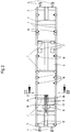
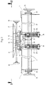
- the railway freight wagons shown schematically in FIGS. 1 and 2 has a base frame which essentially consists of two lateral outer longitudinal members 1 and cross members 2 connecting them to one another. At the ends, the outer longitudinal members 1 are connected to each other by a head member 3, which are each provided with two side buffers 4 in the exemplary embodiment.
- This freight wagon underframe rests on two bogies, of which only the wheels 5 are shown in the drawings for the sake of clarity.
- 6 wheel rugs 7 are formed in the area of the pocket.
- a support bracket 8 is used, which can be moved in the longitudinal direction of the rail freight wagon on a slideway 9, which extends over a certain length in the area of one end of the rail freight wagon in the middle between the outer side members 1, in particular from Fig. 2 emerges.
- 1 locking pin 10 are arranged on the outer longitudinal members, which come from a rest position can be brought into a working position, for example by pivoting about an axis running parallel to the longitudinal axis of the rail freight wagon.
- the locking pins 10 can also be designed to be displaceable over a limited area in the longitudinal direction of the outer longitudinal members 1.
- a loading table 12 is arranged at the end of the slideway 9, onto which the support bracket 8 can be pushed and which can be pivoted into a position in which it is located below the loading area 11.
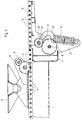
- This position of the loading table 12 provided with a support frame is shown in FIG. 6. 2, 3, 4 and 5, the support bracket 8 is located in the area of the slide 9, i.e. in one of his working positions, in which he is ready to receive the kingpin of a road vehicle semi-trailer.
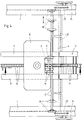
- a sprocket 13 is rotatably mounted on the support bracket 8 and engages in rack-like support members 14 which, according to FIGS. 4 to 6, both in the area of the slide 9 and the loading table 12 are arranged.
- These support members 14 act in the manner of the connecting bolts of a chain fixed in the region of the slideway 9 and the loading table 12, so that a rotation of the sprocket 13 results in a sliding movement of the support bracket 8.
- the sprocket 13 fastened on a shaft 15 is driven by a pair of gearwheels 16, of which one gearwheel is fastened on the shaft 15 and the other meshing gearwheel is fastened on a drive shaft 17 which is provided with a handwheel 18 at both ends is.
- the Length of the drive shaft 17 provided with the two handwheels 18 is shorter than the free space between the outer side members 1 (see FIGS. 3 and 4), so that it can be pivoted with the support bracket 8 into a rest position between the outer side members 1.
- the drive shaft 17 according to FIG. 4 can be moved in the longitudinal direction, as the double arrow in FIG. 4 indicates.
- the support frame 8 is brought into the respectively required position on the slide 9 using one of the handwheels 18. If, on the other hand, the rail freight wagon is to be used for the transport of containers and / or swap bodies, the support frame 8 is brought into the rest position shown in FIG. 6. For this purpose, it is moved onto the loading table 12 by means of one of the handwheels 18. This loading table 12 is then pivoted from the working position shown in FIG. 5 into the rest position shown in FIG. 6.
- this pivoting takes place with the aid of a pivot drive which can be seen in FIGS. 3 and 5 and 6.
- It consists of a gearwheel 19 which is fastened in a rotationally fixed manner on an axis 20 which is arranged on the underside of the loading table 12 in a non-rotating manner.
- This axis 20 also forms the pivot axis of the loading table 12, for which purpose it is arranged on the adjacent cross member 2.
- a drive wheel 21 engages in the gear wheel 19 and is seated on a shaft 22 which can be rotated via a gear 23 by means of a hand wheel 24.
- such a gear 23 with associated handwheel 24 is arranged at each end of the shaft 22 rotatably mounted on the outer longitudinal members 1, so that the pivot drive of the loading table 12 can be actuated from either side of the rail freight wagon.
- the pivoting drive for the loading table 12 is not self-locking.
- the loading table 12 can be pivoted through the container or swap body placed on the loading surface 11. So that in this case too, the loading table 12 returns to its working position after removal of the container or swap body, the loading table 12 is loaded by at least one spring 25, which guides it back into its working position.
- two such springs 25 are arranged, each of which is arranged on a lever 26 arranged between the loading table 12 and the freight wagon underframe.
- levers 26 can be moved into an over-center position by the pivoting drive when the loading table 12 is in its end position lying below the loading surface 11. This is shown in Fig. 6. It is ensured by this construction that the loading table 12 brought into its rest position by means of the pivoting drive remains in this position. 5 and 6 show the two end positions of one of the levers 26, each with one end the underside of the loading table 12 and the other end are mounted on a bracket 27, which in turn is attached to the adjacent cross member 2.
Landscapes
- Engineering & Computer Science (AREA)
- Transportation (AREA)
- Mechanical Engineering (AREA)
- Handcart (AREA)
- Loading Or Unloading Of Vehicles (AREA)
- Control Of Vehicles With Linear Motors And Vehicles That Are Magnetically Levitated (AREA)
- Machines For Laying And Maintaining Railways (AREA)
- Lock And Its Accessories (AREA)
- Auxiliary Methods And Devices For Loading And Unloading (AREA)
- Train Traffic Observation, Control, And Security (AREA)
- Transition And Organic Metals Composition Catalysts For Addition Polymerization (AREA)
- Processes Of Treating Macromolecular Substances (AREA)
Applications Claiming Priority (2)
| Application Number | Priority Date | Filing Date | Title |
|---|---|---|---|
| DE9105055U DE9105055U1 (de) | 1991-04-25 | 1991-04-25 | Eisenbahngüterwagen |
| DE9105055U | 1991-04-25 |
Publications (2)
| Publication Number | Publication Date |
|---|---|
| EP0510372A1 true EP0510372A1 (fr) | 1992-10-28 |
| EP0510372B1 EP0510372B1 (fr) | 1994-10-19 |
Family
ID=6866660
Family Applications (1)
| Application Number | Title | Priority Date | Filing Date |
|---|---|---|---|
| EP92105174A Expired - Lifetime EP0510372B1 (fr) | 1991-04-25 | 1992-03-26 | Wagon à marchandises |
Country Status (8)
| Country | Link |
|---|---|
| EP (1) | EP0510372B1 (fr) |
| AT (1) | ATE113013T1 (fr) |
| CZ (1) | CZ280189B6 (fr) |
| DE (2) | DE9105055U1 (fr) |
| DK (1) | DK0510372T3 (fr) |
| ES (1) | ES2065096T3 (fr) |
| FI (1) | FI921544A7 (fr) |
| PL (1) | PL168499B1 (fr) |
Cited By (6)
| Publication number | Priority date | Publication date | Assignee | Title |
|---|---|---|---|---|
| WO2009000707A1 (fr) * | 2007-06-22 | 2008-12-31 | Angiolo Barneschi | Wagon apte à être ouvert pour transporter des unités de chargement |
| US8286997B2 (en) | 2010-05-19 | 2012-10-16 | Midwest Industrial Door, Inc. | Trailer stabilizer |
| US8291592B2 (en) | 2010-03-17 | 2012-10-23 | Gunderson Llc | Method of lengthening a container well of a railcar |
| US8528929B2 (en) | 2010-01-21 | 2013-09-10 | Midwest Industrial Door, Inc. | Trailer docking repositionable support |
| US9656637B2 (en) | 2014-07-01 | 2017-05-23 | Stabilock, LLC | Trailer stabilization and restraint |
| DE102016224869A1 (de) * | 2016-12-13 | 2018-06-14 | Railadventure Gmbh | Transportvorrichtung |
Families Citing this family (12)
| Publication number | Priority date | Publication date | Assignee | Title |
|---|---|---|---|---|
| DE4118687C2 (de) * | 1991-06-07 | 1998-04-09 | Deutsche Waggonbau Ag | Fahrzeug-Mittenbereich für Taschenwagen |
| US5611285A (en) * | 1992-11-24 | 1997-03-18 | Gunderson, Inc. | Multipurpose railraod well car |
| US5423269A (en) * | 1992-11-24 | 1995-06-13 | Gunderson, Inc. | Railroad well car body including side sill reinforcing walkway structure |
| DE4433288A1 (de) * | 1994-09-19 | 1996-03-21 | Talbot Waggonfab | Schwenkbarer Ladetisch für Eisenbahn-Güterwagen |
| US5868379A (en) * | 1996-01-25 | 1999-02-09 | Rite-Hite Holding Corporation | Safety stand for trailer loading |
| US7607396B2 (en) | 2007-11-14 | 2009-10-27 | Gunderson Llc | Container car side sills |
| US7914042B2 (en) | 2008-05-13 | 2011-03-29 | Rite-Hite Holding Corporation | Support frame vehicle restraints |
| US7757610B2 (en) | 2008-07-30 | 2010-07-20 | Gunderson Llc | Shortened container well |
| DE102009015775B4 (de) | 2009-03-31 | 2021-11-25 | Cargobeamer Ag | Arretiervorrichtung zum Arretieren eines Königszapfens eines Sattelaufliegers, sowie Schienenwaggon mit einer derartigen Vorrichtung |
| US8177461B2 (en) | 2010-04-09 | 2012-05-15 | Gunderson Llc | Transport and storage of wheelsets |
| DE102020124841A1 (de) | 2020-09-23 | 2022-03-24 | Süddeutsche Gelenkscheibenfabrik Gesellschaft mit beschränkter Haftung & Co. KG. | Sattelplatte für einen Waggon |
| LT7063B (lt) * | 2022-11-03 | 2024-06-10 | Ab "Ltg Cargo" | Puspriekabės krovimo ir tvirtinimo sistema, ant 1520 mm geležinkelio vėžės platforminio vagono ir jos panaudojimo būdas |
Citations (2)
| Publication number | Priority date | Publication date | Assignee | Title |
|---|---|---|---|---|
| FR1559040A (fr) * | 1967-01-10 | 1969-03-07 | ||
| EP0404036A2 (fr) * | 1989-06-21 | 1990-12-27 | Rautaruukki Oy | Dispositif pour le positionnement d'une charge dans un wagon |
-
1991
- 1991-04-25 DE DE9105055U patent/DE9105055U1/de not_active Expired - Lifetime
-
1992
- 1992-03-26 DK DK92105174.4T patent/DK0510372T3/da active
- 1992-03-26 EP EP92105174A patent/EP0510372B1/fr not_active Expired - Lifetime
- 1992-03-26 DE DE59200644T patent/DE59200644D1/de not_active Expired - Fee Related
- 1992-03-26 AT AT92105174T patent/ATE113013T1/de not_active IP Right Cessation
- 1992-03-26 ES ES92105174T patent/ES2065096T3/es not_active Expired - Lifetime
- 1992-04-08 FI FI921544A patent/FI921544A7/fi not_active Application Discontinuation
- 1992-04-23 PL PL92294312A patent/PL168499B1/pl unknown
- 1992-04-24 CZ CS921260A patent/CZ280189B6/cs unknown
Patent Citations (2)
| Publication number | Priority date | Publication date | Assignee | Title |
|---|---|---|---|---|
| FR1559040A (fr) * | 1967-01-10 | 1969-03-07 | ||
| EP0404036A2 (fr) * | 1989-06-21 | 1990-12-27 | Rautaruukki Oy | Dispositif pour le positionnement d'une charge dans un wagon |
Non-Patent Citations (1)
| Title |
|---|
| I. ARTOBOLEVSKY 'Mechanisms in Modern Engineering Design' 1975 , MIR PUBLISHERS , MOSKAU * |
Cited By (10)
| Publication number | Priority date | Publication date | Assignee | Title |
|---|---|---|---|---|
| WO2009000707A1 (fr) * | 2007-06-22 | 2008-12-31 | Angiolo Barneschi | Wagon apte à être ouvert pour transporter des unités de chargement |
| US8528929B2 (en) | 2010-01-21 | 2013-09-10 | Midwest Industrial Door, Inc. | Trailer docking repositionable support |
| US9694790B2 (en) | 2010-01-21 | 2017-07-04 | Stabilock Llc | Trailer docking repositionable support |
| US8291592B2 (en) | 2010-03-17 | 2012-10-23 | Gunderson Llc | Method of lengthening a container well of a railcar |
| US8286997B2 (en) | 2010-05-19 | 2012-10-16 | Midwest Industrial Door, Inc. | Trailer stabilizer |
| US8567820B2 (en) | 2010-05-19 | 2013-10-29 | Midwest Industrial Door, Inc. | Trailer stabilizer |
| US8789850B2 (en) | 2010-05-19 | 2014-07-29 | Stabilock, LLC | Trailer stabilizer |
| US9656637B2 (en) | 2014-07-01 | 2017-05-23 | Stabilock, LLC | Trailer stabilization and restraint |
| DE102016224869A1 (de) * | 2016-12-13 | 2018-06-14 | Railadventure Gmbh | Transportvorrichtung |
| DE102016224869B4 (de) | 2016-12-13 | 2025-03-27 | Railadventure Gmbh | Transportvorrichtung |
Also Published As
| Publication number | Publication date |
|---|---|
| CZ280189B6 (cs) | 1995-11-15 |
| ATE113013T1 (de) | 1994-11-15 |
| PL294312A1 (en) | 1992-11-02 |
| FI921544A0 (fi) | 1992-04-08 |
| FI921544L (fi) | 1992-10-26 |
| ES2065096T3 (es) | 1995-02-01 |
| PL168499B1 (pl) | 1996-02-29 |
| CS126092A3 (en) | 1992-11-18 |
| EP0510372B1 (fr) | 1994-10-19 |
| DE9105055U1 (de) | 1991-06-13 |
| FI921544A7 (fi) | 1992-10-26 |
| DE59200644D1 (de) | 1994-11-24 |
| DK0510372T3 (da) | 1995-03-27 |
Similar Documents
| Publication | Publication Date | Title |
|---|---|---|
| EP0510372A1 (fr) | Wagon à marchandises | |
| EP0510467B1 (fr) | Wagon à marchandises | |
| DE1913576A1 (de) | Container-Unterwagen | |
| DE69330237T2 (de) | Kupplungseinheit zwischen zwei aufeinander folgenden Waggons und einem gemeinsamen Drehgestell | |
| DE69204106T2 (de) | Universalkupplungsadapter für Schienen- und Strassenfahrzeuge. | |
| EP0019098B1 (fr) | Wagon couvert | |
| DE68922096T2 (de) | Intermodales strassen/schienen-transportsystem. | |
| DE3234374A1 (de) | Eisenbahn-gueterwagen zum transport von strassenfahrzeugen | |
| DE3911138A1 (de) | Untergestell fuer zweiachsige eisenbahngueterwagen | |
| DE4120035A1 (de) | Einarmiger radvorleger fuer autotransport-gueterwagen | |
| DE1029027B (de) | Zusammenklappbare Stuetze fuer einen Frachtgutbehaelter, insbesondere einen Sattelschlepper | |
| DE2930698C2 (de) | Fahrzeug für den Transport von Wechselaufbauten | |
| DE1012949B (de) | Vorrichtung zur Anpassung der Stuetzradgestelle von fuer den Strassenverkehr in Verbindung mit Sattelschleppern zu verwendenden Anhaengern an das Aufnahmegleis von auf Schienen fahrenden Traegerfahrzeugen fuer den Eisenbahntransport | |
| DE3046022A1 (de) | Mit sattelkupplung ausgeruestete zugmaschine | |
| DE3530321C2 (fr) | ||
| DE69803487T2 (de) | Sattelkupplungsanordnung für ein auf gleisen verfahrbares fahrzeug | |
| EP0900707B9 (fr) | Wagon articulé pour le transport combiné, notammment de véhicules routiers | |
| DE69511673T2 (de) | Auf Eisenbahnwagen transportierbare Rampen zum Verladen von Standard-Sattelaufliegern auf, aus besonderen Einheiten zusammengestellte, Züge | |
| EP0538648B1 (fr) | Wagon porteur pour le transport combiné rail-route | |
| DE3502226A1 (de) | Schienengebundenes transportfahrzeug, insbesondere zum transport von personenkraftwagen | |
| DE69708532T2 (de) | Schienenfahrzeug für den kombinierten Schiene/-Strasse/-Transport und Zug mit solchem Fahrzeug | |
| DE2821697C2 (fr) | ||
| EP0042942A1 (fr) | Dispositif pour le support du pivot d'attelage pour le transport de semi-remorques sur wagons ferroviaires | |
| DE1128456B (de) | Zweiwegefahrzeug | |
| DE646318C (de) | Anhaengerkupplung fuer einen Vierradanhaenger mit einem Sattelschlepper |
Legal Events
| Date | Code | Title | Description |
|---|---|---|---|
| PUAI | Public reference made under article 153(3) epc to a published international application that has entered the european phase |
Free format text: ORIGINAL CODE: 0009012 |
|
| AK | Designated contracting states |
Kind code of ref document: A1 Designated state(s): AT BE CH DE DK ES FR GB GR IT LI LU NL PT SE |
|
| 17P | Request for examination filed |
Effective date: 19920911 |
|
| 17Q | First examination report despatched |
Effective date: 19931025 |
|
| GRAA | (expected) grant |
Free format text: ORIGINAL CODE: 0009210 |
|
| AK | Designated contracting states |
Kind code of ref document: B1 Designated state(s): AT BE CH DE DK ES FR GB GR IT LI LU NL PT SE |
|
| PG25 | Lapsed in a contracting state [announced via postgrant information from national office to epo] |
Ref country code: GR Free format text: LAPSE BECAUSE OF FAILURE TO SUBMIT A TRANSLATION OF THE DESCRIPTION OR TO PAY THE FEE WITHIN THE PRESCRIBED TIME-LIMIT Effective date: 19941019 |
|
| REF | Corresponds to: |
Ref document number: 113013 Country of ref document: AT Date of ref document: 19941115 Kind code of ref document: T |
|
| REF | Corresponds to: |
Ref document number: 59200644 Country of ref document: DE Date of ref document: 19941124 |
|
| GBT | Gb: translation of ep patent filed (gb section 77(6)(a)/1977) |
Effective date: 19941103 |
|
| ET | Fr: translation filed | ||
| ITF | It: translation for a ep patent filed | ||
| EAL | Se: european patent in force in sweden |
Ref document number: 92105174.4 |
|
| REG | Reference to a national code |
Ref country code: ES Ref legal event code: FG2A Ref document number: 2065096 Country of ref document: ES Kind code of ref document: T3 |
|
| REG | Reference to a national code |
Ref country code: DK Ref legal event code: T3 |
|
| PG25 | Lapsed in a contracting state [announced via postgrant information from national office to epo] |
Ref country code: LU Free format text: LAPSE BECAUSE OF NON-PAYMENT OF DUE FEES Effective date: 19950331 |
|
| SC4A | Pt: translation is available |
Free format text: 941020 AVAILABILITY OF NATIONAL TRANSLATION |
|
| PLBE | No opposition filed within time limit |
Free format text: ORIGINAL CODE: 0009261 |
|
| STAA | Information on the status of an ep patent application or granted ep patent |
Free format text: STATUS: NO OPPOSITION FILED WITHIN TIME LIMIT |
|
| 26N | No opposition filed | ||
| PGFP | Annual fee paid to national office [announced via postgrant information from national office to epo] |
Ref country code: GB Payment date: 19960312 Year of fee payment: 5 |
|
| PGFP | Annual fee paid to national office [announced via postgrant information from national office to epo] |
Ref country code: PT Payment date: 19960314 Year of fee payment: 5 |
|
| PGFP | Annual fee paid to national office [announced via postgrant information from national office to epo] |
Ref country code: SE Payment date: 19960321 Year of fee payment: 5 Ref country code: BE Payment date: 19960321 Year of fee payment: 5 |
|
| PGFP | Annual fee paid to national office [announced via postgrant information from national office to epo] |
Ref country code: DK Payment date: 19960322 Year of fee payment: 5 |
|
| PGFP | Annual fee paid to national office [announced via postgrant information from national office to epo] |
Ref country code: NL Payment date: 19960328 Year of fee payment: 5 |
|
| PGFP | Annual fee paid to national office [announced via postgrant information from national office to epo] |
Ref country code: ES Payment date: 19960329 Year of fee payment: 5 |
|
| PGFP | Annual fee paid to national office [announced via postgrant information from national office to epo] |
Ref country code: FR Payment date: 19970211 Year of fee payment: 6 |
|
| PGFP | Annual fee paid to national office [announced via postgrant information from national office to epo] |
Ref country code: AT Payment date: 19970320 Year of fee payment: 6 |
|
| PGFP | Annual fee paid to national office [announced via postgrant information from national office to epo] |
Ref country code: CH Payment date: 19970324 Year of fee payment: 6 |
|
| PG25 | Lapsed in a contracting state [announced via postgrant information from national office to epo] |
Ref country code: GB Effective date: 19970326 Ref country code: DK Effective date: 19970326 |
|
| REG | Reference to a national code |
Ref country code: DK Ref legal event code: EBP |
|
| PG25 | Lapsed in a contracting state [announced via postgrant information from national office to epo] |
Ref country code: SE Effective date: 19970327 |
|
| PG25 | Lapsed in a contracting state [announced via postgrant information from national office to epo] |
Ref country code: ES Free format text: LAPSE BECAUSE OF NON-PAYMENT OF DUE FEES Effective date: 19970329 |
|
| PG25 | Lapsed in a contracting state [announced via postgrant information from national office to epo] |
Ref country code: BE Effective date: 19970331 |
|
| PGFP | Annual fee paid to national office [announced via postgrant information from national office to epo] |
Ref country code: DE Payment date: 19970403 Year of fee payment: 6 |
|
| BERE | Be: lapsed |
Owner name: WAGGONFABRIK TALBOT Effective date: 19970331 |
|
| PG25 | Lapsed in a contracting state [announced via postgrant information from national office to epo] |
Ref country code: PT Effective date: 19970930 |
|
| PG25 | Lapsed in a contracting state [announced via postgrant information from national office to epo] |
Ref country code: NL Effective date: 19971001 |
|
| GBPC | Gb: european patent ceased through non-payment of renewal fee |
Effective date: 19970326 |
|
| NLV4 | Nl: lapsed or anulled due to non-payment of the annual fee |
Effective date: 19971001 |
|
| EUG | Se: european patent has lapsed |
Ref document number: 92105174.4 |
|
| REG | Reference to a national code |
Ref country code: PT Ref legal event code: MM4A Free format text: LAPSE DUE TO NON-PAYMENT OF FEES Effective date: 19970930 |
|
| PG25 | Lapsed in a contracting state [announced via postgrant information from national office to epo] |
Ref country code: AT Free format text: LAPSE BECAUSE OF NON-PAYMENT OF DUE FEES Effective date: 19980326 |
|
| PG25 | Lapsed in a contracting state [announced via postgrant information from national office to epo] |
Ref country code: LI Free format text: LAPSE BECAUSE OF NON-PAYMENT OF DUE FEES Effective date: 19980331 Ref country code: FR Free format text: THE PATENT HAS BEEN ANNULLED BY A DECISION OF A NATIONAL AUTHORITY Effective date: 19980331 Ref country code: CH Free format text: LAPSE BECAUSE OF NON-PAYMENT OF DUE FEES Effective date: 19980331 |
|
| REG | Reference to a national code |
Ref country code: CH Ref legal event code: PL |
|
| PG25 | Lapsed in a contracting state [announced via postgrant information from national office to epo] |
Ref country code: DE Free format text: LAPSE BECAUSE OF NON-PAYMENT OF DUE FEES Effective date: 19981201 |
|
| REG | Reference to a national code |
Ref country code: FR Ref legal event code: ST |
|
| REG | Reference to a national code |
Ref country code: ES Ref legal event code: FD2A Effective date: 19990503 |
|
| PG25 | Lapsed in a contracting state [announced via postgrant information from national office to epo] |
Ref country code: IT Free format text: LAPSE BECAUSE OF NON-PAYMENT OF DUE FEES Effective date: 20050326 |