EP0510496A1 - Schiefscheibenverdichter mit variablem Hubmechanismus - Google Patents
Schiefscheibenverdichter mit variablem Hubmechanismus Download PDFInfo
- Publication number
- EP0510496A1 EP0510496A1 EP92106456A EP92106456A EP0510496A1 EP 0510496 A1 EP0510496 A1 EP 0510496A1 EP 92106456 A EP92106456 A EP 92106456A EP 92106456 A EP92106456 A EP 92106456A EP 0510496 A1 EP0510496 A1 EP 0510496A1
- Authority
- EP
- European Patent Office
- Prior art keywords
- drive shaft
- cylinder block
- bearing
- compressor
- slant plate
- Prior art date
- Legal status (The legal status is an assumption and is not a legal conclusion. Google has not performed a legal analysis and makes no representation as to the accuracy of the status listed.)
- Withdrawn
Links
- 230000007246 mechanism Effects 0.000 title claims abstract description 31
- 238000006073 displacement reaction Methods 0.000 title abstract description 14
- 230000002093 peripheral effect Effects 0.000 claims description 16
- 230000008859 change Effects 0.000 claims description 9
- 238000004891 communication Methods 0.000 claims description 7
- 230000008878 coupling Effects 0.000 claims description 5
- 238000010168 coupling process Methods 0.000 claims description 5
- 238000005859 coupling reaction Methods 0.000 claims description 5
- 230000004044 response Effects 0.000 claims description 5
- 238000005096 rolling process Methods 0.000 claims description 4
- 239000003507 refrigerant Substances 0.000 description 6
- 238000000034 method Methods 0.000 description 4
- 230000008569 process Effects 0.000 description 4
- 230000002159 abnormal effect Effects 0.000 description 3
- 238000005299 abrasion Methods 0.000 description 3
- 238000006243 chemical reaction Methods 0.000 description 3
- 238000001816 cooling Methods 0.000 description 3
- 230000004323 axial length Effects 0.000 description 2
- 238000010276 construction Methods 0.000 description 2
- 230000007423 decrease Effects 0.000 description 2
- 230000003247 decreasing effect Effects 0.000 description 2
- 230000000694 effects Effects 0.000 description 2
- 238000003780 insertion Methods 0.000 description 2
- 230000037431 insertion Effects 0.000 description 2
- 238000004519 manufacturing process Methods 0.000 description 2
- 235000014676 Phragmites communis Nutrition 0.000 description 1
- 238000004378 air conditioning Methods 0.000 description 1
- 230000001419 dependent effect Effects 0.000 description 1
- 235000015250 liver sausages Nutrition 0.000 description 1
- 230000013011 mating Effects 0.000 description 1
- 238000012986 modification Methods 0.000 description 1
- 230000004048 modification Effects 0.000 description 1
Images


Classifications
-
- F—MECHANICAL ENGINEERING; LIGHTING; HEATING; WEAPONS; BLASTING
- F04—POSITIVE - DISPLACEMENT MACHINES FOR LIQUIDS; PUMPS FOR LIQUIDS OR ELASTIC FLUIDS
- F04B—POSITIVE-DISPLACEMENT MACHINES FOR LIQUIDS; PUMPS
- F04B27/00—Multi-cylinder pumps specially adapted for elastic fluids and characterised by number or arrangement of cylinders
- F04B27/08—Multi-cylinder pumps specially adapted for elastic fluids and characterised by number or arrangement of cylinders having cylinders coaxial with, or parallel or inclined to, main shaft axis
- F04B27/14—Control
- F04B27/16—Control of pumps with stationary cylinders
- F04B27/18—Control of pumps with stationary cylinders by varying the relative positions of a swash plate and a cylinder block
- F04B27/1804—Controlled by crankcase pressure
-
- F—MECHANICAL ENGINEERING; LIGHTING; HEATING; WEAPONS; BLASTING
- F04—POSITIVE - DISPLACEMENT MACHINES FOR LIQUIDS; PUMPS FOR LIQUIDS OR ELASTIC FLUIDS
- F04B—POSITIVE-DISPLACEMENT MACHINES FOR LIQUIDS; PUMPS
- F04B27/00—Multi-cylinder pumps specially adapted for elastic fluids and characterised by number or arrangement of cylinders
- F04B27/08—Multi-cylinder pumps specially adapted for elastic fluids and characterised by number or arrangement of cylinders having cylinders coaxial with, or parallel or inclined to, main shaft axis
- F04B27/10—Multi-cylinder pumps specially adapted for elastic fluids and characterised by number or arrangement of cylinders having cylinders coaxial with, or parallel or inclined to, main shaft axis having stationary cylinders
- F04B27/1036—Component parts, details, e.g. sealings, lubrication
- F04B27/1054—Actuating elements
- F04B27/1063—Actuating-element bearing means or driving-axis bearing means
-
- F—MECHANICAL ENGINEERING; LIGHTING; HEATING; WEAPONS; BLASTING
- F04—POSITIVE - DISPLACEMENT MACHINES FOR LIQUIDS; PUMPS FOR LIQUIDS OR ELASTIC FLUIDS
- F04B—POSITIVE-DISPLACEMENT MACHINES FOR LIQUIDS; PUMPS
- F04B27/00—Multi-cylinder pumps specially adapted for elastic fluids and characterised by number or arrangement of cylinders
- F04B27/08—Multi-cylinder pumps specially adapted for elastic fluids and characterised by number or arrangement of cylinders having cylinders coaxial with, or parallel or inclined to, main shaft axis
- F04B27/14—Control
- F04B27/16—Control of pumps with stationary cylinders
- F04B27/18—Control of pumps with stationary cylinders by varying the relative positions of a swash plate and a cylinder block
- F04B27/1804—Controlled by crankcase pressure
- F04B2027/1809—Controlled pressure
- F04B2027/1813—Crankcase pressure
-
- F—MECHANICAL ENGINEERING; LIGHTING; HEATING; WEAPONS; BLASTING
- F04—POSITIVE - DISPLACEMENT MACHINES FOR LIQUIDS; PUMPS FOR LIQUIDS OR ELASTIC FLUIDS
- F04B—POSITIVE-DISPLACEMENT MACHINES FOR LIQUIDS; PUMPS
- F04B27/00—Multi-cylinder pumps specially adapted for elastic fluids and characterised by number or arrangement of cylinders
- F04B27/08—Multi-cylinder pumps specially adapted for elastic fluids and characterised by number or arrangement of cylinders having cylinders coaxial with, or parallel or inclined to, main shaft axis
- F04B27/14—Control
- F04B27/16—Control of pumps with stationary cylinders
- F04B27/18—Control of pumps with stationary cylinders by varying the relative positions of a swash plate and a cylinder block
- F04B27/1804—Controlled by crankcase pressure
- F04B2027/1822—Valve-controlled fluid connection
- F04B2027/1827—Valve-controlled fluid connection between crankcase and discharge chamber
-
- F—MECHANICAL ENGINEERING; LIGHTING; HEATING; WEAPONS; BLASTING
- F04—POSITIVE - DISPLACEMENT MACHINES FOR LIQUIDS; PUMPS FOR LIQUIDS OR ELASTIC FLUIDS
- F04B—POSITIVE-DISPLACEMENT MACHINES FOR LIQUIDS; PUMPS
- F04B27/00—Multi-cylinder pumps specially adapted for elastic fluids and characterised by number or arrangement of cylinders
- F04B27/08—Multi-cylinder pumps specially adapted for elastic fluids and characterised by number or arrangement of cylinders having cylinders coaxial with, or parallel or inclined to, main shaft axis
- F04B27/14—Control
- F04B27/16—Control of pumps with stationary cylinders
- F04B27/18—Control of pumps with stationary cylinders by varying the relative positions of a swash plate and a cylinder block
- F04B27/1804—Controlled by crankcase pressure
- F04B2027/1822—Valve-controlled fluid connection
- F04B2027/1831—Valve-controlled fluid connection between crankcase and suction chamber
-
- F—MECHANICAL ENGINEERING; LIGHTING; HEATING; WEAPONS; BLASTING
- F04—POSITIVE - DISPLACEMENT MACHINES FOR LIQUIDS; PUMPS FOR LIQUIDS OR ELASTIC FLUIDS
- F04B—POSITIVE-DISPLACEMENT MACHINES FOR LIQUIDS; PUMPS
- F04B27/00—Multi-cylinder pumps specially adapted for elastic fluids and characterised by number or arrangement of cylinders
- F04B27/08—Multi-cylinder pumps specially adapted for elastic fluids and characterised by number or arrangement of cylinders having cylinders coaxial with, or parallel or inclined to, main shaft axis
- F04B27/14—Control
- F04B27/16—Control of pumps with stationary cylinders
- F04B27/18—Control of pumps with stationary cylinders by varying the relative positions of a swash plate and a cylinder block
- F04B27/1804—Controlled by crankcase pressure
- F04B2027/184—Valve controlling parameter
- F04B2027/1854—External parameters
-
- F—MECHANICAL ENGINEERING; LIGHTING; HEATING; WEAPONS; BLASTING
- F04—POSITIVE - DISPLACEMENT MACHINES FOR LIQUIDS; PUMPS FOR LIQUIDS OR ELASTIC FLUIDS
- F04B—POSITIVE-DISPLACEMENT MACHINES FOR LIQUIDS; PUMPS
- F04B27/00—Multi-cylinder pumps specially adapted for elastic fluids and characterised by number or arrangement of cylinders
- F04B27/08—Multi-cylinder pumps specially adapted for elastic fluids and characterised by number or arrangement of cylinders having cylinders coaxial with, or parallel or inclined to, main shaft axis
- F04B27/14—Control
- F04B27/16—Control of pumps with stationary cylinders
- F04B27/18—Control of pumps with stationary cylinders by varying the relative positions of a swash plate and a cylinder block
- F04B27/1804—Controlled by crankcase pressure
- F04B2027/184—Valve controlling parameter
- F04B2027/1859—Suction pressure
-
- F—MECHANICAL ENGINEERING; LIGHTING; HEATING; WEAPONS; BLASTING
- F04—POSITIVE - DISPLACEMENT MACHINES FOR LIQUIDS; PUMPS FOR LIQUIDS OR ELASTIC FLUIDS
- F04B—POSITIVE-DISPLACEMENT MACHINES FOR LIQUIDS; PUMPS
- F04B2201/00—Pump parameters
- F04B2201/12—Parameters of driving or driven means
- F04B2201/1201—Rotational speed of the axis
Definitions
- the present invention relates to a refrigerant compressor, and more particularly, to a slant plate type compressor with a variable displacement mechanism, such as a wobble plate type compressor with a variable displacement mechanism for use in an automotive air conditioning system.
- Figure 1 illustrates a wobble plate type compressor with a variable displacement mechanism disclosed in U.S. Patent No. 4,606,705 to Parekh et. al..
- the left side of the Figure will be referenced as the forward end or front and the right side of the Figure will be referenced as the rearward end.
- Compressor 100 includes compressor housing 101, cylinder block 102 having a plurality of cylinders 103 formed therein, driving mechanism 104 having drive shaft 105 and slant plate 106, wobble plate 107 which is rotatably mounted on slant plate 106 and nutates when drive shaft 105 and slant plate 106 rotate, and rotation preventing mechanism 108 which prevents rotation of wobble plate 107 during nutational motion of wobble plate 107.
- Pistons 109 are slidably disposed in respective cylinders 103 and are connected to wobble plate 107 through respective connecting rods 110. The nutational motion of wobble plate 107 causes pistons 109 to reciprocate in respective cylinders 103 to compress refrigerant therein.
- Crank chamber 111 is defined by housing 101 and a front end of cylinder block 102.
- Suction chamber 112 is defined in housing 101 rear to cylinder block 102.
- Valve control mechanism 113 is disposed in housing 101 and controls to communicate and block a communication between crank chamber 111 and suction chamber 112 in response to changes in suction chamber pressure in order to vary crank chamber pressure.
- the changes in the crank chamber pressure varies a slant angle of slant plate 106 with respect to a plane perpendicular to the axis of drive shaft 105.
- the changes in the slant angle of slant plate 106 varies a stroke length of each pistons 109 so that a capacity of compressor 100 changes. Therefore, the capacity of compressor 100 is varied by the operation of valve control mechanism 113.
- Thrust needle bearing 101b surrounding drive shaft 105 is disposed between an inner end surface of the front end of housing 101 and a front end of annular cylindrical member 114 fixedly connected to drive shaft 105 by pin member 115.
- Thrust needle bearing 101b receives a forward force generated by gas pressure reaction force of the compressed refrigerant in cylinders 103 through pistons 109, connecting rods 110, wobble plate 107, slant plate 106, drive shaft 105 and annular cylindrical member 114.
- First annular groove 105c is formed at an outer peripheral surface of an inner rear end portion of drive shaft 105 forward to cylinder block 102.
- Split ring return spring 116 is fixedly received in first annular groove 105c by snap portion 116a.
- slant plate 106 When slant plate 106 reaches its minimum slant angle, it is contacted by split ring return spring 116, and the restoring force of split ring return spring 116 urges it back towards greater slant angles. Therefore, when slant plate 106 contacts with split ring return spring 116, a rearward force acting on drive shaft 105 is generated. The rearward force is increased in directly proportional to an increase in the restoring force of split ring return spring 116. When the rearward force generated by the contact of slant plate 106 to split ring return spring 116 becomes greater than the forward force generated by the gas pressure reaction force in cylinders 103, drive shaft 105 tends to move rearwardly.
- drive shaft 105 includes small diameter portion 105a which is integral with and extends from an inner rear end of drive shaft 105, thereby forming annular ridge 105b at the inner rear end of drive shaft 105.
- Annular ridge 105b is located forward to cylinder block 102.
- Small diameter portion 105a of drive shaft 105 is rotatably supported by cylinder block 102 through needle bearing 102a which is fixedly disposed in central bore 117 formed through cylinder block 102. Needle bearing 102a is fixedly disposed in central bore 117 by, for example, forcible insertion.
- Second annular groove 105d rearwardly extending from annular ridge 105b is formed at an outer peripheral surface of small diameter portion 105a of drive shaft 105.
- Washer 118 is slidably received in second annular groove 105d, and is sandwiched by annular ridge 105b and cylinder block 102 so as to prevent the rearward movement of drive shaft 105.
- the axial length of second annular groove 105d is designed so as to be able to receive washer 118 of which thickness is sufficient large. Washer 118 radially extends so as to be contacted to the front end surface of cylinder block 102.
- washer 118 is selected that the thickness thereof is equal to or slightly smaller than the clearance created between the side wall of annular ridge 105b and the front end surface of cylinder block 102 in order to effectively prevent the rearward movement of drive shaft 105.
- washer 118 may collide the front end surface of cylinder block 102 and the side wall of annular ridge 105b of drive shaft 105 because that washer 118 is slidably received in second annular groove 105d.
- the collision between washer 118 and cylinder block 102, and annular ridge 105b causes an offensive noise.
- Figure 3 substantially illustrates a relevant part of a wobble plate type compressor with a variable displacement mechanism as sold in a commercial market.
- the same numerals are used to denote the corresponding elements shown in Figures 1 and 2 so that an explanation thereof is omitted.
- thrust bearing 120 is slidably mounted about small diameter portion 105a of drive shaft 105 between the side wall of annular ridge 105b and the front end surface of cylinder block 102. Thrust bearing 120 radially extends so as to be contacted to the front end surface of cylinder block 102. Thrust bearing 120 is selected that the thickness thereof is equal to or slightly smaller than the clearance created between the side wall of annular ridge 105b of drive shaft 105 and the front end surface of cylinder block 102. Thrust bearing 120 effectively receive the rearward thrust force generated when drive shaft 105 tends to move rearwardly so that no abnormal abrasion is occurred on the front end surface of cylinder block 102 and the side wall of annular ridge 105b.
- thrust bearing 120 is mistakenly selected such that the thickness thereof is smaller than the clearance created between the side wall of annular ridge 105b and the front end surface of cylinder block 102, the drawback, such as, the collision between thrust bearing 120 and cylinder block 102, and annular ridge 105b is occurred as well as Parekh et. al..
- Figure 4 substantially illustrates a relevant part of a wobble plate type compressor with a variable displacement mechanism as disclosed in Japanese Patent Application Publication No. 1- 267374.
- the same numerals are used to denote the corresponding elements shown in Figures 1 and 2 so that an explanation thereof is omitted.
- thrust bearing 120 and belleville spring 121 rear to thrust bearing 120 are mounted about small diameter portion 105a of drive shaft 105 between the side wall of annular ridge 105b and the front end surface of cylinder block 102.
- Thrust bearing 120 is slidably mounted about small diameter portion 105a.
- Spring 121 is compressedly sandwiched by thrust bearing 120 and cylinder block 102 so that thrust bearing 120 is continuously urged forwardly by virtue of the restoring force of spring 121. Therefore, even though the clearance created between the side wall of annular groove 105b and the front end surface of cylinder block 102 is varied, the clearance is filled up by spring 121 through thrust bearing 120 without selecting the thickness of thrust bearing 120.
- thrust bearing 120 effectively receive the rearward thrust force generated when drive shaft 105 tends to move rearwardly so that no abnormal abrasion is occurred on the front end surface of cylinder block 102 and the side wall of annular ridge 105b.
- thrust bearing 120 is continuously urged forwardly by the restoring force of belleville spring 121, a rolling friction between the component parts of thrust bearing 120 is increased so that the life of thrust bearing 120 is decreased. Furthermore, the provision of relatively costly thrust bearing 120 causes an increase in a manufacturing cost of the compressor. Still furthermore, the provision of belleville spring 121 in addition to thrust bearing 120 causes an increase in the number of the component parts of the compressor.
- a slant plate type compressor such as a wobble plate type compressor includes a compressor housing which encloses a crank chamber, a suction chamber and a discharge chamber therein.
- the compressor housing comprises a cylinder block having a plurality of cylinders.
- a piston slidably fitted within each of the cylinders.
- a drive mechanism coupled to the pistons for reciprocating the pistons within the cylinders.
- the drive mechanism includes a drive shaft rotatably supported in the housing.
- a coupling mechanism for drivingly couples the pistons with the drive shaft and for converting rotary motion of the drive shaft into reciprocating motion of the pistons.
- the coupling mechanism includes a slant plate having a surface disposed at an incline angle relative to a plane perpendicular to an axis of the drive shaft. The incline angle changes in response to a change in pressure in the crank chamber to change the capacity of the compressor.
- a communication path links the crank chamber with the suction chamber.
- a valve control mechanism controls the opening and closing of the communication path to cause a change in pressure in the crank chamber.
- the drive shaft includes a small diameter portion extending from one end thereof so that an annular ridge is formed at the one end of the drive shaft.
- the small diameter portion of the drive shaft rotatably supported in a bore formed through the cylinder block through a bearing, such as a radial ball bearing.
- the radial ball bearing includes an outer annular ring and an inner annular ring and a plurality of rolling elements, such as ball elements rollingly disposed between the outer and inner annular rings.
- the bearing receives both an axial and a radial forces acting on the drive shaft through the outer and inner annular rings and ball elements.
- An outer peripheral surface of the outer annular ring of the bearing frictionally engages with an inner peripheral wall of the bore.
- the inner ring slidably receives the small diameter portion of the drive shaft therewithin while one end of the inner annular ring is in contact with a side wall of the annular ridge of the drive shaft.
- Figure 1 is a longitudinal sectional view of a wobble plate type compressor with a variable displacement mechanism in accordance with one prior art.
- Figure 2 is a sectional view of a relevant part shown in Figure 1.
- Figure 3 is a view similar to Figure 2 substantially illustrating a relevant part of a wobble plate type compressor with a variable displacement mechanism in accordance with another prior art.
- Figure 4 is a view similar to Figure 2 substantially illustrating a relevant part of a wobble plate type compressor with a variable displacement mechanism in accordance with still another prior art.
- Figure 5 is a longitudinal sectional view of a wobble plate type compressor with a variable displacement mechanism in accordance with a first embodiment of the present invention.
- Figure 6 is a sectional view of a relevant part shown in Figure 5.
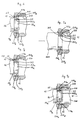
- Figure 7a-7c are views similar to Figure 6 illustrating a process of fixedly disposing a radial ball bearing between an outer peripheral surface of an inner rear end portion of a drive shaft and an inner peripheral wall of a front end portion of a central bore formed through a cylinder block.
- Figure 8 is a view similar to Figure 6 illustrating a relevant part of a wobble plate type compressor with a variable displacement mechanism in accordance with a second embodiment of the present invention.
- Figure 9 is a view similar to Figure 6 illustrating a relevant part of a wobble plate type compressor with a variable displacement mechanism in accordance with a third embodiment of the present invention.
- Figure 10 is a view similar to Figure 6 illustrating a relevant part of a wobble plate type compressor with a variable displacement mechanism in accordance with a fourth embodiment of the present invention.
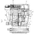
- wobble plate type compressor 10 in accordance with a first embodiment of the present invention is shown.
- the left side of the Figure will be referenced as the forward end or front and the right side of the Figure will be referenced as the rearward end.
- Compressor 10 includes cylindrical housing assembly 20 including cylinder block 21, front end plate 23 disposed at one end of cylinder block 21, crank chamber 22 formed between cylinder block 21 and front end plate 23, and rear end plate 24 disposed at the opposite end of cylinder block 21.
- Front end plate 23 is mounted on the open forward end of cylinder block 21 by a plurality of bolts 23a to enclose crank chamber 22 therein.
- Rear end plate 24 is mounted on cylinder block 21 at its opposite end by a plurality of bolts 24a.
- Valve plate 25 is located between rear end plate 24 and cylinder block 21. Opening 231 is centrally formed in front end plate 23.
- Drive shaft 26 is supported by bearing 30 disposed in opening 231.
- Drive shaft 26 includes small diameter portion 26a which is integral with and extends from an inner rear end of drive shaft 26, thereby forming annular ridge 26b at the inner rear end of drive shaft 26.
- Central bore 210 extends through cylinder block 21 to a forward end surface of cylinder block 210.
- Small diameter portion 26a of drive shaft 26 is rotatably supported by bearing 31 disposed within central bore 210. The relationship between small diameter portion 26a of drive shaft 26, bearing 31 and central bore 210 will be later described in detail.
- Valve control mechanism 19 is disposed in bore 210 to the rear of drive shaft 26.
- Cam rotor 40 is fixed on drive shaft 26 by pin member 261, and rotates with shaft 26.
- Thrust needle bearing 32 is disposed between the axial inner (rear) end surface of front end plate 23 and the adjacent forward axial end surface of cam rotor 40.
- Cam rotor 40 includes arm 41 having pin member 42 extending therefrom.
- Slant plate 50 is disposed about drive shaft 26 and includes opening 53 through which drive shaft 26 passes.
- opening 53 is described in U.S. Patent No. 4,846,049 to Terauchi. As relevance to the present invention, Terauchi substantially discloses in U.S. '049 patent that the maximum and minimum slant angles of slant plate 50 are determined by the configuration of opening 53. Slant plate 50 is disposed adjacent cam rotor 40.
- Slant plate 50 includes arm 51 having slot 52, and boss 54.
- Cam rotor 40 and slant plate 50 are connected by pin member 42, which is inserted in slot 52 to create a hinged joint.
- Pin member 42 is slidable within slot 52 to allow adjustment of the angular position of slant plate 50 with respect to the longitudinal axis of drive shaft 26.
- Wobble plate 60 is mounted about boss 54 of slant plate 50 through bearings 61 and 62 so that slant plate 50 is rotatable with respect thereto. Rotational motion of slant plate 50 causes nutational motion of wobble plate 60.
- Fork-shaped slider 63 is attached to the outer peripheral end of wobble plate 60 and is slidably mounted on sliding rail 64 held between front end plate 23 and cylinder block 21. Fork-shaped slider 63 prevents rotation of wobble plate 60 and wobble plate 60 reciprocates along rail 64 when cam rotor 40 and slant plate 50 rotate.
- Cylinder block 21 includes a plurality of peripherally located cylinder chambers 70 in which pistons 71 reciprocate. Each piston 71 is connected to wobble plate 60 at a peripheral location by a corresponding connecting rod 72. Nutational motion of wobble plate 60 causes pistons 71 to reciprocate in cylinders 70 to compress refrigerant therein.
- Rear end plate 24 includes peripherally located annular suction chamber 241 and centrally located discharge chamber 251.
- Valve plate 25 is located between cylinder block 21 and rear end plate 24 and includes a plurality of valved suction ports 242 linking suction chamber 241 with respective cylinders 70.
- Valve plate 25 also includes a plurality of valved discharge ports 252 linking discharge chamber 251 with respective cylinders 70.
- Suction ports 242 and discharge ports 252 are provided with suitable reed valves as described in U.S. Patent No. 4,011,029 to Shimizu.
- Suction chamber 241 includes inlet portion 241a which is connected to an evaporator of the external cooling circuit (not shown).
- Discharge chamber 251 is provided with outlet portion 251a connected to a condenser of the cooling circuit (not shown).
- Gaskets 27 and 28 are located between cylinder block 21 and the front surface of valve plate 25, and the rear surface of valve plate 25 and rear end plate 24, respectively, to seal the mating surfaces of cylinder block 21, valve plate 25 and rear end plate 24.
- Communication path 600 links crank chamber 22 and suction chamber 241 and includes central bore 210 and passageway 150.
- Valve control mechanism 19 controls the opening and closing of communication path 600 in order to vary the capacity of the compressor, as disclosed in U.S. Patent No. 4,960,367 to Terauchi.
- drive shaft 26 is rotated by the engine of the vehicle through electromagnetic clutch 300.
- Cam rotor 40 is rotated with drive shaft 26, rotating slant plate 50 as well, causing wobble plate 60 to nutate.
- Nutational motion of wobble plate 60 reciprocates pistons 71 in their respective cylinders 70.
- refrigerant gas which is introduced into suction chamber 241 through inlet portion 241a, flows into each cylinder 70 through suction ports 242 and is compressed therein.
- the compressed refrigerant gas is discharged into discharge chamber 251 from each cylinder 70 through discharge ports 252, and therefrom into the cooling circuit through outlet portion 251a.
- the capacity of compressor 10 may be adjusted to maintain a constant pressure in suction chamber 241 in response to a change in the heat load of the evaporator, or a change in the rotating speed of the compressor.
- the capacity of the compressor is adjusted by changing the angle of slant plate 50 with respect to a plane perpendicular to the axis of drive shaft 26. The angle is dependent upon the crank chamber pressure. An increase in the crank chamber pressure decreases the slant angle of slant plate 50 and wobble plate 60, decreasing the capacity of the compressor. A decrease in the crank chamber pressure increases the angle of slant plate 50 and wobble plate 60 and thus increases the capacity of the compressor.
- Valve control mechanism 19 acts in response to the crank chamber pressure, such that the acting point is modified according to the discharge pressure, to control the link between the crank and suction chambers, to adjust the crank chamber pressure and thereby change the slant angle of slant pate 50 and vary the operating capacity of the compressor.
- valve control mechanisms may be used in compressors according to the present invention.
- central bore 210 includes large diameter portion 210a which is formed at the front end portion thereof, thereby forming annular ridge 210b at the rear end of large diameter portion 210a.
- Radial ball bearing 31 includes outer annular ring 311, inner annular ring 312 and a plurality of ball elements 313 rollingly disposed between outer and inner annular rings 311 and 312 with an equiinterval by a holding element (not shown).
- Annular groove 311a of which sectional view is arcuate is formed at an inner peripheral surface of outer annular ring 311.
- Annular groove 312a of which sectional view is arcuate is formed at an outer peripheral surface of inner annular ring 312.
- Ball elements 313 are received in respective annular grooves 311a and 312a.
- An outer diameter of outer annular ring 311 is designed to be slightly greater than a diameter of large diameter portion 210a of central bore 210, and an inner diameter of inner annular ring 312 is designed to be slightly greater than a diameter of small diameter portion 26a of drive shaft 26.
- Radial ball bearing 31 is fixedly disposed within large diameter portion 210a of central bore 210 between the front end surface of cylinder block 21 and the side wall of annular ridge 210b by, for example, forcible insertion.
- Small diameter portion 26a of drive shaft 26 slightly slidably disposed within radial ball bearing 31 by, for example, clearance fit while the side wall of annular ridge 26b is in contact with a front end of inner annular ring 312 of radial ball bearing 31.
- both of the rearward and radial forces acting on drive shaft 26 urge inner annular ring 312 so that a front portion of annular groove 312a of inner annular ring 312 become in contact with a front lower portion of ball elements 313 while a rear upper portion of ball elements 313 become in contact with a rear portion of annular groove 311a of outer annular ring 311. Therefore, both of the rearward and radial forces acting on drive shaft 26 are effectively received by radial ball bearing 31.
- a manner of disposing radial ball bearing 31 within large diameter portion 210a of central bore 210 and a manner of disposing small diameter portion 26a of drive shaft 26 within radial ball bearing 31 are as follows.
- radial ball bearing 31 is forcibly inserted into large diameter portion 210a of central bore 210 from the front side of central bore 210 by rearwardly moving cylindrical member 400, of which rear end is in contact with a front end of each of outer and inner annular rings 311 and 312, until a rear end of outer annular ring 311 becomes in contact with annular ridge 210b.
- small diameter portion 26a of drive shaft 26 is slidably inserted into radial ball bearing 31 until the outer rear end surface of front end plate 23 becomes in contact with the front end surface of cylindrical housing assembly 20. Furthermore, an axial length of large diameter portion 210a of central bore 210 is designed so as to create a clearance between the side wall of annular ridge 26b of drive shaft 26 and the front end surface of radial ball bearing 31 while the rear end of outer annular ring 311 is in contact with annular ridge 210b.
- radial ball bearing 31 is forcibly slid back forwardly by forwardly moving cylindrical member 500, of which annular front end 500a is in contact with the rear end of each of outer and inner annular rings 311 and 312, until the front end of inner annular ring 312 becomes in contact with the side wall of annular ridge 26b of drive shaft 26.
- radial ball bearing 31 is forcibly slid back forwardly, the outer peripheral surface of outer annular ring 311 of bearing 31 and the inner peripheral wall of large diameter portion 210a of central bore 210 are sufficiently frictionally engaged with each other so that the rearward movement of drive shaft 26 is effectively prevented by bearing 31.
- both of the rearward and radial forces acting on drive shaft 26 are effectively received by the bearing element fixedly disposed within the central bore of the cylinder block without providing the axial position adjusting element, such as; the washer having various thicknesses for adjusting the axial position of the drive shaft.
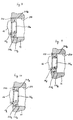
- Figure 8 illustrates a second embodiment of the present invention.
- radial ball bearing 31 of the first embodiment is replaced with angular contact ball bearing 310.
- Figure 9 illustrates a third embodiment of the present invention.
- radial ball bearing 31 of the first embodiment is replace with collared cylindrical roller bearing 320.
- Figure 10 illustrates a fourth embodiment of the present invention.
- radial ball bearing 31 of the first embodiment is replaced with circular cone roller bearing 330.
- each of the bearings 310, 320 and 330 is not symmetrical body with respect to a center plane perpendicular to the axis of each of the bearings, each of the bearings is forcibly inserted into large diameter portion 210a of central bore 210 so as to maintain that one certain axial end thereof faces the side wall of annular ridge 26a of drive shaft 26.
- a manner of disposing each of the bearings within large diameter portion 210a of central bore 210 and a manner of disposing small diameter portion 26a of drive shaft 26 within each of the bearings are similar to the manners of the first embodiment other than the above-mentioned manner so that an explanation thereof is omitted.
- an effect of each of the embodiments is similar to the effect of the first embodiment so that an explanation thereof is also omitted.
Landscapes
- Engineering & Computer Science (AREA)
- Mechanical Engineering (AREA)
- General Engineering & Computer Science (AREA)
- Compressors, Vaccum Pumps And Other Relevant Systems (AREA)
- Compressor (AREA)
- Control Of Positive-Displacement Pumps (AREA)
Applications Claiming Priority (2)
| Application Number | Priority Date | Filing Date | Title |
|---|---|---|---|
| JP108122/91 | 1991-04-15 | ||
| JP3108122A JPH04318291A (ja) | 1991-04-15 | 1991-04-15 | 容量可変型斜板式圧縮機 |
Publications (1)
| Publication Number | Publication Date |
|---|---|
| EP0510496A1 true EP0510496A1 (de) | 1992-10-28 |
Family
ID=14476487
Family Applications (1)
| Application Number | Title | Priority Date | Filing Date |
|---|---|---|---|
| EP92106456A Withdrawn EP0510496A1 (de) | 1991-04-15 | 1992-04-14 | Schiefscheibenverdichter mit variablem Hubmechanismus |
Country Status (7)
| Country | Link |
|---|---|
| US (1) | US5299918A (de) |
| EP (1) | EP0510496A1 (de) |
| JP (1) | JPH04318291A (de) |
| KR (1) | KR100206615B1 (de) |
| CN (1) | CN1030096C (de) |
| AU (1) | AU1472692A (de) |
| CA (1) | CA2066071C (de) |
Cited By (2)
| Publication number | Priority date | Publication date | Assignee | Title |
|---|---|---|---|---|
| EP0635640A1 (de) * | 1993-07-20 | 1995-01-25 | Kabushiki Kaisha Toyoda Jidoshokki Seisakusho | Lageranordnung zur Verwendung in einem Kompressor |
| FR2785646A1 (fr) * | 1998-11-11 | 2000-05-12 | Sanden Corp | Compresseur a dispositif d'ajustement du jeu axial de l'arbre |
Families Citing this family (5)
| Publication number | Priority date | Publication date | Assignee | Title |
|---|---|---|---|---|
| JP2000170654A (ja) | 1998-10-02 | 2000-06-20 | Toyota Autom Loom Works Ltd | 可変容量圧縮機 |
| KR100389013B1 (ko) * | 2000-01-11 | 2003-06-25 | 가부시키가이샤 도요다 지도숏키 | 피스톤식 압축기 및 그 조립방법 |
| JP4247538B2 (ja) * | 2001-09-28 | 2009-04-02 | 株式会社ヴァレオサーマルシステムズ | 圧縮機 |
| US7172393B2 (en) * | 2002-09-05 | 2007-02-06 | Sanden Corporation | Multi-cylinder compressors and methods for designing such compressors |
| KR101348835B1 (ko) * | 2011-02-08 | 2014-01-07 | 한라비스테온공조 주식회사 | 압축기 |
Citations (4)
| Publication number | Priority date | Publication date | Assignee | Title |
|---|---|---|---|---|
| FR770149A (fr) * | 1933-03-27 | 1934-09-08 | Perfectionnements apportés aux pompes ou moteurs à fluide | |
| GB685138A (en) * | 1950-02-10 | 1952-12-31 | Winget Ltd | Improvements in or relating to reciprocating pumps |
| US2713829A (en) * | 1946-09-17 | 1955-07-26 | Beacham Hydraulic Company Ltd | Hydraulic pump |
| US4848101A (en) * | 1986-03-19 | 1989-07-18 | Diesel Kiki Co., Ltd. | Method and system for controlling capacity of variable capacity wobble plate compressor |
Family Cites Families (8)
| Publication number | Priority date | Publication date | Assignee | Title |
|---|---|---|---|---|
| US2672819A (en) * | 1948-12-31 | 1954-03-23 | Schweizerische Lokomotiv | Expansible-chamber and positivedisplacement type pump of variable capacity |
| US2991723A (en) * | 1958-02-05 | 1961-07-11 | Gen Motors Corp | Wobble plate diaphragm pump |
| US3823557A (en) * | 1968-05-23 | 1974-07-16 | Wagenen N Van | Fluid motor |
| US4776260A (en) * | 1980-11-07 | 1988-10-11 | Vincze Alexander L | Constant pressure pump |
| US4492527A (en) * | 1983-02-17 | 1985-01-08 | Diesel Kiki Co., Ltd. (Japanese Corp.) | Wobble plate piston pump |
| US4553905A (en) * | 1984-05-09 | 1985-11-19 | Diesel Kiki Co., Ltd. | Variable capacity wobble plate compressor with high stability of capacity control |
| JPH02115577A (ja) * | 1988-10-24 | 1990-04-27 | Sanden Corp | 容量可変形揺動式圧縮機 |
| JPH0325868U (de) * | 1989-07-24 | 1991-03-18 |
-
1991
- 1991-04-15 JP JP3108122A patent/JPH04318291A/ja not_active Withdrawn
-
1992
- 1992-04-08 AU AU14726/92A patent/AU1472692A/en not_active Abandoned
- 1992-04-14 EP EP92106456A patent/EP0510496A1/de not_active Withdrawn
- 1992-04-14 KR KR1019920006166A patent/KR100206615B1/ko not_active Expired - Lifetime
- 1992-04-15 CN CN92102838.5A patent/CN1030096C/zh not_active Expired - Lifetime
- 1992-04-15 CA CA002066071A patent/CA2066071C/en not_active Expired - Fee Related
-
1993
- 1993-05-19 US US08/063,062 patent/US5299918A/en not_active Expired - Lifetime
Patent Citations (4)
| Publication number | Priority date | Publication date | Assignee | Title |
|---|---|---|---|---|
| FR770149A (fr) * | 1933-03-27 | 1934-09-08 | Perfectionnements apportés aux pompes ou moteurs à fluide | |
| US2713829A (en) * | 1946-09-17 | 1955-07-26 | Beacham Hydraulic Company Ltd | Hydraulic pump |
| GB685138A (en) * | 1950-02-10 | 1952-12-31 | Winget Ltd | Improvements in or relating to reciprocating pumps |
| US4848101A (en) * | 1986-03-19 | 1989-07-18 | Diesel Kiki Co., Ltd. | Method and system for controlling capacity of variable capacity wobble plate compressor |
Cited By (3)
| Publication number | Priority date | Publication date | Assignee | Title |
|---|---|---|---|---|
| EP0635640A1 (de) * | 1993-07-20 | 1995-01-25 | Kabushiki Kaisha Toyoda Jidoshokki Seisakusho | Lageranordnung zur Verwendung in einem Kompressor |
| US5586870A (en) * | 1993-07-20 | 1996-12-24 | Kabushiki Kaisha Toyoda Jidoshokki Seisakusho | Bearing structure used in a compressor |
| FR2785646A1 (fr) * | 1998-11-11 | 2000-05-12 | Sanden Corp | Compresseur a dispositif d'ajustement du jeu axial de l'arbre |
Also Published As
| Publication number | Publication date |
|---|---|
| KR100206615B1 (ko) | 1999-07-01 |
| US5299918A (en) | 1994-04-05 |
| CN1065906A (zh) | 1992-11-04 |
| CA2066071A1 (en) | 1992-10-16 |
| CA2066071C (en) | 1996-05-21 |
| CN1030096C (zh) | 1995-10-18 |
| JPH04318291A (ja) | 1992-11-09 |
| AU1472692A (en) | 1992-10-22 |
Similar Documents
| Publication | Publication Date | Title |
|---|---|---|
| EP0410453B1 (de) | Schmiervorrichtung für eine Kolbenanordnung in einem Schiefscheibenverdichter | |
| EP0318316B1 (de) | Schiefscheibenverdichter mit Vorrichtung zur Hubveränderung | |
| US5094589A (en) | Slant plate type compressor with variable displacement mechanism | |
| EP0635640B1 (de) | Lageranordnung zur Verwendung in einem Kompressor | |
| EP0340024B1 (de) | Schiefscheibenverdichter mit variablem Hubmechanismus | |
| EP0405878B1 (de) | Schiefscheibenverdichter mit einer Vorrichtung zur Hubveränderung | |
| EP0623744B1 (de) | Schiefscheibenverdichter mit Vorrichtung zur Hubveränderung | |
| EP0372913B1 (de) | Schiefscheibenverdichter | |
| EP0653563B1 (de) | Schiefscheibenverdichter mit Vorrichtung zur Hubveränderung | |
| US6742439B2 (en) | Variable displacement compressor | |
| US5255569A (en) | Slant plate type compressor with variable displacement mechanism | |
| EP0499341B1 (de) | Taumelscheibenkompressor | |
| EP0510496A1 (de) | Schiefscheibenverdichter mit variablem Hubmechanismus | |
| EP0339897B1 (de) | Schiefscheibenverdichter mit veränderlichem Hubmechanismus |
Legal Events
| Date | Code | Title | Description |
|---|---|---|---|
| PUAI | Public reference made under article 153(3) epc to a published international application that has entered the european phase |
Free format text: ORIGINAL CODE: 0009012 |
|
| AK | Designated contracting states |
Kind code of ref document: A1 Designated state(s): DE FR GB IT SE |
|
| 17P | Request for examination filed |
Effective date: 19921020 |
|
| 17Q | First examination report despatched |
Effective date: 19940117 |
|
| STAA | Information on the status of an ep patent application or granted ep patent |
Free format text: STATUS: THE APPLICATION IS DEEMED TO BE WITHDRAWN |
|
| 18D | Application deemed to be withdrawn |
Effective date: 19940528 |