EP0510603B1 - Schleifkopf, insbesondere zum Schleifen von Marmor, Granit und Gestein im allgemeinen - Google Patents
Schleifkopf, insbesondere zum Schleifen von Marmor, Granit und Gestein im allgemeinen Download PDFInfo
- Publication number
- EP0510603B1 EP0510603B1 EP92106867A EP92106867A EP0510603B1 EP 0510603 B1 EP0510603 B1 EP 0510603B1 EP 92106867 A EP92106867 A EP 92106867A EP 92106867 A EP92106867 A EP 92106867A EP 0510603 B1 EP0510603 B1 EP 0510603B1
- Authority
- EP
- European Patent Office
- Prior art keywords
- grinder
- shaft
- grinder head
- tool
- teeth
- Prior art date
- Legal status (The legal status is an assumption and is not a legal conclusion. Google has not performed a legal analysis and makes no representation as to the accuracy of the status listed.)
- Expired - Lifetime
Links
- 238000005498 polishing Methods 0.000 title claims description 8
- 239000000463 material Substances 0.000 title claims description 7
- 239000004579 marble Substances 0.000 title claims description 5
- 239000010438 granite Substances 0.000 title claims description 4
- 239000004575 stone Substances 0.000 title claims description 4
- 230000008878 coupling Effects 0.000 claims description 9
- 238000010168 coupling process Methods 0.000 claims description 9
- 238000005859 coupling reaction Methods 0.000 claims description 9
- 230000010355 oscillation Effects 0.000 description 3
- 238000003754 machining Methods 0.000 description 2
- 230000007246 mechanism Effects 0.000 description 2
- 239000000919 ceramic Substances 0.000 description 1
- 238000010276 construction Methods 0.000 description 1
- 238000013016 damping Methods 0.000 description 1
- 238000010586 diagram Methods 0.000 description 1
- 230000037431 insertion Effects 0.000 description 1
- 238000003780 insertion Methods 0.000 description 1
- 230000000670 limiting effect Effects 0.000 description 1
Images

Classifications
-
- B—PERFORMING OPERATIONS; TRANSPORTING
- B24—GRINDING; POLISHING
- B24B—MACHINES, DEVICES, OR PROCESSES FOR GRINDING OR POLISHING; DRESSING OR CONDITIONING OF ABRADING SURFACES; FEEDING OF GRINDING, POLISHING, OR LAPPING AGENTS
- B24B41/00—Component parts such as frames, beds, carriages, headstocks
- B24B41/04—Headstocks; Working-spindles; Features relating thereto
- B24B41/047—Grinding heads for working on plane surfaces
- B24B41/0475—Grinding heads for working on plane surfaces equipped with oscillating abrasive blocks, e.g. mounted on a rotating head
Definitions
- the present invention relates to a grinder head, particularly for polishing marble, granite and stone materials in general.
- Grinder machines for polishing marble are therefore provided with a grinder head having a plurality of radial grinder tools.
- the grinder head rotates about a vertical axis while the grinder tools are oscillating about their horizontal axis.
- Each grinder tool generally has a curved working surface and therefore the tool working surface is substantially reduced to a constantly changing line.
- Grinder heads of this type have a very expensive construction due to the complicated lever mechanisms required for rotating the head and at the same time oscillating the grinder tools on the head.
- the aim of the present invention is to provide a rotating grinder head overcoming the above mentioned disadvantages and wherein the grinder tools are oscillating by means of far simpler and reliable mechanisms than those of the prior art.
- a grinder head particularly for polishing marble, granite and stone materials in general, having all the features defined in the attached claim 1.
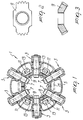
- the grinder head comprises a plurality of grinder tools 3 arranged radially on a case 5.
- Each grinder tool 3 has a shaft 7 having a gearwheel 9.
- Each gearwheel 9 is connected to two adjacent gearwheels of adjacent shafts so that all the shafts 7 oscillate together.
- At least one arm 11 is connected to one of shafts 7 and supports at least one wheel 13. Wheel 13 rolls along the undulated profile of a cam 15, which rotates in the same direction of the case 5 although at a different speed.
- FIGS. 2 and 3 show one of gearwheels 9 in greater detail.
- the different rotation speed of the cam 15, with respect to the case 5, causes the oscillation of the arm 11, rigidly associated with the shaft 7, and thus the partial and alternating rotation of the shaft itself.
- the grinding member is caused to oscillate because it is rigidly associated with the shaft, which is in turn connected to the wheel 13 which follows the shape of the cam.
- the grinder tools oscillate with an undulatory motion, each one in the direction opposite to the adjacent grinder tools.
- the oscillation of the grinder tools makes the grinding member to work with a cutting line which changes continuously, thus making it wear uniformly so as to obtain better polishing and excellent efficiency of said tool.
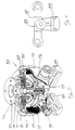
- FIGS. 4-7 show a grinder head 101 according to a further aspect of the invention, wherein a plate 120 is rigidly associated with the mandrel of the grinder machine.
- a bearing 102 is arranged between the central shaft 104, which rotates, and the upper part 106 of the case, which is fixed to the machine.
- the secondary shafts 103 are fixed on the upper part 106 of the case and constitute the shafts of gearwheels 105; the gearwheels 105 are actuated by the gearwheel 107 which is rigidly associated with the mandrel. Therefore, the gearwheel 107, by means of the gearwheels 105, transmits motion to the gearwheel 108 as well.
- the movable case 112 is connected to the lower slotted part of the main shaft by means of two concentric metallic rings 113 and 114 which are joined by a layer of rubber 115 and define an elastic rubber coupling.
- the planetary gearwheels 105 are divided into two parts having a different number of teeth.
- Figure 5 is a cutout view of the grinder head showing the lower case 112 which supports the grinding wheels 119.
- the undulatory motion of the slotted shafts 118 is transmitted to the grinder tools, and the slotted shafts are provided with two arms 117 which have, at their ends, wheels 116 which follow the profile 111a of the cam 111.
- FIG. 6 is a detail view of a grinder tool 119 which oscillates about the axis of the slotted shaft 118.
- the slotted shaft 118 has two arms 117 at whose ends two wheels 116 are arranged and follow the profile 111a of the cam 111.
- the slotted shafts are parallel to the working plane and are provided with two arms, at each end of which there is a wheel which is adapted to follow the profile of the internal cam.
- Rotary motion is transmitted to all the elements of the machine by the central shaft which is connected to the motor of the polishing machine and by adapted gearwheels.
- the shaft transmits its motion directly to the lower case which supports the grinding wheels and, by means of gearwheels, to the internal cam as well.
- the gearwheels rotate the cam with a speed which is different from the rotation speed of the shaft, because there is a small difference in the number of their teeth.
- the oscillation is produced by the profile of the cam, which forces a continuous lowering of an arm, causing the rise of the opposite arm.
- the central shaft meshes with a ring which is joined to a second outermost ring by means of the rubber coupling.
- the rubber coupling in addition to transmitting motion, has three other functions: damping start up; compensating slight differences in the level of the working surface; absorbing vibrations during operation.
- This coupling avoids the presence of any metallic connection between the motor shaft and the movable part.
- a ring is screwed on the lower end of the motor shaft, which is threaded, and supports all the movable parts of the head.
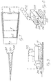
- FIGS 7-9 show a detail of the grinder tool of the grinder head according to the invention.
- Two or more guides with converging sides, suitable for supporting the tools, are defined on the tool holder, which is fixed to the arms of the rotating head.
- Said converging guides are arranged on different planes and are defined by sectional portions of the same cone; therefore they are arranged above one another and are shifted with respect to one another so that if their converging sides are ideally extended the meeting points do not coincide on a horizontal plane but are slightly offset.
- the abrasive-carrying tool which is inserted on these guides is also obtained from the same cone, and therefore can be inserted in any guide, arranging itself at different distances from the rotation axis.
- the tool is provided with an elongated central body with overlying protrusions which allows its insertion up to the innermost guide.
- the length of the tool is chosen so as to ensure perfect coupling in any position.
- the abrasive-carrying tool can thus be arranged in various positions and thus at various distances from the rotation axis of the head, defining, on the working surface, different annuli which are larger or smaller than the crown defined by the normal coupling. It is thus possible to perform, with the same tool, machining with different diameters depending on the guide in which said tool has been inserted.
- the working diameter is chosen according to the type, hardness and size of the material to be machined.
- the tool coupling for oscillating and non-oscillating rotating heads for machining ceramic, glassy and stone-like materials is provided with a plurality of guides in which the tool is inserted; said guides are mutually superimposed and shifted forward or backward with respect to one another so that the tool is inserted in a different position with respect to the center of rotation of the head.
- Figure 7 shows the three cones 201, 202 and 203 which are mutually offset and at different levels; the three guides 204, 205 and 206 are obtained from their profiles and are arranged at different levels on the same tool holder 207.
- Figure 8 is a view of the grinder tool 208, which is composed of an abrasive part 209 and of an upper abrasive-carrying part 210 which is suitable for being inserted on the holder 207 which is fixed to the arm 212 of the rotating head (indicated in broken lines).
- the upper part 210 is provided with a central body and with two protrusions 211 which are suitable for being inserted in the guides 204, 205 and 206.
- Figure 9 shows the various positions in which the tool 208 can work by inserting it in the various guides 204, 205 and 206; in the first position, the tool 208 is arranged on the innermost guide 204 and defines the smallest crown 213; in the second position, the tool 208 is inserted on the intermediate guide 205 and the crown 214 defined by the tool is the intermediate one; in the third position, the tool 208 is arranged on the lowermost guide 206 and defines the largest crown 215.
- the materials employed, as well as the dimensions, may be any according to the specific needs and the state of the art.
Landscapes
- Engineering & Computer Science (AREA)
- Mechanical Engineering (AREA)
- Finish Polishing, Edge Sharpening, And Grinding By Specific Grinding Devices (AREA)
Claims (4)
- Schleifkopf, insbesondere zum Schleifen von Marmor, Granit und Gestein im allgemeinen, mit einem drehbaren Gehäuse (5) zur Ankopplung an eine vertikale Spindel einer Schleifmaschine, das eine Vielzahl von radialen Schleifwerkzeugen (3) trägt, die jeweils auf einer Welle (7) befestigt sind, wobei wenigstens eine dieser Wellen starr mit wenigstens einem Arm (11) verbunden ist, der Arm einen Mitnehmernocken (13) trägt, der mit einer Steuerkurve (15) zusammenwirkt, um die Welle hin und her zu bewegen, dadurch gekennzeichnet, daß er Verbindungsmittel enthält, die geeignet sing, jede Welle mit wenigstens einer benachbarten Welle zu verbinden, wobei diese Verbindungsmittel ein Getriebeglied (9) enthalten, das eine zentrale, auf jede Welle nahe ihrem inneren Ende aufgesetzte Nabe und ein Paar von seitlichen Vorsprüngen besitzt, die sich von diametral gegenüberliegenden Seiten der Nabe aus, erstrecken, wobei jeder Vorsprung an seinem äußeren Ende einen Satz von Zähnen besitzt, der so angepaßt ist, daß er kontinuierlich in einen entsprechenden Satz von Zähnen eingreift, der zu einem benachbarten Getriebeglied gehört, wobei die Verbindung dergestalt ist, daß die Schneidlinien der Schleifwerkzeuge sich kontinuierlich verändern und dadurch einen gleichmäßigen Werkzeugverschleiß bedingen.
- Schleifkopf gemäß Anspruch 1, dadurch gekennzeichnet, daß die Zähne der mit Zähnen versehenen Vorsprünge konisch sind.
- Schleifkopf gemäß Anspruch 1, dadurch gekennzeichnet, daß jede Welle (118) zwei symmetrische Arme (117) besitzt, wobei beide mit einem Mitnehmer (116) versehen sind, der mit der Steuerkurve (111) zusammenwirkt.
- Schleifkopf gemäß Anspruch 1, dadurch gekennzeichnet, daß das Gehäuse (5) mit der vertikalen Spindel durch eine elastische Kupplung verbunden ist, die durch zwei konzentrische, durch eine Gummischicht (115) verbundene Metallringe (113,114) gebildet ist.
Applications Claiming Priority (2)
| Application Number | Priority Date | Filing Date | Title |
|---|---|---|---|
| ITPD910078 | 1991-04-23 | ||
| ITPD910078A IT1247256B (it) | 1991-04-23 | 1991-04-23 | Testa per la lucidatura di marmo, granito e materiali lapidei in genere con mole oscillanti. |
Publications (3)
| Publication Number | Publication Date |
|---|---|
| EP0510603A2 EP0510603A2 (de) | 1992-10-28 |
| EP0510603A3 EP0510603A3 (en) | 1993-01-13 |
| EP0510603B1 true EP0510603B1 (de) | 1996-01-10 |
Family
ID=11389550
Family Applications (1)
| Application Number | Title | Priority Date | Filing Date |
|---|---|---|---|
| EP92106867A Expired - Lifetime EP0510603B1 (de) | 1991-04-23 | 1992-04-22 | Schleifkopf, insbesondere zum Schleifen von Marmor, Granit und Gestein im allgemeinen |
Country Status (3)
| Country | Link |
|---|---|
| EP (1) | EP0510603B1 (de) |
| DE (1) | DE69207469D1 (de) |
| IT (1) | IT1247256B (de) |
Families Citing this family (6)
| Publication number | Priority date | Publication date | Assignee | Title |
|---|---|---|---|---|
| IT1262522B (it) * | 1993-05-25 | 1996-07-02 | Comes Srl | Testa per macchina lucidatrice con portasettori oscillanti. |
| IT1263400B (it) * | 1993-09-22 | 1996-08-05 | Luca Toncelli | Perfezionamenti a testa levigatrice e lucidatrice per graniti e pietresimili |
| IT1267682B1 (it) * | 1994-02-09 | 1997-02-07 | Simec Spa | Testa di lucidatura, particolarmente per lastre di marmo, granito, gres porcellanato ed altri materiali lapidei |
| IT1293124B1 (it) * | 1997-06-18 | 1999-02-11 | Giani & Grazzi Meccanica S R L | Testa levigatrice e lucidatrice per lastre lapidee |
| ITMI20040311U1 (it) * | 2004-06-24 | 2004-09-24 | Dario Toncelli | Testa di le igatura per materiali lapidei duri |
| IT202200013069A1 (it) * | 2022-06-21 | 2023-12-21 | Comes Srl | Testa lucidatrice |
Family Cites Families (2)
| Publication number | Priority date | Publication date | Assignee | Title |
|---|---|---|---|---|
| DE2015385C3 (de) * | 1970-04-01 | 1973-12-06 | Fickert & Winterling Kg Maschinenu. Schleifscheibenfabrik, 8590 Marktredwitz | Schleifkopf, insbesondere zum Schleifen von ebenen Flachen an Werk stucken aus Stein, Glas oder ahnlichen Werkstoffen |
| IT1224987B (it) * | 1988-07-27 | 1990-10-30 | C I G Consulenze Impianti Gasp | Testa a bracci oscillanti per la levigatura di marmi, graniti e simili |
-
1991
- 1991-04-23 IT ITPD910078A patent/IT1247256B/it active IP Right Grant
-
1992
- 1992-04-22 DE DE69207469T patent/DE69207469D1/de not_active Expired - Lifetime
- 1992-04-22 EP EP92106867A patent/EP0510603B1/de not_active Expired - Lifetime
Also Published As
| Publication number | Publication date |
|---|---|
| EP0510603A2 (de) | 1992-10-28 |
| ITPD910078A1 (it) | 1992-10-23 |
| IT1247256B (it) | 1994-12-12 |
| DE69207469D1 (de) | 1996-02-22 |
| EP0510603A3 (en) | 1993-01-13 |
| ITPD910078A0 (it) | 1991-04-23 |
Similar Documents
| Publication | Publication Date | Title |
|---|---|---|
| SU707512A3 (ru) | Устройство дл обработки наружных и внутренних поверхностей деталей многоугольной формы | |
| EP0178843A2 (de) | Flachschleifmaschine | |
| EP0510603A2 (de) | Schleifkopf, insbesondere zum Schleifen von Marmor, Granit und Gestein im allgemeinen | |
| JPS631472B2 (de) | ||
| KR100744074B1 (ko) | 석재용 연마기의 연마 헤드 | |
| EP0908271B1 (de) | Schleifkopf mit oszillierenden Werkzeugträgern | |
| BR9809841A (pt) | Cabeça polidora com segmentos abrasivos tendo movimento tangencial oscilante contìnuo, para materiais de granito, pedra dura ou cerâmica na forma de placas | |
| CA2320309C (en) | Machine tool and machine tool spindle and workpiece mounting-apparatus and grinding process | |
| CN106738388B (zh) | 一种用于小部件打孔及脆质材料扩孔的分离式钻头 | |
| JPH0569296A (ja) | 石材用研磨ヘツド | |
| US3877176A (en) | Apparatus for grinding bevel- or hyperboloid-shaped gears | |
| EP0301152B1 (de) | Schalttellermaschine mit elektrischer Steuerung | |
| JP2684329B2 (ja) | 角度方向及び縦方向に運動するダイヤモンドツールホルダー用の単一モーター駆動装置 | |
| US3891407A (en) | Method for grinding bevel- or hyperboloid-shaped gears | |
| WO2009090551A1 (en) | 'head for the treatment of stone and ceramic material | |
| RU2129946C1 (ru) | Устройство для абразивной обработки | |
| RU2100182C1 (ru) | Устройство для правки шлифовального круга | |
| KR200216644Y1 (ko) | 화강석 연마헤드 | |
| SU1207735A1 (ru) | Устройство дл сообщени осциллирующего движени шпинделю станка | |
| SU859128A1 (ru) | Хонинговальна головка | |
| SU1042904A1 (ru) | Многошпиндельна головка с регулируемым положением шпинделей | |
| RU2176586C1 (ru) | Устройство для абразивной обработки плоских поверхностей | |
| ES2225070T3 (es) | Cabezal de calibrado para materiales petreos. | |
| SU589107A1 (ru) | Устройство дл обработки асферических поверхностей | |
| JP3074424B2 (ja) | 環状部品の当り付け装置 |
Legal Events
| Date | Code | Title | Description |
|---|---|---|---|
| PUAI | Public reference made under article 153(3) epc to a published international application that has entered the european phase |
Free format text: ORIGINAL CODE: 0009012 |
|
| AK | Designated contracting states |
Kind code of ref document: A2 Designated state(s): DE ES FR IT NL PT |
|
| PUAL | Search report despatched |
Free format text: ORIGINAL CODE: 0009013 |
|
| AK | Designated contracting states |
Kind code of ref document: A3 Designated state(s): DE ES FR IT NL PT |
|
| 17P | Request for examination filed |
Effective date: 19930515 |
|
| 17Q | First examination report despatched |
Effective date: 19940714 |
|
| GRAA | (expected) grant |
Free format text: ORIGINAL CODE: 0009210 |
|
| AK | Designated contracting states |
Kind code of ref document: B1 Designated state(s): DE ES FR IT NL PT |
|
| PG25 | Lapsed in a contracting state [announced via postgrant information from national office to epo] |
Ref country code: NL Free format text: LAPSE BECAUSE OF FAILURE TO SUBMIT A TRANSLATION OF THE DESCRIPTION OR TO PAY THE FEE WITHIN THE PRESCRIBED TIME-LIMIT Effective date: 19960110 Ref country code: FR Effective date: 19960110 Ref country code: ES Free format text: THE PATENT HAS BEEN ANNULLED BY A DECISION OF A NATIONAL AUTHORITY Effective date: 19960110 |
|
| REF | Corresponds to: |
Ref document number: 69207469 Country of ref document: DE Date of ref document: 19960222 |
|
| ITF | It: translation for a ep patent filed | ||
| PG25 | Lapsed in a contracting state [announced via postgrant information from national office to epo] |
Ref country code: PT Effective date: 19960410 |
|
| PG25 | Lapsed in a contracting state [announced via postgrant information from national office to epo] |
Ref country code: DE Effective date: 19960411 |
|
| NLV1 | Nl: lapsed or annulled due to failure to fulfill the requirements of art. 29p and 29m of the patents act | ||
| EN | Fr: translation not filed | ||
| PLBQ | Unpublished change to opponent data |
Free format text: ORIGINAL CODE: EPIDOS OPPO |
|
| PLBI | Opposition filed |
Free format text: ORIGINAL CODE: 0009260 |
|
| PLBF | Reply of patent proprietor to notice(s) of opposition |
Free format text: ORIGINAL CODE: EPIDOS OBSO |
|
| 26 | Opposition filed |
Opponent name: NUOVE OFFICINE ANCORA S.R.L. Effective date: 19961010 |
|
| PLBF | Reply of patent proprietor to notice(s) of opposition |
Free format text: ORIGINAL CODE: EPIDOS OBSO |
|
| PLBF | Reply of patent proprietor to notice(s) of opposition |
Free format text: ORIGINAL CODE: EPIDOS OBSO |
|
| PLBQ | Unpublished change to opponent data |
Free format text: ORIGINAL CODE: EPIDOS OPPO |
|
| PLAB | Opposition data, opponent's data or that of the opponent's representative modified |
Free format text: ORIGINAL CODE: 0009299OPPO |
|
| PLBL | Opposition procedure terminated |
Free format text: ORIGINAL CODE: EPIDOS OPPC |
|
| R26 | Opposition filed (corrected) |
Opponent name: NUOVE OFFICINE ANCORA S.R.L. Effective date: 19961010 |
|
| PLBM | Termination of opposition procedure: date of legal effect published |
Free format text: ORIGINAL CODE: 0009276 |
|
| STAA | Information on the status of an ep patent application or granted ep patent |
Free format text: STATUS: OPPOSITION PROCEDURE CLOSED |
|
| 27C | Opposition proceedings terminated |
Effective date: 19981205 |
|
| PGFP | Annual fee paid to national office [announced via postgrant information from national office to epo] |
Ref country code: IT Payment date: 20060430 Year of fee payment: 15 |
|
| PG25 | Lapsed in a contracting state [announced via postgrant information from national office to epo] |
Ref country code: IT Free format text: LAPSE BECAUSE OF NON-PAYMENT OF DUE FEES Effective date: 20070422 |