EP0510656A2 - Evakuierungssystem und -verfahren - Google Patents
Evakuierungssystem und -verfahren Download PDFInfo
- Publication number
- EP0510656A2 EP0510656A2 EP92106974A EP92106974A EP0510656A2 EP 0510656 A2 EP0510656 A2 EP 0510656A2 EP 92106974 A EP92106974 A EP 92106974A EP 92106974 A EP92106974 A EP 92106974A EP 0510656 A2 EP0510656 A2 EP 0510656A2
- Authority
- EP
- European Patent Office
- Prior art keywords
- vacuum chamber
- valve
- pipeline
- main pump
- cooling
- Prior art date
- Legal status (The legal status is an assumption and is not a legal conclusion. Google has not performed a legal analysis and makes no representation as to the accuracy of the status listed.)
- Granted
Links
Images

Classifications
-
- C—CHEMISTRY; METALLURGY
- C23—COATING METALLIC MATERIAL; COATING MATERIAL WITH METALLIC MATERIAL; CHEMICAL SURFACE TREATMENT; DIFFUSION TREATMENT OF METALLIC MATERIAL; COATING BY VACUUM EVAPORATION, BY SPUTTERING, BY ION IMPLANTATION OR BY CHEMICAL VAPOUR DEPOSITION, IN GENERAL; INHIBITING CORROSION OF METALLIC MATERIAL OR INCRUSTATION IN GENERAL
- C23C—COATING METALLIC MATERIAL; COATING MATERIAL WITH METALLIC MATERIAL; SURFACE TREATMENT OF METALLIC MATERIAL BY DIFFUSION INTO THE SURFACE, BY CHEMICAL CONVERSION OR SUBSTITUTION; COATING BY VACUUM EVAPORATION, BY SPUTTERING, BY ION IMPLANTATION OR BY CHEMICAL VAPOUR DEPOSITION, IN GENERAL
- C23C14/00—Coating by vacuum evaporation, by sputtering or by ion implantation of the coating forming material
- C23C14/22—Coating by vacuum evaporation, by sputtering or by ion implantation of the coating forming material characterised by the process of coating
- C23C14/56—Apparatus specially adapted for continuous coating; Arrangements for maintaining the vacuum, e.g. vacuum locks
- C23C14/564—Means for minimising impurities in the coating chamber such as dust, moisture, residual gases
-
- B—PERFORMING OPERATIONS; TRANSPORTING
- B01—PHYSICAL OR CHEMICAL PROCESSES OR APPARATUS IN GENERAL
- B01J—CHEMICAL OR PHYSICAL PROCESSES, e.g. CATALYSIS OR COLLOID CHEMISTRY; THEIR RELEVANT APPARATUS
- B01J3/00—Processes of utilising sub-atmospheric or super-atmospheric pressure to effect chemical or physical change of matter; Apparatus therefor
-
- B—PERFORMING OPERATIONS; TRANSPORTING
- B01—PHYSICAL OR CHEMICAL PROCESSES OR APPARATUS IN GENERAL
- B01D—SEPARATION
- B01D8/00—Cold traps; Cold baffles
-
- B—PERFORMING OPERATIONS; TRANSPORTING
- B01—PHYSICAL OR CHEMICAL PROCESSES OR APPARATUS IN GENERAL
- B01J—CHEMICAL OR PHYSICAL PROCESSES, e.g. CATALYSIS OR COLLOID CHEMISTRY; THEIR RELEVANT APPARATUS
- B01J3/00—Processes of utilising sub-atmospheric or super-atmospheric pressure to effect chemical or physical change of matter; Apparatus therefor
- B01J3/006—Processes utilising sub-atmospheric pressure; Apparatus therefor
-
- Y—GENERAL TAGGING OF NEW TECHNOLOGICAL DEVELOPMENTS; GENERAL TAGGING OF CROSS-SECTIONAL TECHNOLOGIES SPANNING OVER SEVERAL SECTIONS OF THE IPC; TECHNICAL SUBJECTS COVERED BY FORMER USPC CROSS-REFERENCE ART COLLECTIONS [XRACs] AND DIGESTS
- Y10—TECHNICAL SUBJECTS COVERED BY FORMER USPC
- Y10S—TECHNICAL SUBJECTS COVERED BY FORMER USPC CROSS-REFERENCE ART COLLECTIONS [XRACs] AND DIGESTS
- Y10S417/00—Pumps
- Y10S417/901—Cryogenic pumps
Definitions
- the present invention relates to an evacuation system and a method therefor suitable for evacuation of, for example, a sputtering apparatus.
- a well-known type of evacuation system of a high vacuum sputtering apparatus is generally comprised of a cryopump connected to a sputtering chamber through a valve and auxiliary pumps for performing evacuation to obtain a pressure under which the cryopump can be actuated.
- the cryopump cools a baffle to extremely low temperature, approximately 20K (absolute temperature), by using a helium refrigerator, and absorbs and exhaust gas molecules. Since the baffle is cooled to an extremely low temperature, the cryopump is excellent in exhaust ability with respect to, particularly, water. Furthermore, since the cryopump is of a storage type, even if the sputtering apparatus is stopped due to some accident, there is little influence on the outside.
- the cryopump is widely used in a sputtering apparatus and so on.
- the storage type pump is required to be periodically regenerated after the exhaust is performed to more than a predetermined extent.
- a cryopump also has an evacuation ability with respect to argon, it is necessary to control the amount of exhausted argon gas by a valve operation or the like in a sputtering filming apparatus using argon gas.
- a cold head for cooling a baffle to approximately 150K by using a coolant is generally used to lower the pressure in a process chamber merely by increasing the exhaust amount of water molecules; or used as a cold trap to prevent oil molecules from flowing backward in an oil diffusion pump.
- the cold head is connected to the process chamber through a valve, and a main pump is directly connected to the downstream side of the cold head.
- the pumping speed with respect to gas molecules including water is made as high as possible in order to shorten the time required for continuing the exhaust to obtain a desired pressure.
- a vacuum pump since there is a limit to the pumping speed of a vacuum pump and a storage type pump such as a cryopump needs regeneration operations, the time which does not contribute to production is necessary in a semiconductor manufacturing apparatus such as a sputtering apparatus.
- the semiconductor manufacturing apparatus is required to restrict such loss of time.
- one apparatus removes the loss of time arising from the warm-up and stop of a cooling source by switching the temperature of a coolant of a cold trap in a short time.
- Such a kind of apparatus is disclosed in, for example, "A User's Guide to Vacuum Technology", John F. O'Hanlon.
- the object of the present invention is to provide an evacuation system and method suited to shorten the pumping time of a semiconductor manufacturing apparatus after the apparatus is exposed to the air for maintenance and so on, in particular, including evacuation to get a high vacuum region.
- the above object is achieved by proper application of the vacuum chamber leak method when a semiconductor manufacturing apparatus is exposed to the air, the evacuation method at subsequent vacuum system operation, and the rapid outgassing method of gas absorbed on the inner wall of a vacuum chamber.
- the moisture content of leakage gas is reduced to a great extent, and water molecules are thereby restrained from being absorbed on the inner wall of the vacuum chamber during the leakage.
- a means capable of rapidly heating the vacuum chamber is prepared so that baking of the vacuum chamber after getting a high vacuum region can be carried out in a short-time. At this time, since high vacuum and ultra-high vacuum pumps need the warm-up time, the evacuation system must be able to be operated in exposure to the air without being stopped.
- a cold trap is mounted and the temperature of the cold trap is kept a temperature at which it is difficult to absorb argon in sputtering. Furthermore, it is advantageous after baking to forcibly cool the vacuum chamber to a normal temperature for filming instead of waiting for the chamber to be naturally cooled. As described above, the aforementioned problem can be solved by integrating the above sequences in an optimal manner.
- a time required to get high and ultra-high vacuums is much longer than a time required to get low and medium vacuums from the air.
- an operation, called "baking" of evacuating while heating the vacuum chamber is generally employed.
- this baking is needed to form an ultra-high vacuum in a conventional semiconductor manufacturing apparatus, such as a sputtering apparatus, it takes a long time to warm the apparatus up again after exchanging of a target for new one, this resulting into many problems, for example, a decline in the working ratio. Therefore, it is essential to shorten the baking time in order to get an ultra-high vacuum in a short time.
- a vacuum chamber is provided with a pipeline for cooling in the present invention.
- a high speed exhaust pump is required to have a high pumping speed with respect to water.
- a cooling baffle whose temperature is set to that the pumping speed is low with respect to argon gas needed in sputtering and high with respect to water. The operation of a main pump is continued so as to shorten the warm-up time of main pump after the apparatus is opened to or communicated with the air for exhausting a target and so on, and a switching operation of a valve is linked to the operation of the main pump.
- an evacuation system comprising a main pump; an auxiliary pump disposed downstream of said main pump for operating said main pump; a cooling baffle disposed upstream of said main pump; a pipeline for linking said cooling baffle and a vacuum container through a valve; and a pipeline for linking said auxiliary pump and said vacuum container through a valve, wherein said cooling baffle has temperature control means for controlling the cooling temperature.
- said temperature control means includes a temperature detector for detecting the temperature of said cooling baffle and a control device for controlling the degree of opening of a control valve formed in an inlet tube for inserting a cooling medium into said cooling baffle therethrough in response to a signal from said temperature detector.
- the evacuation system further comprises a main pump; an auxiliary pump disposed downstream of said main pump for operating said main pump; a cooling baffle disposed upstream of said main pump; a pipeline for linking said cooling baffle and a vacuum chamber through a valve; and a pipeline for linking said auxiliary pump and said vacuum container through a valve, wherein a cooling temperature of said cooling baffle is controlled in accordance with the kind of gas supplied to said vacuum chamber.
- argon gas is supplied to said vacuum chamber and the cooling temperature of said cooling baffle is controlled so as to be within a range from 90K to 144 K.
- the evacuation system comprises in accordance with the invention a main pump; an auxiliary pump disposed downstream of said main pump for operating said main pump; a cooling baffle disposed upstream of said main pump; a pipeline for linking said cooling baffle and a vacuum chamber through a valve; and a pipeline for linking said auxiliary pump and said vacuum chamber through a valve, wherein a valve is interposed between said main pump and said cooling baffle and a pipeline is disposed between said valve and said main pump and connected to said vacuum chamber through a valve.
- the evacuation system comprises a main pump; an auxiliary pump disposed downstream of said main pump for operating said main pump; a cooling baffle disposed upstream of said main pump; a pipeline for linking said cooling baffle and a vacuum chamber through a valve; and a pipeline for linking said auxiliary pump and said vacuum chamber through a valve, wherein a valve is interposed between said main pump and said cooling baffle, a pipeline connected to said vacuum chamber is disposed between said valve and said main pump, two valves are disposed in parallel in said pipeline, and a pipeline connected to said auxiliary pump through a valve is interposed between said two valves.
- a pipeline for introducing a medium into said vacuum chamber to heat or cool said vacuum chamber is mounted and formed with a switch valve for switching a heating medium and a cooling medium to be introduced.
- said vacuum chamber is provided with means for heating said vacuum chamber and an inlet tube for introducing a cooling medium to cool said vacuum chamber.
- the evacuation system comprises a leakage valve which is connected to said vacuum valve, and a tube connected to said leakage valve which is cooled by a cooling medium of said cooling baffle.
- the invention extends further to an evacuation method of an evacuation system comprising a main pump, an auxiliary pump disposed downstream of said main pump for operating said main pump, a cooling baffle disposed upstream of said main pump, a pipeline for linking said cooling baffle and a vaccum chamber through a valve, and a pipeline for linking said auxiliary pump and said vacuum chamber through a valve, said method comprising the steps of separating said cooling baffle, said main pump and said auxiliary pump by closing said valves; operating said cooling baffle and said main pump in a normal state when evacuation is started in the state where only an evacuation system between said vacuum chamber and said auxiliary pump is open; evacuating said vacuum chamber by said auxiliary pump; and operating said valves to switch evacuation only by said auxiliary pump to evacuation by said auxiliary pump, said cooling baffle and said main pump.
- outgassing is conducted on said vacuum chamber after the evacuation by said auxiliary pump, said main pump and said cooling baffle is started, and then said vacuum chamber is rapidly cooled.
- all of said valves connected to said main pump are closed when said vacuum chamber is communicated with the air, the operations of said cooling baffle and said main pump are continued, and said vacuum chamber is communicated with the air through a leakage valve.
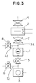
- Fig. 1 shows an embodiment of an evacuation system provided as the base of the present invention.
- a turbo-molecular pump 1 serving as a main pump is connected by a first pipeline 31 through a cooling baffle 2 with a vacuum chamber (not shown) which is a container to be evacuated, and an auxiliary pump 3 through a valve 5.
- An upstream valve 4 disposed upstream of the cooling baffle 2 in the first pipeline 31 is connected to the vacuum chamber.
- a gate valve or the like having a great conductance is preferable in order to prevent the pumping speed from decreasing.
- a valve 6 is connected to an inlet of the auxiliary pump 3 and to the vacuum chamber (not shown) by a second pipeline 32, only a part of which is shown.
- a coolant introducing pipe 21 for cooling the cooling baffle 2 has a control valve 22 for controlling the cooling temperature of the cooling baffle 2 by controlling the flow rate of a cooling medium.
- the degree of opening of the control valve 22 is controlled by a control device 23 in response to a signal from a temperature detector 24 for detecting the temperature of the cooling baffle 2.
- the cooling temperature of the cooling baffle 2 may be controlled by making the flow rate of the cooling medium constant and controlling the heating amount of a heating means mounted in the cooling baffle 2.
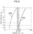
- the temperature of the cooling baffle 2 is set at 90K to 144K.
- vapor pressure curves with respect to argon and water are shown in Fig. 2.
- the boiling point of argon is 87.26K, and argon is vaporized above a temperature of 90K.
- the cooling baffle 2 Since a satisfactory vapor pressure of water is 10 ⁇ 6Pa, the cooling baffle 2 is cooled to 144K, judging from Fig. 2. In other words, a state in which water is sufficiently exhausted and argon is not exhausted is formed by keeping the temperature of the cooling baffle 2 in the shaded portion shown in Fig. 2. Since argon is exhausted by the turbo-molecular pump 1 serving as a main pump, it is not necessary to regenerate the cooling baffle 2 in the same manner as when a cryopump is regenerated. Therefore, the time is not lost by the regeneration of the cooling baffle 2, and thus a long operation time can be taken.
- turbo-molecular pump 1 If the exhaust by the auxiliary pump 3 is switched to the exhaust by the turbo-molecular pump 1 and a very rapid change arises in pressure, a wide pressure range or compound turbo-molecular pump is used as the turbo-molecular pump 1 in order to prevent the turbo-molecular pump 1 from being damaged. Since the wide pressure range turbo-molecular pump can operate even in a high pressure region, reliability is further increased.
- a time t when exhaustion is performed from the atmospheric pressure P0 to P of 13,3 Pa (0.1 Torr) at a pumping speed S (1000l/min.) by the auxiliary pump 3 is obtained from the following expression when a capacity V of the chamber is 100l: In other words, since 13,3 Pa (0.1 Torr) is obtained within approximately 1 minute, the above problem can be solved by using a proper pumping speed of the auxiliary pump 3 and a proper type of the main pump 1.
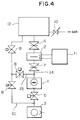
- a downstream valve 7 is interposed between the main pump 1 and the cooling baffle 2 in the first pipeline 31. Further, a third pipeline 33 with a valve 8 diverges from the inlet of the main pump 1, which third pipeline 33 is connected to the vacuum chamber (not shown). As upstream valve 4 and downstream valve 7, a gate valve having a great conductance is preferable in order to prevent the reduction of pumping speed.
- the system shown in Fig. 3 is connected to a vacuum chamber 12 by the first pipeline 31 at the upstream valve 4.
- the second pipeline 32 serving to perform exhaust by an auxiliary pump 3 from the air until a pressure capable of operating the main pump 1 is obtained is connected to the vacuum chamber 12 through a valve 9.
- the third pipeline 33 is connected to the second pipeline 32 between the valve 9 and the valve 6.
- the vacuum chamber 12 is provided with an additional pipe including an additional valve 10, preferably a leakage valve or a check valve. 11 represents control means as shown in Fig. 1, for example.
- the upstream valve 4, the downstream valve 7, the valve 5 and the valve 8 are closed.
- the turbo-molecular pump 1 and the cooling baffle 2 are put into the rated operational state beforehand. In this state, the valve 6 and the valve 9 are opened and the operation of the auxiliary pump 3 is started.
- the pressure in the vacuum chamber 12 becomes low enough to perform exhaust by the turbo-molecular pump 1
- the valve 6 is closed and the valves 5 and 8 are opened. Thereby the exhaust is conducted from a low vacuum region to medium and high vacuum regions.
- the upstream valve 4 and the downstream valve 7 are opened and the valves 8 and 9 are closed. Since the exhaust ability of the cooling baffle 2 is thereby added and, in particular, the exhaust ability with respect to water is increased, water as the main residual gas in the medium and high vacuum regions is exhausted at high speed.
- the temperature of the cooling baffle 2 is set at 90K to 144K as described above. If an ultra-high vacuum is formed and then gas, such as argon, is supplied, it is possible in this embodiment to avoid the route on the side of the cooling baffle 2. In other words, the argon gas can be exhausted in sputtering by closing the upstream valve 4 and the downstream valve 7 and by opening the valves 8 and 9 without using the cooling baffle 2. In such a case, it is effective to use a wide pressure range type turbo-molecular pump which is able to be used in a high pressure region as the main pump 1.
- auxiliary pump 3 If the exhaustion by the auxiliary pump 3 is switched to the exhaust by the turbo-molecular pump 1 and a very rapid change arises in pressure, in order to prevent the turbo-molecular pump 1 from being damaged, two valves 8 are mounted in parallel, one of the valves 8 is used as a pipeline with an orifice and first opened, and then the other valve is opened. Furthermore, as described above, the same effect is obtained when the main pump 1 is a wide pressure range type turbo-molecular pump.
- outgassing from the vacuum chamber 12 is not particularly taken into consideration.
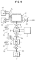
- the amount of gas desorbed from the vacuum chamber 12 is generally decreased proportional to a reciprocal number of time. It is effective to accelerate the outgassing so as to shorten the pumping time. For example, the amount of desorbed gas is increased by heating the vacuum chamber 12. The example will be explained with reference to Fig. 5.
- the evacuation system is the same as that in the above embodiment.
- a pipeline system 34 for circulating a heating medium is mounted to a vacuum chamber 12 so as to rapidly heat and cool the vacuum chamber 12.
- the vacuum chamber 12 shown in Fig. 5 has a double wall 13 through which the heating medium circulates around the vacuum chamber 12.
- a heating medium in a heating means 14 and a cooling medium in a cooling means 15 can be switched by operations of valves disposed in the pipeline system 34 as shown in Fig. 5. It is therefore possible to heat and cool the vacuum chamber 12 in a short time and to accelerate outgassing.
- a chamber In baking of an ordinary vacuum device, a chamber is heated by a heater and cooled by natural heat radiation after baking. Therefore, cooling takes a longer time than heating.
- baking heating of the vacuum chamber 12
- a heating medium for example, water.
- the amount of gas desorbed from the vacuum chamber 12 is decreased with cooling, and the pressure is lowered in a short time.
- the outgassing may be accelerated by using the outgassing method using discharge cleaning and radiation of ultraviolet rays, infrared rays and so on and the outgassing method using radiation of microwaves, and the short-time cooling may be carried out in the method of the present invention. In this case, the same advantageous effect can be obtained.
- leakage gas must be introduced through a cold trap or the like so as to include as little water as possible when the vacuum chamber 12 kept at a vacuum is opened to or communicated with the air so as to return the chamber to an atmosphere pressure state usually using N2 gas.
Landscapes
- Chemical & Material Sciences (AREA)
- Chemical Kinetics & Catalysis (AREA)
- Organic Chemistry (AREA)
- Metallurgy (AREA)
- Materials Engineering (AREA)
- Mechanical Engineering (AREA)
- Engineering & Computer Science (AREA)
- Compressors, Vaccum Pumps And Other Relevant Systems (AREA)
- Physical Vapour Deposition (AREA)
- Non-Positive Displacement Air Blowers (AREA)
- Degasification And Air Bubble Elimination (AREA)
- Devices For Use In Laboratory Experiments (AREA)
- Physical Deposition Of Substances That Are Components Of Semiconductor Devices (AREA)
Applications Claiming Priority (2)
| Application Number | Priority Date | Filing Date | Title |
|---|---|---|---|
| JP3095147A JPH04326943A (ja) | 1991-04-25 | 1991-04-25 | 真空排気システム及び排気方法 |
| JP95147/91 | 1991-04-25 |
Publications (3)
| Publication Number | Publication Date |
|---|---|
| EP0510656A2 true EP0510656A2 (de) | 1992-10-28 |
| EP0510656A3 EP0510656A3 (en) | 1993-08-04 |
| EP0510656B1 EP0510656B1 (de) | 1997-01-02 |
Family
ID=14129691
Family Applications (1)
| Application Number | Title | Priority Date | Filing Date |
|---|---|---|---|
| EP92106974A Expired - Lifetime EP0510656B1 (de) | 1991-04-25 | 1992-04-23 | Evakuierungssystem und -verfahren |
Country Status (5)
| Country | Link |
|---|---|
| US (1) | US5259735A (de) |
| EP (1) | EP0510656B1 (de) |
| JP (1) | JPH04326943A (de) |
| KR (1) | KR960003788B1 (de) |
| DE (1) | DE69216277T2 (de) |
Cited By (10)
| Publication number | Priority date | Publication date | Assignee | Title |
|---|---|---|---|---|
| DE19524609A1 (de) * | 1995-07-06 | 1997-01-09 | Leybold Ag | Vorrichtung zum raschen Evakuieren einer Vakuumkammer |
| EP0806499A1 (de) * | 1996-05-09 | 1997-11-12 | Sharp Kabushiki Kaisha | Verfahren und Vorrichtung zur Herstellung Halbleitern |
| DE19929519A1 (de) * | 1999-06-28 | 2001-01-04 | Pfeiffer Vacuum Gmbh | Verfahren zum Betrieb einer Mehrkammer-Vakuumanlage |
| DE10048210A1 (de) * | 2000-09-28 | 2002-05-08 | Singulus Technologies Ag | Vorrichtung und Verfahren zum Evakuieren einer ersten Kammer und einer zweiten Kammer |
| US7101155B2 (en) | 2002-05-31 | 2006-09-05 | The Boc Group Plc | Vacuum pumping system and method of controlling the same |
| WO2014072452A1 (fr) * | 2012-11-09 | 2014-05-15 | Centre National De La Recherche Scientifique | Dispositif de pompage, comprenant un ensemble de pompes en series et un element de commutation commun |
| CN103911589A (zh) * | 2014-04-18 | 2014-07-09 | 芜湖市德宝新材料股份有限公司 | 一种镀膜机真空冷却装置 |
| GB2579360A (en) * | 2018-11-28 | 2020-06-24 | Edwards Ltd | Multiple chamber vacuum exhaust system |
| GB2608365A (en) * | 2021-06-25 | 2023-01-04 | Thermo Fisher Scient Bremen Gmbh | Improvements relating to Time-of-Flight mass analysers |
| GB2628048A (en) * | 2021-06-25 | 2024-09-11 | Thermo Fisher Scient Bremen Gmbh | Improvements relating to Time-of-Flight mass analysers |
Families Citing this family (30)
| Publication number | Priority date | Publication date | Assignee | Title |
|---|---|---|---|---|
| US5733104A (en) * | 1992-12-24 | 1998-03-31 | Balzers-Pfeiffer Gmbh | Vacuum pump system |
| IL117775A (en) * | 1995-04-25 | 1998-10-30 | Ebara Germany Gmbh | Inhalation system with gas exhaust cleaner and operating process for it |
| JP4297975B2 (ja) * | 1996-03-20 | 2009-07-15 | ブルックス オートメーション インコーポレイテッド | クライオポンプのパージおよび低真空化による再生方法、クライオポンプおよび制御装置 |
| US6116032A (en) * | 1999-01-12 | 2000-09-12 | Applied Materials, Inc. | Method for reducing particulate generation from regeneration of cryogenic vacuum pumps |
| JP4027564B2 (ja) * | 2000-04-11 | 2007-12-26 | 株式会社荏原製作所 | 真空排気システム |
| FR2807951B1 (fr) * | 2000-04-20 | 2003-05-16 | Cit Alcatel | Procede et systeme de pompage des chambres de transfert d'equipement de semi-conducteur |
| US6327863B1 (en) | 2000-05-05 | 2001-12-11 | Helix Technology Corporation | Cryopump with gate valve control |
| FR2822200B1 (fr) * | 2001-03-19 | 2003-09-26 | Cit Alcatel | Systeme de pompage pour gaz a faible conductivite thermique |
| GB0214273D0 (en) * | 2002-06-20 | 2002-07-31 | Boc Group Plc | Apparatus for controlling the pressure in a process chamber and method of operating same |
| DE10348639B4 (de) | 2003-10-15 | 2009-08-27 | Von Ardenne Anlagentechnik Gmbh | Schleusensystem für eine Vakuumanlage |
| US7021888B2 (en) * | 2003-12-16 | 2006-04-04 | Universities Research Association, Inc. | Ultra-high speed vacuum pump system with first stage turbofan and second stage turbomolecular pump |
| GB0401396D0 (en) * | 2004-01-22 | 2004-02-25 | Boc Group Plc | Pressure control method |
| EP1721330A2 (de) * | 2004-03-05 | 2006-11-15 | Oi Corporation | Fokalebenen-detektorbaugruppe eines massenspektrometers |
| US7886692B2 (en) * | 2004-07-13 | 2011-02-15 | Delaval Holding Ab | Controllable vacuum source |
| US20070020115A1 (en) * | 2005-07-01 | 2007-01-25 | The Boc Group, Inc. | Integrated pump apparatus for semiconductor processing |
| JP4961701B2 (ja) * | 2005-09-14 | 2012-06-27 | パナソニック株式会社 | プラズマディスプレイパネルの製造方法 |
| KR100833648B1 (ko) * | 2007-05-25 | 2008-05-30 | 한국표준과학연구원 | 진공 레저버를 갖는 초고진공 배기시스템 |
| FR2940322B1 (fr) * | 2008-12-19 | 2011-02-11 | Alcatel Lucent | Procede de descente en pression dans un sas de chargement et de dechargement et equipement associe |
| JP5495547B2 (ja) * | 2008-12-25 | 2014-05-21 | キヤノン株式会社 | 処理装置、およびデバイス製造方法 |
| EP3502472B1 (de) * | 2009-12-24 | 2020-09-09 | Sumitomo Seika Chemicals Co., Ltd. | Abgasvibrationsunterdrückungsvorrichtung in einer doppelvakuumpumpe |
| FR2967219B1 (fr) * | 2010-11-05 | 2012-12-07 | Centre Nat Rech Scient | Installation de pompage pour l'obtention d'un vide pousse et procede de pompage mettant en oeuvre une telle installation |
| US9506478B2 (en) * | 2012-01-13 | 2016-11-29 | Edwards Limited | Vacuum system |
| JP2015074810A (ja) * | 2013-10-10 | 2015-04-20 | 日東電工株式会社 | スパッタ装置およびスパッタ装置のフィルムロールの交換方法 |
| JP6124776B2 (ja) | 2013-12-02 | 2017-05-10 | 住友重機械工業株式会社 | コールドトラップ |
| JP6150716B2 (ja) * | 2013-12-02 | 2017-06-21 | 住友重機械工業株式会社 | コールドトラップ |
| US10840077B2 (en) | 2018-06-05 | 2020-11-17 | Trace Matters Scientific Llc | Reconfigureable sequentially-packed ion (SPION) transfer device |
| CN109972099B (zh) * | 2019-05-10 | 2020-11-27 | 福建农林大学 | 一种制备片状氧化铁的方法 |
| JP7650633B2 (ja) | 2020-10-06 | 2025-03-25 | エドワーズ株式会社 | 真空排気システム |
| GB2606392B (en) * | 2021-05-07 | 2024-02-14 | Edwards Ltd | A fluid routing for a vacuum pumping system |
| CN113345979A (zh) * | 2021-05-25 | 2021-09-03 | 通威太阳能(成都)有限公司 | 一种真空机台快速复机方法 |
Family Cites Families (11)
| Publication number | Priority date | Publication date | Assignee | Title |
|---|---|---|---|---|
| NL129514C (de) * | 1965-10-27 | |||
| FR2014489A7 (en) * | 1968-07-02 | 1970-04-17 | Kernforschung Gmbh Ges Fuer | Uhv chamber for vapour deposition |
| US3536418A (en) * | 1969-02-13 | 1970-10-27 | Onezime P Breaux | Cryogenic turbo-molecular vacuum pump |
| US4089185A (en) * | 1974-10-31 | 1978-05-16 | Eckhard Kellner | High vacuum pump system |
| FR2380070A1 (fr) * | 1977-02-09 | 1978-09-08 | Cit Alcatel | Machine d'evaporation sous vide a cycle simplifie |
| US4285710A (en) * | 1978-09-18 | 1981-08-25 | Varian Associates, Inc. | Cryogenic device for restricting the pumping speed of selected gases |
| US4551197A (en) * | 1984-07-26 | 1985-11-05 | Guilmette Joseph G | Method and apparatus for the recovery and recycling of condensable gas reactants |
| US4667477A (en) * | 1985-03-28 | 1987-05-26 | Hitachi, Ltd. | Cryopump and method of operating same |
| US4679401A (en) * | 1985-07-03 | 1987-07-14 | Helix Technology Corporation | Temperature control of cryogenic systems |
| EP0250613B1 (de) * | 1986-06-23 | 1991-07-17 | Leybold Aktiengesellschaft | Kryopumpe und Verfahren zum Betrieb dieser Kryopumpe |
| US4722191A (en) * | 1986-09-17 | 1988-02-02 | Pennwalt Corporation | High vacuum pumping system |
-
1991
- 1991-04-25 JP JP3095147A patent/JPH04326943A/ja active Pending
-
1992
- 1992-03-23 KR KR1019920004741A patent/KR960003788B1/ko not_active Expired - Fee Related
- 1992-04-23 DE DE69216277T patent/DE69216277T2/de not_active Expired - Fee Related
- 1992-04-23 EP EP92106974A patent/EP0510656B1/de not_active Expired - Lifetime
- 1992-04-24 US US07/873,175 patent/US5259735A/en not_active Expired - Fee Related
Cited By (19)
| Publication number | Priority date | Publication date | Assignee | Title |
|---|---|---|---|---|
| EP0752531B1 (de) * | 1995-07-06 | 1998-11-04 | Leybold Aktiengesellschaft | Vorrichtung zum raschen Evakuieren einer Vakuumkammer |
| DE19524609A1 (de) * | 1995-07-06 | 1997-01-09 | Leybold Ag | Vorrichtung zum raschen Evakuieren einer Vakuumkammer |
| EP0806499A1 (de) * | 1996-05-09 | 1997-11-12 | Sharp Kabushiki Kaisha | Verfahren und Vorrichtung zur Herstellung Halbleitern |
| US6206969B1 (en) | 1996-05-09 | 2001-03-27 | Sharp Kabushiki Kaisha | Method and apparatus for fabricating semiconductor |
| DE19929519A1 (de) * | 1999-06-28 | 2001-01-04 | Pfeiffer Vacuum Gmbh | Verfahren zum Betrieb einer Mehrkammer-Vakuumanlage |
| EP1065385A3 (de) * | 1999-06-28 | 2001-04-11 | Pfeiffer Vacuum GmbH | Verfahren zum Betrieb einer Mehrkammer-Vakuumanlage |
| US6446651B1 (en) | 1999-06-28 | 2002-09-10 | Pfeiffer Vacuum Gmbh | Multi-chamber vacuum system and a method of operating the same |
| DE10048210B4 (de) * | 2000-09-28 | 2007-02-15 | Singulus Technologies Ag | Vorrichtung und Verfahren zum Einschleusen eines Werkstücks über eine Vorvakuumkammer in eine Hochvakuumkammer und deren Verwendung |
| DE10048210A1 (de) * | 2000-09-28 | 2002-05-08 | Singulus Technologies Ag | Vorrichtung und Verfahren zum Evakuieren einer ersten Kammer und einer zweiten Kammer |
| US7101155B2 (en) | 2002-05-31 | 2006-09-05 | The Boc Group Plc | Vacuum pumping system and method of controlling the same |
| WO2014072452A1 (fr) * | 2012-11-09 | 2014-05-15 | Centre National De La Recherche Scientifique | Dispositif de pompage, comprenant un ensemble de pompes en series et un element de commutation commun |
| FR2998010A1 (fr) * | 2012-11-09 | 2014-05-16 | Centre Nat Rech Scient | Dispositif de pompage, comprenant un ensemble de pompes en series et un element de commutation commun |
| CN103911589A (zh) * | 2014-04-18 | 2014-07-09 | 芜湖市德宝新材料股份有限公司 | 一种镀膜机真空冷却装置 |
| GB2579360A (en) * | 2018-11-28 | 2020-06-24 | Edwards Ltd | Multiple chamber vacuum exhaust system |
| US11933284B2 (en) | 2018-11-28 | 2024-03-19 | Edwards Limited | Multiple chamber vacuum exhaust system |
| GB2608365A (en) * | 2021-06-25 | 2023-01-04 | Thermo Fisher Scient Bremen Gmbh | Improvements relating to Time-of-Flight mass analysers |
| GB2628048A (en) * | 2021-06-25 | 2024-09-11 | Thermo Fisher Scient Bremen Gmbh | Improvements relating to Time-of-Flight mass analysers |
| GB2608365B (en) * | 2021-06-25 | 2024-11-27 | Thermo Fisher Scient Bremen Gmbh | Improvements relating toTime-of-Flight mass analysers |
| US12592373B2 (en) | 2021-06-25 | 2026-03-31 | Thermo Fisher Scientific (Bremen) Gmbh | Time-of-flight mass analysers |
Also Published As
| Publication number | Publication date |
|---|---|
| KR960003788B1 (ko) | 1996-03-22 |
| EP0510656B1 (de) | 1997-01-02 |
| US5259735A (en) | 1993-11-09 |
| EP0510656A3 (en) | 1993-08-04 |
| JPH04326943A (ja) | 1992-11-16 |
| KR920020087A (ko) | 1992-11-20 |
| DE69216277T2 (de) | 1997-07-10 |
| DE69216277D1 (de) | 1997-02-13 |
Similar Documents
| Publication | Publication Date | Title |
|---|---|---|
| EP0510656A2 (de) | Evakuierungssystem und -verfahren | |
| JP2574586B2 (ja) | クライオポンプを再生する方法及びこの方法を実施するのに適したクライオポンプ | |
| US4679401A (en) | Temperature control of cryogenic systems | |
| US5513499A (en) | Method and apparatus for cryopump regeneration using turbomolecular pump | |
| EP0919722B1 (de) | Regeneration einer Kryopumpe | |
| JP2631827B2 (ja) | 水蒸気クライオポンプ | |
| US5465584A (en) | Cryopump | |
| KR950007481B1 (ko) | 진공처리장치 | |
| US20070125112A1 (en) | Method and apparatus for regeneration water | |
| US4485631A (en) | Method and apparatus for rapidly regenerating a self-contained cryopump | |
| JPH06346848A (ja) | クライオポンプの再生方法及び真空排気系 | |
| US4860546A (en) | Vacuum system with molecular flow line | |
| JPH1047245A (ja) | 真空排気装置 | |
| JP2708569B2 (ja) | 真空装置の脱ガス方法及び脱ガス装置 | |
| JP3699159B2 (ja) | 核融合装置の真空排気システム | |
| JP3550616B2 (ja) | 冷凍設備に封入されている冷媒の回収方法、および、同回収装置 | |
| JP3424940B2 (ja) | ターボ分子ポンプによる排気方法及び装置 | |
| JPH05195952A (ja) | クライオパネル装置 | |
| JPH0774635B2 (ja) | 真空排気装置 | |
| JPH0770733A (ja) | 半導体製造装置及び真空排気方法 | |
| JP2674591B2 (ja) | 真空処理装置の運転方法 | |
| JP2012509442A (ja) | 排気系が組み込まれたプロセスチャンバ | |
| CN115628199A (zh) | 低温泵抽空装置及其抽空方法 | |
| JP3019471B2 (ja) | クライオポンプ | |
| JP2790936B2 (ja) | ターボ分子ポンプによる排気方法及び装置 |
Legal Events
| Date | Code | Title | Description |
|---|---|---|---|
| PUAI | Public reference made under article 153(3) epc to a published international application that has entered the european phase |
Free format text: ORIGINAL CODE: 0009012 |
|
| 17P | Request for examination filed |
Effective date: 19920423 |
|
| AK | Designated contracting states |
Kind code of ref document: A2 Designated state(s): DE FR GB |
|
| PUAL | Search report despatched |
Free format text: ORIGINAL CODE: 0009013 |
|
| AK | Designated contracting states |
Kind code of ref document: A3 Designated state(s): DE FR GB |
|
| 17Q | First examination report despatched |
Effective date: 19950523 |
|
| GRAG | Despatch of communication of intention to grant |
Free format text: ORIGINAL CODE: EPIDOS AGRA |
|
| GRAH | Despatch of communication of intention to grant a patent |
Free format text: ORIGINAL CODE: EPIDOS IGRA |
|
| GRAH | Despatch of communication of intention to grant a patent |
Free format text: ORIGINAL CODE: EPIDOS IGRA |
|
| GRAA | (expected) grant |
Free format text: ORIGINAL CODE: 0009210 |
|
| AK | Designated contracting states |
Kind code of ref document: B1 Designated state(s): DE FR GB |
|
| REF | Corresponds to: |
Ref document number: 69216277 Country of ref document: DE Date of ref document: 19970213 |
|
| ET | Fr: translation filed | ||
| PLBE | No opposition filed within time limit |
Free format text: ORIGINAL CODE: 0009261 |
|
| STAA | Information on the status of an ep patent application or granted ep patent |
Free format text: STATUS: NO OPPOSITION FILED WITHIN TIME LIMIT |
|
| 26N | No opposition filed | ||
| PGFP | Annual fee paid to national office [announced via postgrant information from national office to epo] |
Ref country code: FR Payment date: 19980216 Year of fee payment: 7 |
|
| PGFP | Annual fee paid to national office [announced via postgrant information from national office to epo] |
Ref country code: GB Payment date: 19980409 Year of fee payment: 7 |
|
| PGFP | Annual fee paid to national office [announced via postgrant information from national office to epo] |
Ref country code: DE Payment date: 19980629 Year of fee payment: 7 |
|
| PG25 | Lapsed in a contracting state [announced via postgrant information from national office to epo] |
Ref country code: GB Free format text: LAPSE BECAUSE OF NON-PAYMENT OF DUE FEES Effective date: 19990423 |
|
| GBPC | Gb: european patent ceased through non-payment of renewal fee |
Effective date: 19990423 |
|
| PG25 | Lapsed in a contracting state [announced via postgrant information from national office to epo] |
Ref country code: FR Free format text: LAPSE BECAUSE OF NON-PAYMENT OF DUE FEES Effective date: 19991231 |
|
| REG | Reference to a national code |
Ref country code: FR Ref legal event code: ST |
|
| PG25 | Lapsed in a contracting state [announced via postgrant information from national office to epo] |
Ref country code: DE Free format text: LAPSE BECAUSE OF NON-PAYMENT OF DUE FEES Effective date: 20000201 |