EP0510733A2 - Support moteur pour centrifugeuse - Google Patents
Support moteur pour centrifugeuse Download PDFInfo
- Publication number
- EP0510733A2 EP0510733A2 EP92112616A EP92112616A EP0510733A2 EP 0510733 A2 EP0510733 A2 EP 0510733A2 EP 92112616 A EP92112616 A EP 92112616A EP 92112616 A EP92112616 A EP 92112616A EP 0510733 A2 EP0510733 A2 EP 0510733A2
- Authority
- EP
- European Patent Office
- Prior art keywords
- columns
- axis
- mounting apparatus
- mount
- accommodated
- Prior art date
- Legal status (The legal status is an assumption and is not a legal conclusion. Google has not performed a legal analysis and makes no representation as to the accuracy of the status listed.)
- Withdrawn
Links
Images


Classifications
-
- B—PERFORMING OPERATIONS; TRANSPORTING
- B04—CENTRIFUGAL APPARATUS OR MACHINES FOR CARRYING-OUT PHYSICAL OR CHEMICAL PROCESSES
- B04B—CENTRIFUGES
- B04B9/00—Drives specially designed for centrifuges; Arrangement or disposition of transmission gearing; Suspending or balancing rotary bowls
- B04B9/12—Suspending rotary bowls ; Bearings; Packings for bearings
Definitions
- the present invention reiates to a mounting apparatus and in particular to a mounting apparatus for a motor used in a centrifuge instrument.
- the rotating member, or rotor forms part of a system that includes a motor or other source of motive energy, a drive shaft, and a rotor mounting device called a spud disposed at the upper end of the shaft on which the rotor is received.
- a motor or other source of motive energy e.g., a motor or other source of motive energy
- a drive shaft e.g., a motor or other source of motive energy
- a spud disposed at the upper end of the shaft on which the rotor is received.
- Violent motion and vibration are imparted to the rotor and the drive as it reaches the critical speed. However, once the critical speed is reached the vibration is significantly decreased.
- the drive is provided with some form of compliance mechanism which accommodates the forces imposed on the system as the rotor approaches and passes through its critical speed.
- centrifuge drives have developed along two distinct paths related to the use of such drives in different centrifuge rotational speed regimes.
- the drives for so-called lower speed centrifuges i.e., those having a speed less than twenty thousand revolutions per minute
- rigid shafts that are either directly coupled to a drive motor or are belt driven.
- Any compliance required for the stable operation of the instrument is achieved by the use of elastomeric "shock" mounts.
- Design of drives for higher speed instruments using such mounts is difficult since the dynamics of the system is influenced by the entire mass supported by the shock mounts, and not merely the rotor mass.
- Simple shock mounts cannot be used at higher speeds because of their low lateral and torsional stiffness compared to their pivot or moment stiffness.
- the moment stiffness is dependent on compression or extension of the elastic shock mount whereas the lateral and torsional stiffness are determined by shear of the elastic mount.
- the shear stiffness is usually only one third of the compressive stiffness. For this reason it is difficult to design critical speed out of the operating range from these three vibration modes.
- United States Patent 4,511,350 (Romanauskas) relates to a suspension system for a centrifuge. Additionally, there is known a flexural pivot system sold by Bendix Aerospace in which springs are used to accommodate forces.
- centrifuge drive that is able to allow significantly higher operating speed with simpler, more rugged, rigid shaft design. It is also believed advantageous to provide a drive having a motor mount that exhibits a relatively high lateral, vertical and torsional stiffness relative to the moment stiffness.
- the mounting apparatus of the present invention is defined by the features of claims 1, or 4, respectively.
- the mount of the invention includes two members, one of which defines at least one column having an axis parallel to the axis of the mount while the other of the members defines a plurality of columns the axes of which extend perpendicular to the axis of the mount.
- the columns are arranged such that a moment and a lateral force imposed on the members are accommodated by bending of predetermined ones of the columns while vertical and torsional forces are accommodated by compression or tension in at least predetermined ones of the columns.
- the inner member takes the form of an elongated pin that is arranged parallel to the axis of the mount while the outer member is generally cylindrical in shape and slotted to define a plurality of columns that lie in a plane that is generally perpendicular to the axis of the mount.
- a moment force is accommodated by bending of both the pin and the columns in the outer member. Lateral forces are accommodated primarily by bending of the columns in the outer member.
- a typical centrifuge system includes a drive motor mounted to the superstructure of the instrument, a shaft extending from the drive motor into the chamber of the instrument, a rotor mounting device, also known as a "spud", disposed at the upper end of the shaft, and a rotor mounted to the spud.
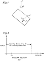
- the system is acted upon by forces in the vertical direction z, lateral (or shear) direction r, the torsion direction ⁇ and the moment (or pivot) direction ⁇ , where these various directions are as indicated on the coordinate system shown in Figure 1.
- the vertical forces act on the system along the z axis, the lateral forces act along any axis r lying in a plane P perpendicular to the z axis, the torsional forces ⁇ act angularly about the z axis, and the moment forces ⁇ a act angularly about any axis r.
- a motor mount 10' in accordance with an embodiment of the present invention the vertical (z) and torsional ( ⁇ ) forces are accommodated by placing columns in compression or tension, lateral (r) force is accommodated by placing columns with a relatively high moment of inertia inbending and moment force ( ⁇ ) is accommodated by placing columns with a reiatively low moment of inertia in bending.
- the stiffness coefficient K ⁇ is relatively much less than the stiffness coefficient associated with the other directions.
- the mount 10' includes a first, central, member 94 and a second, outer, member 96.
- the central member 94 is an elongated, pin-like member having an integral head portion 94H, a body portion 94B, a shoulder 94S and a tail portion 94T. Both the head 94H and the tail 94T are threaded.
- the head 94H is threadedly secured to a boss 12B located on the lower end bell of the motor 12.
- the exterior of the boss 12B is also threaded.
- the tail 94T is secured to the support plate 16 which in this instance is disposed below the motor 12 of the centrifuge.
- a nut 97 engages the protruded threaded portion of the tail 94T.
- the body 94B exhibits a generally circular cross section and defines the main structural portion of the inner member 94.
- the member 94 has an axis 94A therethrough that aligns with the axis 10A of the mount (and with the z axis).
- the outer member 96 is a hollow and generally cylindrical in shape.
- a flange 96F flares outwardly from one end of the member 96 and a lip 96L extends inwardly of the member 96 at the same end thereof.
- the interior surface at the opposite end of the member 96 is provided with threads 96T which engage the threads on the exterior of the boss 12B.
- the shoulder 96S of the inner member 94 clamps against the lip 96L of the outer member 96 to secure the same against the plate 16'.
- the outer member 96 is provided with cooperating pairs of upper and lower slots that extend through the walls of the member.
- the upper pair of siots is indicated by reference characters 98A and 98B and the lower pair of slots is indicated by the characters 102A and 102B.
- the upper and lower slots cooperate to define horizontal (as defined above), semi-circular columns 104A, 104B, 104C, and 104D therebetween.
- the columns 104 are equiangularly spaced with the axes of the columns lying in a plane perpendicular to the axis 10A of the mount 10'.
- Each of the columns 104 is generally rectangular in cross section and has a width dimension b (measured along the axis of the member 96) and a depth dimension h (measured radially of the member 96).
- the width dimension b is relatively small when compared to the depth dimension h.
- the axes of the semicircular columns lie on a common plane perpendicular to the axis of the mount. This plane intersects the axis 94A of the member 94 at the midpoint of the body portion 94B to define a pivot point 106 about which the mount 10' pivots.
- the second embodiment of the motor mount 10' in accordance with the present invention makes use of the well-known facts that a column in either compression or tension is inherently stiffer than the same column would be if loaded in bending and that a column with a rectangular cross section loaded in bending is stiffer when the load is imposed along its narrow dimension b as opposed to loading along the wider dimension h.
- the vertical column defined by the body portion 94B of the inner member 94 accommodates forces in the vertical (z) direction by being placed in either tension or compression.
- Torsional ( ⁇ ) forces are accommodated by placing all of the horizontal columns 104A through 104D in the outer member 96 in compression.
- Lateral (r) forces are imposed upon the columns 104A through 104D along the narrow faces b thereof.
- moment ( ⁇ ) forces are imposed on the columns along the relatively wider face h.
- either embodiment of the present invention will accommodate any moment by pivoting about the pivot point 90, 106 (as the case may be) and as such will act as the kinematic equivalent of a ball joint.
- the above-described embodiments of the invention are set forth in the context of a mount of a motor for a centrifuge instrument it should be understood that the mounting apparatus in accordance with the present invention may be used in any other environment.
Landscapes
- Centrifugal Separators (AREA)
- Motor Or Generator Frames (AREA)
Applications Claiming Priority (2)
| Application Number | Priority Date | Filing Date | Title |
|---|---|---|---|
| US17979688A | 1988-04-11 | 1988-04-11 | |
| US179796 | 1988-04-11 |
Related Parent Applications (2)
| Application Number | Title | Priority Date | Filing Date |
|---|---|---|---|
| EP89106026.1 Division | 1989-04-06 | ||
| EP19890106026 Division EP0337286A3 (fr) | 1988-04-11 | 1989-04-06 | Support moteur pour centrifugeuse |
Publications (2)
| Publication Number | Publication Date |
|---|---|
| EP0510733A2 true EP0510733A2 (fr) | 1992-10-28 |
| EP0510733A3 EP0510733A3 (en) | 1993-03-10 |
Family
ID=22658039
Family Applications (2)
| Application Number | Title | Priority Date | Filing Date |
|---|---|---|---|
| EP19890106026 Withdrawn EP0337286A3 (fr) | 1988-04-11 | 1989-04-06 | Support moteur pour centrifugeuse |
| EP19920112616 Withdrawn EP0510733A3 (en) | 1988-04-11 | 1989-04-06 | Motor mount for a centrifuge |
Family Applications Before (1)
| Application Number | Title | Priority Date | Filing Date |
|---|---|---|---|
| EP19890106026 Withdrawn EP0337286A3 (fr) | 1988-04-11 | 1989-04-06 | Support moteur pour centrifugeuse |
Country Status (2)
| Country | Link |
|---|---|
| EP (2) | EP0337286A3 (fr) |
| JP (1) | JPH0246144A (fr) |
Families Citing this family (1)
| Publication number | Priority date | Publication date | Assignee | Title |
|---|---|---|---|---|
| SE532905C2 (sv) * | 2008-09-22 | 2010-05-04 | Alfa Laval Corp Ab | Centrifugalseparator |
Family Cites Families (5)
| Publication number | Priority date | Publication date | Assignee | Title |
|---|---|---|---|---|
| DE198574C (fr) * | ||||
| FR1090004A (fr) * | 1953-07-22 | 1955-03-25 | Ressort | |
| GB1397172A (en) * | 1973-05-19 | 1975-06-11 | V Ni In K I Khim Mash | Resilient rotor support for centrifugal machines |
| AU503332B2 (en) * | 1976-04-05 | 1979-08-30 | Litton Industries Inc. | Flexure hinge assembly |
| IT1156346B (it) * | 1982-11-29 | 1987-02-04 | Pirelli | Dispositivo ammortizzatore |
-
1989
- 1989-04-06 EP EP19890106026 patent/EP0337286A3/fr not_active Withdrawn
- 1989-04-06 EP EP19920112616 patent/EP0510733A3/en not_active Withdrawn
- 1989-04-10 JP JP8817889A patent/JPH0246144A/ja active Pending
Also Published As
| Publication number | Publication date |
|---|---|
| EP0510733A3 (en) | 1993-03-10 |
| JPH0246144A (ja) | 1990-02-15 |
| EP0337286A3 (fr) | 1990-10-31 |
| EP0337286A2 (fr) | 1989-10-18 |
Similar Documents
| Publication | Publication Date | Title |
|---|---|---|
| US4242917A (en) | Isolation flexure for gyroscopes | |
| EP2292335B1 (fr) | Centrifugeuse avec un couplage permettant de maintenir la concentricité d' un arbre moteur | |
| US4201066A (en) | Flexible shaft construction for a high inertia centrifuge | |
| US3779451A (en) | Flexible shaft stabilizer | |
| US4182138A (en) | Rotary energy storage device | |
| WO1990004462A1 (fr) | Separateur et procede d'utilisation correspondant | |
| US5069413A (en) | Centrifuge motor mount having two slotted members | |
| EP0510733A2 (fr) | Support moteur pour centrifugeuse | |
| US3054284A (en) | Apparatus for testing torsional vibration dampers | |
| FUKUMA et al. | Fundamental research on gear noise and vibration:(6th report, generation mechanism of radial and axial vibration of spur gears) | |
| SU1511484A1 (ru) | Упругоцентробежна муфта | |
| SU620284A1 (ru) | Инерционный вибратор | |
| US3075404A (en) | Rotor support | |
| SU1482731A1 (ru) | Центрифуга | |
| SU1465743A1 (ru) | Установка дл испытани материалов на кручение | |
| SU1714429A1 (ru) | Инерционный нагружатель стенда дл испытани образцов на усталость | |
| SATO | Dynamic absorber using a hollow rotor partially filled with liquid | |
| SU1503894A1 (ru) | Вибровозбудитель | |
| RU1835500C (ru) | Установка дл испытаний материалов на усталость | |
| SU1397798A1 (ru) | Установка дл испытаний материалов на усталость | |
| SU915976A1 (ru) | Вибровозбудитель 1 | |
| SU448931A1 (ru) | Устройство дл сборки деталей | |
| SU1150306A1 (ru) | Вибрационное устройство | |
| RU2274493C1 (ru) | Привод вертикальных роторных машин | |
| SU1676669A1 (ru) | Вибровозбудитель |
Legal Events
| Date | Code | Title | Description |
|---|---|---|---|
| PUAI | Public reference made under article 153(3) epc to a published international application that has entered the european phase |
Free format text: ORIGINAL CODE: 0009012 |
|
| 17P | Request for examination filed |
Effective date: 19920723 |
|
| AC | Divisional application: reference to earlier application |
Ref document number: 337286 Country of ref document: EP |
|
| AK | Designated contracting states |
Kind code of ref document: A2 Designated state(s): DE FR GB IT |
|
| PUAL | Search report despatched |
Free format text: ORIGINAL CODE: 0009013 |
|
| AK | Designated contracting states |
Kind code of ref document: A3 Designated state(s): DE FR GB IT |
|
| STAA | Information on the status of an ep patent application or granted ep patent |
Free format text: STATUS: THE APPLICATION HAS BEEN WITHDRAWN |
|
| 18W | Application withdrawn |
Withdrawal date: 19940106 |