EP0510757A2 - Löschbares magnetooptisches Aufzeichnungsmedium und Verfahren zum gleichzeitigen Löschen aufgezeichneter Information und Aufzeichnen neuer Information - Google Patents
Löschbares magnetooptisches Aufzeichnungsmedium und Verfahren zum gleichzeitigen Löschen aufgezeichneter Information und Aufzeichnen neuer Information Download PDFInfo
- Publication number
- EP0510757A2 EP0510757A2 EP92201070A EP92201070A EP0510757A2 EP 0510757 A2 EP0510757 A2 EP 0510757A2 EP 92201070 A EP92201070 A EP 92201070A EP 92201070 A EP92201070 A EP 92201070A EP 0510757 A2 EP0510757 A2 EP 0510757A2
- Authority
- EP
- European Patent Office
- Prior art keywords
- magneto
- optical recording
- layer
- layers
- magnetization
- Prior art date
- Legal status (The legal status is an assumption and is not a legal conclusion. Google has not performed a legal analysis and makes no representation as to the accuracy of the status listed.)
- Ceased
Links
Images
Classifications
-
- G—PHYSICS
- G11—INFORMATION STORAGE
- G11B—INFORMATION STORAGE BASED ON RELATIVE MOVEMENT BETWEEN RECORD CARRIER AND TRANSDUCER
- G11B11/00—Recording on or reproducing from the same record carrier wherein for these two operations the methods are covered by different main groups of groups G11B3/00 - G11B7/00 or by different subgroups of group G11B9/00; Record carriers therefor
- G11B11/10—Recording on or reproducing from the same record carrier wherein for these two operations the methods are covered by different main groups of groups G11B3/00 - G11B7/00 or by different subgroups of group G11B9/00; Record carriers therefor using recording by magnetic means or other means for magnetisation or demagnetisation of a record carrier, e.g. light induced spin magnetisation; Demagnetisation by thermal or stress means in the presence or not of an orienting magnetic field
- G11B11/105—Recording on or reproducing from the same record carrier wherein for these two operations the methods are covered by different main groups of groups G11B3/00 - G11B7/00 or by different subgroups of group G11B9/00; Record carriers therefor using recording by magnetic means or other means for magnetisation or demagnetisation of a record carrier, e.g. light induced spin magnetisation; Demagnetisation by thermal or stress means in the presence or not of an orienting magnetic field using a beam of light or a magnetic field for recording by change of magnetisation and a beam of light for reproducing, i.e. magneto-optical, e.g. light-induced thermomagnetic recording, spin magnetisation recording, Kerr or Faraday effect reproducing
- G11B11/10502—Recording on or reproducing from the same record carrier wherein for these two operations the methods are covered by different main groups of groups G11B3/00 - G11B7/00 or by different subgroups of group G11B9/00; Record carriers therefor using recording by magnetic means or other means for magnetisation or demagnetisation of a record carrier, e.g. light induced spin magnetisation; Demagnetisation by thermal or stress means in the presence or not of an orienting magnetic field using a beam of light or a magnetic field for recording by change of magnetisation and a beam of light for reproducing, i.e. magneto-optical, e.g. light-induced thermomagnetic recording, spin magnetisation recording, Kerr or Faraday effect reproducing characterised by the transducing operation to be executed
- G11B11/10517—Overwriting or erasing
- G11B11/10519—Direct overwriting, i.e. performing erasing and recording using the same transducing means
- G11B11/10521—Direct overwriting, i.e. performing erasing and recording using the same transducing means using a single light spot
-
- G—PHYSICS
- G11—INFORMATION STORAGE
- G11B—INFORMATION STORAGE BASED ON RELATIVE MOVEMENT BETWEEN RECORD CARRIER AND TRANSDUCER
- G11B11/00—Recording on or reproducing from the same record carrier wherein for these two operations the methods are covered by different main groups of groups G11B3/00 - G11B7/00 or by different subgroups of group G11B9/00; Record carriers therefor
- G11B11/10—Recording on or reproducing from the same record carrier wherein for these two operations the methods are covered by different main groups of groups G11B3/00 - G11B7/00 or by different subgroups of group G11B9/00; Record carriers therefor using recording by magnetic means or other means for magnetisation or demagnetisation of a record carrier, e.g. light induced spin magnetisation; Demagnetisation by thermal or stress means in the presence or not of an orienting magnetic field
- G11B11/105—Recording on or reproducing from the same record carrier wherein for these two operations the methods are covered by different main groups of groups G11B3/00 - G11B7/00 or by different subgroups of group G11B9/00; Record carriers therefor using recording by magnetic means or other means for magnetisation or demagnetisation of a record carrier, e.g. light induced spin magnetisation; Demagnetisation by thermal or stress means in the presence or not of an orienting magnetic field using a beam of light or a magnetic field for recording by change of magnetisation and a beam of light for reproducing, i.e. magneto-optical, e.g. light-induced thermomagnetic recording, spin magnetisation recording, Kerr or Faraday effect reproducing
- G11B11/10502—Recording on or reproducing from the same record carrier wherein for these two operations the methods are covered by different main groups of groups G11B3/00 - G11B7/00 or by different subgroups of group G11B9/00; Record carriers therefor using recording by magnetic means or other means for magnetisation or demagnetisation of a record carrier, e.g. light induced spin magnetisation; Demagnetisation by thermal or stress means in the presence or not of an orienting magnetic field using a beam of light or a magnetic field for recording by change of magnetisation and a beam of light for reproducing, i.e. magneto-optical, e.g. light-induced thermomagnetic recording, spin magnetisation recording, Kerr or Faraday effect reproducing characterised by the transducing operation to be executed
- G11B11/10504—Recording
- G11B11/1051—Recording by modulating both the magnetic field and the light beam at the transducers
- G11B11/10513—Recording by modulating both the magnetic field and the light beam at the transducers one of the light beam or the magnetic field being modulated by data and the other by a clock or frequency generator
-
- G—PHYSICS
- G11—INFORMATION STORAGE
- G11B—INFORMATION STORAGE BASED ON RELATIVE MOVEMENT BETWEEN RECORD CARRIER AND TRANSDUCER
- G11B11/00—Recording on or reproducing from the same record carrier wherein for these two operations the methods are covered by different main groups of groups G11B3/00 - G11B7/00 or by different subgroups of group G11B9/00; Record carriers therefor
- G11B11/10—Recording on or reproducing from the same record carrier wherein for these two operations the methods are covered by different main groups of groups G11B3/00 - G11B7/00 or by different subgroups of group G11B9/00; Record carriers therefor using recording by magnetic means or other means for magnetisation or demagnetisation of a record carrier, e.g. light induced spin magnetisation; Demagnetisation by thermal or stress means in the presence or not of an orienting magnetic field
- G11B11/105—Recording on or reproducing from the same record carrier wherein for these two operations the methods are covered by different main groups of groups G11B3/00 - G11B7/00 or by different subgroups of group G11B9/00; Record carriers therefor using recording by magnetic means or other means for magnetisation or demagnetisation of a record carrier, e.g. light induced spin magnetisation; Demagnetisation by thermal or stress means in the presence or not of an orienting magnetic field using a beam of light or a magnetic field for recording by change of magnetisation and a beam of light for reproducing, i.e. magneto-optical, e.g. light-induced thermomagnetic recording, spin magnetisation recording, Kerr or Faraday effect reproducing
- G11B11/10582—Record carriers characterised by the selection of the material or by the structure or form
- G11B11/10584—Record carriers characterised by the selection of the material or by the structure or form characterised by the form, e.g. comprising mechanical protection elements
Definitions
- the invention relates to an erasable magneto-optical recording medium comprising a substrate on one side of which there is provided a first magneto-optical recording layer having a first Curie temperature and a second magneto-optical recording layer having a second Curie temperature, said magneto-optical layers having an easy axis of magnetization perpendicular to the plane of the layer, and superposed information bits in the form of magnetic domains being inscribable in both layers by a combination of irradiation with laser light and a modulated magnetic field.
- the invention also relates to a method of simultaneously erasing existing information and inscribing new information in such a magneto-optical recording medium.
- MO magneto-optical
- data are represented by magnetized domains or bits.
- the direction of magnetization of the domains extends perpendicularly to the plane of the MO-recording layer.
- the bits can be detected by means of the MO-effect in which the direction of polarization of polarized light changes as a function of the direction of magnetization of the domains when this light is reflected (Kerr-effect) or passed (Faraday-effect).
- the magnetized domains are obtained by locally heating the MO-recording layer by means of a focused laser light beam to a temperature above the Curie temperature of the material of the MO-recording layer. During cooling to a temperature below the Curie temperature, the magnetization is locally oriented according to the direction of an externally applied magnetic field and then frozen-in. This method is also termed thermomagnetic recording.
- a customary manner of inscribing information in a MO-recording layer consists in rotating a disc-shaped recording medium while a permanent external magnetic field and a laser light beam which is modulated according to the information to be recorded inscribe magnetic domains in the MO-recording layer.
- a disadvantage of said laser-modulation method is that the existing information cannot be directly overwritten with new information, but the existing information has to be erased first by using a permanent magnetic field and a continuous laser light beam.
- a suitable method of overwriting existing information with new information is magnetic field modulation (MFM).
- MFM magnetic field modulation
- the external magnetic field is modulated according to the information to be recorded, the focused laser light beam used having a constant power.
- the external magnetic field is generated by a magnet coil.
- MO-recording layer In the case of MO-recording using MFM, a MO-recording layer is desired whose direction of magnetization can change at weak magnetic fields, because this enables the dissipation of the magnet coil to be reduced and/or the distance of the magnet coil to the MO-recording layer to be enlarged. Technically, it is very difficult to generate a strong magnetic field having a high frequency (in the order of magnitude of 10 MHz).
- a disadvantage of the known MO-recording medium resides in the fact that the technology used for the manufacture of the exchange-coupled MO-layers is difficult to control.
- Said MO-layers are provided on a substrate by means of vacuum evaporation or sputtering.
- the exchange-coupling acts over only a few interatomic distances so that any contamination or oxidation of the first MO-layer substantially reduces the exchange-coupling with the second MO-layer.
- a further object of the invention is to provide a direct overwrite information recording method.
- this object is achieved by a MO-recording medium as described in the opening paragraph, which medium is characterized in that the MO-layers are separated from each other by an intermediate layer for the transfer of heat, in that the difference in Curie temperature between the MO-layers is 0-25° C, and in that the superposed domains have an equally oriented net direction of magnetization.
- the intermediate layer separating both MO-layers has a suitable heat conduction and is, for example, a metal layer such as aluminium. Said intermediate layer also precludes the exchange-coupling between the two MO-layers.
- both MO-layers will freeze magnetically at a different time, which is attained by a difference in Curie temperature between the MO-layers.
- the MO-layer having the highest Curie temperature is acting as the bias layer; the second MO-layer has a 0-25°C lower Curie temperature.
- both MO-layers are locally heated to a temperature above their Curie temperature. In said heated area the magnetization has disappeared. Meanwhile, said area is exposed to a magnetic field originating from a magnetic coil in the vicinity of said heated area.
- the heated area cools down to a temperature below the Curie temperature of the bias layer and the magnetization is oriented according to the direction of the external magnetic field and subsequently frozen-in.
- the corresponding area in the second MO-layer having the lower Curie temperature is subject to both the external magnetic field of the magnet coil and to the magnetic field originating from the area whose magnetization has just been frozen-in.
- the magnetization of this area is also frozen.
- the advantage of the use of a weak external magnetic field is that it enables the magnet coil to be reduced, thereby decreasing the dissipation of the coil and enabling said coil to be operated at higher frequencies.
- the distance between the coil and the MO-layer can be increased, so that the construction of the player is made simpler. Due to the relatively weak external field, not all the magnetic spins in the bias layer will be oriented in the direction of the external field; a part of the magnetic spins will still be oppositely oriented, yet, the net direction of magnetization is equal to that of the external magnetic field.
- the MO-layers contain domains, such that the domains of the first MO-layer (bias layer) adjoining the domains of the second MO-layer have the same direction of magnetization. Both MO-layers contain identical information.
- Such a MO-recording medium can be read from two sides, namely from the substrate side if the substrate is transparent to the wavelength of the laser light used, and from the opposite side (so-called air incident).
- Rare earth transition metal alloys such as GdTbFe and TbFeCo can be used as the material for the MO-layers.
- Multilayers such as Co/Pt or Co/Pd can also be used.
- a difference in Curie temperature can easily be achieved, for example, by changing the composition or the partial nitrogen pressure during the sputtering of such layers.
- the Curie temperature of such a MO-material is preferably selected in the temperature range 150-250°.
- the necessary thickness of the intermediate layer depends on, inter alia , the heat conduction coefficient of the material used. If aluminium is used, a suitable thickness is approximately 20 nm.
- the point of compensation of a MO-material is the temperature at which the magnetization is zero and at which the direction of magnetization above and below said temperature is different.
- the point of compensation is preferably selected close to room temperature, which has the additional advantage that the magnetization curve as a function of the temperature has a steep variation just below the Curie temperature, which results in a relatively large magnetic field of the bias layer.
- MO-layers having the same Curie temperature if the structure of the MO-recording medium behaves in a thermally asymmetric manner.
- the MO-layer will cool most rapidly on the side having the highest heat conduction and, thus, serve as the bias layer.
- a thermally symmetric MO-recording medium will behave thermally asymmetrically because the laser light is absorbed mainly in one MO-layer.
- the MO-layers are bounded by materials having a different heat conduction, such as the substrate and a protective lacquer, respectively.
- the idea is not limited to two MO-layers. If the bias layer is enclosed between two MO-layers having a Curie temperature below that of the bias layer, the bias layer will reduce the required field for both MO-layers.
- the layer having the highest Curie temperature then acts as the bias layer for the layer having the middle Curie temperature and both layers subsequently act as bias layers for the layer having the lowest Curie temperature.
- the layer becomes more complicated and thermally less sensitive.
- a suitable difference in Curie temperature is, for example, 8° C.
- the adverse effect of spot widening occurs in the MO-layer having the lowest Curie temperature because a certain domain size inscribed in the bias layer results in a larger domain size in the layer having the lowest Curie temperature.
- Exposure to the focused laser light beam is preferably carried out via the substrate.
- the usually disc-shaped substrate must be transparent to the wavelength of the laser light used.
- any dust particles or other impurities present on the surface of the substrate adversely affect the quality of recording and reading because said impurities are remote from the focal point of the objective used to focus the light beam on the MO-layers.
- the transparent substrate is manufactured from, for example, glass, quartz or a transparent synthetic resin such as polycarbonate or polymethyl methacrylate.
- the surface of the substrate at the side of the MO-layers may be provided with an optically scannable groove, a so-called servo track or guide track, which is generally spiral-shaped.
- a replication process to provide the groove in a separate synthetic resin layer applied to the substrate, which layer consists of, for example, a UV light-cured layer of acrylates.
- the MO-layer is applied on top of said layer.
- the outermost MO-layer is shielded from its surroundings by a protective layer of, for example, UV light-cured acrylate.
- Inorganic dielectric layers may be present between a MO-layer and the substrate and between the (second) MO-layer and the protective layer.
- Many of the layers used consist of metal nitride such as aluminium nitride and silicon nitride. Such layers also serve to protect the MO-layers.
- Amorphous rare earth transition metal alloys used as the material for the MO-layers can be obtained in several ways, such as vacuum evaporation, RE and DC diode and magnetron sputtering.
- a sputter process is used in which the pressure is increased from an initial value of less than approximately 10 ⁇ 6 mbar to 10 ⁇ 3 mbar during sputtering with an inert gas.
- a magnetic field may be used having a field strength of, for example, 160 kA/m (2000 Oe) which extends perpendicularly to the plane of deposition.
- the recorded domains or bits are read magneto-optically by means of a continuous, linearly polarized laser light beam of low intensity which is focused on the MO-layers.
- the plane of polarization of the light beam is rotated at the location of a bit through a certain angle which can be established and measured by means of a detector.
- the rotation of the plane of polarization takes place with both a reflected light beam, the rotation then being termed Kerr-rotation, and with a passed beam, in which case it is termed Faraday-rotation.
- the invention further relates to a method of simultaneously erasing existing information and inscribing new information (termed direct overwrite) in a disc-shaped MO-recording medium as described hereinbefore, and which recording medium also forms part of the present invention, in which method the magneto-optical recording medium is rotated and the magneto-optical recording layers are locally heated by exposure to a write spot which is moved diametrally across the medium and which originates from a laser light beam which is focused on the magneto-optical recording layers, while an external magnetic field which is modulated according to the information to be recorded is present at the location of the write spot and is oriented predominantly perpendicularly to the magneto-optical recording layers, so that locally the magnetization of the first magneto-optical layer having the highest Curie temperature is oriented in the direction of the external magnetic field whereas in an adjoining area of the second magneto-optical recording layer having the lowest Curie temperature the magnetization is zero, after which the magnetization in the first magneto-optical recording layer is frozen-in
- the linear velocity of the MO-recording medium is governed by the type of information which is recorded, such as audio, video or data information and is, for example, 1 to 20 m/s.
- the exposed areas of the MO-recording layers are heated to a temperature above or close to the Curie temperature, after which a magnetic domain or bit is formed in both MO-recording layers by cooling, said domain or bit having a direction of magnetization which corresponds to the external magnetic field.
- Said external magnetic field originates from a magnet coil which is modulated in accordance with the information to be recorded with a frequency in the MHz range.
- the bits formed have small diametral dimensions of maximally one or a few micrometers so that a high information density is obtained.
- the recorded information is read, as described hereinabove, by using linearly polarized laser light having a low power and reading is based on the magneto-optical effect (Kerr or Faraday effect).
- both MO-recording layers contain identical information, i.e. magnetically equally oriented superposed domains, so that the recording medium can be read from two sides (so-called air incident and substrate incident).
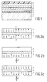
- Reference numeral 1 in Fig. 1 denotes a glass substrate.
- the substrate has the shape of a disc having a diameter of 12 cm and a thickness of 1.2 mm.
- the surface of substrate 1 is provided with a layer 2 of a UV light-cured acrylate synthetic resin in which a spiral-shaped groove (not shown) is formed by means of a replication process which is known per se .
- a dielectric AlN-layer 3 having a thickness of 80 nm is sputtered onto layer 2.
- a first MO-recording layer 4 having a thickness of 45 nm is sputtered onto layer 3.
- the Curie temperature of this layer is approximately 180° C.
- An aluminium layer 5 having a thickness of 20 nm is sputtered onto layer 4.
- a second MO-recording layer 6 having a thickness of 45 nm is sputtered onto layer 5.
- the Curie temperature of layer 6 is 8° C below that of layer 4.
- a dielectric AlN-layer 7 having a thickness of 80 nm is sputtered onto layer 6.
- Layer 7 is covered with an acrylate protective layer 8 which is cured by UV radiation.
- Fig. 2 shows the principle of direct overwrite according to the invention.
- Layer 4 is a part of the MO-recording layer having the highest Curie temperature
- layer 6 is a part of the MO-recording layer having the lowest temperature.
- Layer 5 is a part of the aluminium intermediate layer.
- the arrows in the layers indicate the directions of magnetization in the layers.
- Fig. 2a both layer 4 and layer 6 contain previously recorded information.
- Broken lines 11 and 11' indicate the respective domain walls. Parts of information bits are shown on the left and the right side of said domain walls.
- a focused laser light beam pulsed at a constant frequency is directed to the MO-recording layers so that the temperature locally rises to a level close to the Curie temperature of layer 4 and above the Curie temperature of layer 6.
- the magnetization of layer 6 disappears locally (Fig. 2b).
- An external magnetic field H which is relatively weak at that moment is directed, for example, downwards and is generated by a magnet coil which is modulated in accordance with the information to be recorded.
- the magnetization is locally largely directed downwards (see Fig. 2b) by said relatively weak external magnetic field H.
- the magnetization in layer 4 is frozen-in by cooling after which further cooling leads to a reduction of the temperature in layer 6 to below the Curie temperature of said layer.
- MO-layer 4 and MO-layer 6 contain identical information, so that the MO-recording medium can be read from two sides. Due to the weak external magnetic field H the magnetization of the information bits in layer 4 is not fully oriented according to the external magnetic field, consequently said MO-layer 4 will exhibit more noise during reading. In general this is no unsurmountable problem for data storage.
- MO-layer 4 (having the highest Curie temperature) has served as the bias layer.
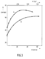
- the CNR is a measure of the quality of the MO-recording medium A CNR of 48 dB, measured at a carrier frequency of 1 MHz, a linear disc velocity of 5 m/s and a bandwidth of 30 kHz is sufficient for data-storage applications. Video-information requires 55 dB.
- the CNR is plotted as a function of the external magnetic field H for the type of MO-recording medium described.
- Curve A relates to MO-layer 6 (having the lowest Curie temperature)
- curve B relates to MO-layer 4 (having the highest Curie temperature).
- the difference in Curie temperature is 8° C.
- MO-layer 6 reaches the maximum value much sooner than MO-layer 4.
- Layer 4 reaches the maximum CNR at an external field of 50 kA/m (600 Oe), whereas layer 6 already reaches the maximum CNR at approximately 25 kA/m (300 Oe). This is caused by the fact that MO-layer 6 is subject to both the external field and the field of MO-layer 4.
Applications Claiming Priority (2)
| Application Number | Priority Date | Filing Date | Title |
|---|---|---|---|
| EP91200978 | 1991-04-24 | ||
| EP91200978 | 1991-04-24 |
Publications (2)
| Publication Number | Publication Date |
|---|---|
| EP0510757A2 true EP0510757A2 (de) | 1992-10-28 |
| EP0510757A3 EP0510757A3 (en) | 1993-06-09 |
Family
ID=8207625
Family Applications (1)
| Application Number | Title | Priority Date | Filing Date |
|---|---|---|---|
| EP19920201070 Ceased EP0510757A3 (en) | 1991-04-24 | 1992-04-15 | Erasable magneto-optical recording medium and method simultaneously erasing existing information and information and recording new information |
Country Status (3)
| Country | Link |
|---|---|
| US (1) | US5282095A (de) |
| EP (1) | EP0510757A3 (de) |
| JP (1) | JP3580830B2 (de) |
Families Citing this family (6)
| Publication number | Priority date | Publication date | Assignee | Title |
|---|---|---|---|---|
| WO1993013523A1 (fr) * | 1991-12-27 | 1993-07-08 | Fujitsu Limited | Procede d'enregistrement magneto-optique a ecrasement ameliorant le rapport porteuse/bruit, et appareil d'enregistrement a ecrasement utilise pour mettre en ×uvre ledite procede |
| US5359579A (en) * | 1992-07-10 | 1994-10-25 | Nec Corporation | Magneto-optical recording method and medium for recording three-value information |
| US5414678A (en) * | 1994-09-02 | 1995-05-09 | Minnesota Mining And Manufacturing Company | Magneto-optic recording medium having two recording layers, and drive for same |
| JP3354726B2 (ja) * | 1994-09-27 | 2002-12-09 | 松下電器産業株式会社 | 光磁気記録媒体及び再生方法 |
| US6228482B1 (en) | 1998-01-06 | 2001-05-08 | Imation Corp. | Magneto-optic recording medium with reduced demagnetizing field threshold |
| US9741927B2 (en) | 2014-04-10 | 2017-08-22 | Samsung Electronics Co., Ltd. | Method and system for providing magnetic junctions having a gradient in magnetic ordering temperature |
Family Cites Families (10)
| Publication number | Priority date | Publication date | Assignee | Title |
|---|---|---|---|---|
| GB2110459B (en) * | 1982-11-08 | 1985-08-14 | Kokusai Denshin Denwa Co Ltd | Magneto-optical recording system |
| JPS59215037A (ja) * | 1983-05-19 | 1984-12-04 | Brother Ind Ltd | 記録・再生装置の記録媒体 |
| US4922454A (en) * | 1984-10-30 | 1990-05-01 | Brother Kogyo Kabushiki Kaisha | Magneto-optical memory medium and apparatus for writing and reading information on and from the medium |
| JPH07105082B2 (ja) * | 1985-11-28 | 1995-11-13 | ソニー株式会社 | 光磁気記録媒体 |
| AU600576B2 (en) * | 1987-04-24 | 1990-08-16 | Sony Corporation | Thermomagnetic recording method applying power modulated laser on a magnetically coupled multi-layer structure of perpendicular anisotropy magnetic film |
| JP2828993B2 (ja) * | 1987-08-21 | 1998-11-25 | 株式会社東芝 | 光磁気記録媒体及びそれを用いた情報記録方法 |
| JP2630976B2 (ja) * | 1988-03-19 | 1997-07-16 | 富士通株式会社 | 光磁気記録媒体 |
| JP3078550B2 (ja) * | 1988-06-23 | 2000-08-21 | 株式会社東芝 | 光磁気記録方法及びそれに使用される光磁気記録媒体 |
| JP2830018B2 (ja) * | 1989-03-01 | 1998-12-02 | 株式会社ニコン | 光磁気記録媒体 |
| US5069984A (en) * | 1990-08-23 | 1991-12-03 | Eastman Kodak Company | Overwritable magnetooptical recording element including first and second magnetic layers, with one of which containing zirconium |
-
1992
- 1992-03-17 US US07/852,477 patent/US5282095A/en not_active Expired - Fee Related
- 1992-04-15 EP EP19920201070 patent/EP0510757A3/en not_active Ceased
- 1992-04-23 JP JP10452892A patent/JP3580830B2/ja not_active Expired - Fee Related
Also Published As
| Publication number | Publication date |
|---|---|
| JP3580830B2 (ja) | 2004-10-27 |
| US5282095A (en) | 1994-01-25 |
| EP0510757A3 (en) | 1993-06-09 |
| JPH05128610A (ja) | 1993-05-25 |
Similar Documents
| Publication | Publication Date | Title |
|---|---|---|
| US5623458A (en) | Method for reproducing information data recorded on a magneto-optical device having plural magnetic layers | |
| US5616428A (en) | Magnetooptical recording medium and information recording and reproducing methods using the recording medium | |
| US4753853A (en) | Double-layered magnetooptical recording medium | |
| JPH0235371B2 (de) | ||
| JPH06290496A (ja) | 光磁気記録媒体、再生方法および再生装置 | |
| EP0673026B1 (de) | Informations-Aufzeichnungsverfahren | |
| US5656384A (en) | Magnetooptical recording medium, method for producing the same, method for recording or reproducing information in or from the same | |
| US6248439B1 (en) | Magneto-optical recording medium and reproducing method for information recorder on the medium | |
| JPH08203141A (ja) | 光磁気記録媒体及びその再生方法 | |
| US5666346A (en) | Super-resolution magnetooptical recording medium using magnetic phase transition material, and method for reproducing information from the medium | |
| JPH06124500A (ja) | 光磁気記録媒体及び該媒体の再生方法 | |
| US5282095A (en) | Direct over-write magneto-optical recording medium having multiple recording layers, and method of recording new information by directly overwriting pre-existing recorded information on such medium | |
| US5398219A (en) | Magneto-optical recording medium with amorphous alloy film layers | |
| EP0530913B1 (de) | Magnetooptisches Aufzeichnungsmedium | |
| EP0668585B1 (de) | Verfahren und System zur Informationsaufzeichnung auf ein magnetooptisches Aufzeichnungsmedium | |
| JPH0341906B2 (de) | ||
| JP3354726B2 (ja) | 光磁気記録媒体及び再生方法 | |
| US5263015A (en) | Magneto-optical recording media and overwrite recording method using the same | |
| US7126886B2 (en) | Magneto-optical recording medium and method for producing the same | |
| JP3333389B2 (ja) | 光磁気情報記憶媒体およびその再生方法 | |
| USRE38501E1 (en) | Magnetooptical recording medium and information recording and reproducing methods using the recording medium | |
| JPH0729231A (ja) | 53dBを越えるオーバーライト可能な光磁気記録媒体 | |
| JPH07110971A (ja) | 光磁気記録媒体、光磁気記録媒体記録装置及び光磁気記録媒体再生装置 | |
| EP0510758A2 (de) | Verfahren zum thermomagnetischen Aufzeichnen und optischen Auslesen von Information | |
| JPH05182269A (ja) | 光磁気記録媒体及び光磁気記録方式、光磁気再生方式 |
Legal Events
| Date | Code | Title | Description |
|---|---|---|---|
| PUAI | Public reference made under article 153(3) epc to a published international application that has entered the european phase |
Free format text: ORIGINAL CODE: 0009012 |
|
| AK | Designated contracting states |
Kind code of ref document: A2 Designated state(s): DE FR GB |
|
| PUAL | Search report despatched |
Free format text: ORIGINAL CODE: 0009013 |
|
| AK | Designated contracting states |
Kind code of ref document: A3 Designated state(s): DE FR GB |
|
| 17P | Request for examination filed |
Effective date: 19931125 |
|
| 17Q | First examination report despatched |
Effective date: 19951009 |
|
| GRAG | Despatch of communication of intention to grant |
Free format text: ORIGINAL CODE: EPIDOS AGRA |
|
| STAA | Information on the status of an ep patent application or granted ep patent |
Free format text: STATUS: THE APPLICATION HAS BEEN REFUSED |
|
| 18R | Application refused |
Effective date: 19960826 |