EP0510763B1 - Luminaire - Google Patents
Luminaire Download PDFInfo
- Publication number
- EP0510763B1 EP0510763B1 EP19920201098 EP92201098A EP0510763B1 EP 0510763 B1 EP0510763 B1 EP 0510763B1 EP 19920201098 EP19920201098 EP 19920201098 EP 92201098 A EP92201098 A EP 92201098A EP 0510763 B1 EP0510763 B1 EP 0510763B1
- Authority
- EP
- European Patent Office
- Prior art keywords
- luminaire
- rotation
- axis
- flap
- interior
- Prior art date
- Legal status (The legal status is an assumption and is not a legal conclusion. Google has not performed a legal analysis and makes no representation as to the accuracy of the status listed.)
- Expired - Lifetime
Links
- 230000002093 peripheral effect Effects 0.000 claims description 6
- 230000008901 benefit Effects 0.000 description 4
- 230000001681 protective effect Effects 0.000 description 2
- 238000007789 sealing Methods 0.000 description 2
- 238000010276 construction Methods 0.000 description 1
- 230000000694 effects Effects 0.000 description 1
- 238000000034 method Methods 0.000 description 1
- 229920000515 polycarbonate Polymers 0.000 description 1
- 239000004417 polycarbonate Substances 0.000 description 1
- 239000012780 transparent material Substances 0.000 description 1
Images

Classifications
-
- F—MECHANICAL ENGINEERING; LIGHTING; HEATING; WEAPONS; BLASTING
- F21—LIGHTING
- F21V—FUNCTIONAL FEATURES OR DETAILS OF LIGHTING DEVICES OR SYSTEMS THEREOF; STRUCTURAL COMBINATIONS OF LIGHTING DEVICES WITH OTHER ARTICLES, NOT OTHERWISE PROVIDED FOR
- F21V19/00—Fastening of light sources or lamp holders
- F21V19/04—Fastening of light sources or lamp holders with provision for changing light source, e.g. turret
-
- F—MECHANICAL ENGINEERING; LIGHTING; HEATING; WEAPONS; BLASTING
- F21—LIGHTING
- F21S—NON-PORTABLE LIGHTING DEVICES; SYSTEMS THEREOF; VEHICLE LIGHTING DEVICES SPECIALLY ADAPTED FOR VEHICLE EXTERIORS
- F21S8/00—Lighting devices intended for fixed installation
- F21S8/08—Lighting devices intended for fixed installation with a standard
- F21S8/085—Lighting devices intended for fixed installation with a standard of high-built type, e.g. street light
- F21S8/086—Lighting devices intended for fixed installation with a standard of high-built type, e.g. street light with lighting device attached sideways of the standard, e.g. for roads and highways
-
- F—MECHANICAL ENGINEERING; LIGHTING; HEATING; WEAPONS; BLASTING
- F21—LIGHTING
- F21V—FUNCTIONAL FEATURES OR DETAILS OF LIGHTING DEVICES OR SYSTEMS THEREOF; STRUCTURAL COMBINATIONS OF LIGHTING DEVICES WITH OTHER ARTICLES, NOT OTHERWISE PROVIDED FOR
- F21V17/00—Fastening of component parts of lighting devices, e.g. shades, globes, refractors, reflectors, filters, screens, grids or protective cages
- F21V17/10—Fastening of component parts of lighting devices, e.g. shades, globes, refractors, reflectors, filters, screens, grids or protective cages characterised by specific fastening means or way of fastening
- F21V17/16—Fastening of component parts of lighting devices, e.g. shades, globes, refractors, reflectors, filters, screens, grids or protective cages characterised by specific fastening means or way of fastening by deformation of parts; Snap action mounting
- F21V17/162—Fastening of component parts of lighting devices, e.g. shades, globes, refractors, reflectors, filters, screens, grids or protective cages characterised by specific fastening means or way of fastening by deformation of parts; Snap action mounting the parts being subjected to traction or compression, e.g. coil springs
-
- F—MECHANICAL ENGINEERING; LIGHTING; HEATING; WEAPONS; BLASTING
- F21—LIGHTING
- F21V—FUNCTIONAL FEATURES OR DETAILS OF LIGHTING DEVICES OR SYSTEMS THEREOF; STRUCTURAL COMBINATIONS OF LIGHTING DEVICES WITH OTHER ARTICLES, NOT OTHERWISE PROVIDED FOR
- F21V3/00—Globes; Bowls; Cover glasses
-
- F—MECHANICAL ENGINEERING; LIGHTING; HEATING; WEAPONS; BLASTING
- F21—LIGHTING
- F21W—INDEXING SCHEME ASSOCIATED WITH SUBCLASSES F21K, F21L, F21S and F21V, RELATING TO USES OR APPLICATIONS OF LIGHTING DEVICES OR SYSTEMS
- F21W2131/00—Use or application of lighting devices or systems not provided for in codes F21W2102/00-F21W2121/00
- F21W2131/10—Outdoor lighting
- F21W2131/105—Outdoor lighting of arenas or the like
-
- F—MECHANICAL ENGINEERING; LIGHTING; HEATING; WEAPONS; BLASTING
- F21—LIGHTING
- F21W—INDEXING SCHEME ASSOCIATED WITH SUBCLASSES F21K, F21L, F21S and F21V, RELATING TO USES OR APPLICATIONS OF LIGHTING DEVICES OR SYSTEMS
- F21W2131/00—Use or application of lighting devices or systems not provided for in codes F21W2102/00-F21W2121/00
- F21W2131/10—Outdoor lighting
- F21W2131/109—Outdoor lighting of gardens
Definitions
- the present invention relates to a luminaire comprising a body with an orifice to allow access to a light source capable of being installed inside, and an element intended to close said orifice, element of which, in the closed position, the peripheral part is inside the body, means being provided for guiding said element according to a rotational movement whose axis of rotation is located inside the body, movement which moves said element inside from the body.
- Such a luminaire can be used for example for lighting gardens or public places, such as streets, station platforms, etc.
- a luminaire according to the preamble above is known from document GB-A-1,193,284.
- the luminaire described in this document comprises a spherical body and a concentric spherical closure element, which can rotate about an axis which passes through it and which allows the use of any intermediate position between opening and closing. With an element arranged in this way, the connection of the body with the periphery of the closure element is not sealed.
- the invention proposes to provide such a luminaire which has a good seal.
- the axis of rotation is placed at a distance from the element and means are provided for pressing elastically from inside the body this element against a seat formed by the periphery of the aforesaid orifice.
- This also has the advantage of offering easy access to the light source and also that there are no visible devices for fixing or holding the element, such as hinges or latches.
- the replacement of a lamp can also be done without tools, with the exception of a possible ladder.
- the body has substantially the shape of a sphere, said element has substantially the shape of a spherical cap.
- the rotation of said element is also advantageously about an axis of rotation which passes substantially through its own center of curvature.
- This axis also advantageously passes through the center of the sphere constituting the body.
- this element always remains close to the wall of the body and there is no lost space.
- the shape obtained provides a pleasant aesthetic effect.
- the said means for pressing and the said means for guiding are rotating parts which comprise a first and a second part, movable relative to each other with an elastic force which separates them from the one of the other, and to which the said element is fixed.
- a seal is provided at the periphery of the above-mentioned orifice.
- the body is made in one piece. This also has the advantage of guaranteeing an absolute tightness of the body.
- Figure 1 is a view from below of a luminaire according to the invention.
- FIG. 2 is a side view of a luminaire according to the invention, in section along the arrow D in FIG. 1.
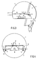
- Figure 3 is a side view of a light fixture according to the invention, cut in the same way as in Figure 2, but the light fixture is being opened.
- FIG. 4 is a front view of a luminaire according to the invention, in section along the arrow C in FIG. 2.
- the luminaire shown in FIG. 1 comprises a body 3, for example fixed to the end of the stem of a mast 1.
- this body is in the form of a sphere.
- This sphere is truncated to provide an orifice 12 in order to allow access to a light source, which is a lighting lamp 10 located inside.
- This orifice 12 can be closed by a movable closing element 2 which, in the case of a luminaire situated in height, is made of a transparent material, and which will be called "shutter" later.
- the peripheral part 13 of the protective flap 2 of the luminaire shown in FIG. 2 penetrates inside the body 3.
- This flap is in the form of a spherical cap substantially extending, in the closed position which is that shown, the shape of the sphere from the body. In this closed position, the peripheral part 13 of the shutter rests on the inside of the body.
- FIG. 3 shows how the flap 2 is retracted by a rotational movement symbolized by an arrow B, towards an open position located inside the body 3.
- FIG. 4 shows more completely the means for guiding said element according to a rotational movement in which the flap retracts towards the interior of the body: they consist of support parts 14, 15 on which is fixed (by means mechanical known indifferent) the shutter, at two points close to the edge of the shutter and symmetrical with respect to the vertical plane of symmetry of the whole of the luminaire.
- These parts 14, 15 are themselves connected to legs 6 articulated in rotation because they are each fixed to one end of a tube 5, held in rotation in a sleeve 8 and therefore rotating about an axis, indicated by the reference 16.
- Figures 2 or 3 show how the sleeve 8 is fixed to the body 3, for example by means of a support made of a rod 18 secured to a plate 17 fixed to the wall of the body, preferably near the point of attachment of the body to the mast 1.
- the joint can also be designed differently.
- the tube 5 may not exist, each of the two arms 6 (FIG. 4) then being supported by an individual articulation having the same axis.
- the protective shutter is provided with a circular seal 7 which is placed on the outer surface of the shutter, all along its periphery.
- this seal because of its thickness, keeps the flap at a small distance from the body during the movement shown in Figure 3 (arrow B), which prevents it from rubbing on the body and get scratched.
- the gasket 7 could also be attached to the body instead of being fixed to the shutter (while still being located in the same place when the luminaire is closed).
- the luminaire comprises a reflector 4 and the assembly of the lamp and the reflector is arranged between the axis 16 of rotation of the support and the flap 2.
- FIG. 3 illustrates why a spherical cap shape is advantageous for the flap. If the latter was for example flat with raised edges (like a plate) it could still satisfy most of the characteristics of the invention. Its flat face would be a disc whose periphery would be more or less confused with the joint 7, a disc which could be represented by the dotted line which in FIG. 3 indicates the joint 7. It is clear that this disc collides with the lamp and its reflector, which is not the case with the flap 2 in the form of a cap.
- the action to retract the fly in the interior of the body which is symbolized in Figure 2 by a hand and by arrows A and B, first consists of pressing the flap in the direction of arrow A.
- the flap is pushed back towards the inside of the body thanks to the fact that the support of the flap has an elastic connection allowing the flap to be brought closer to the axis of the joint.
- This elastic connection is constituted for example by coil springs 9 which are placed in the axis of the legs 6, which are telescopic.
- a very simple solution consists in elastically deforming the body so as to give an elliptical shape to the orifice, and at this time the shutter can be put in place. We can also deform the flap to introduce it. Thanks to this mounting process, the body can be made in one piece.
- the spherical body as well as the cap-shaped flap can for example be molded in polycarbonate.
- FIGS. 1 and 4 Other forms of lighting can also be imagined, which could just as easily include the same shutter support system, while retaining at least some of the advantages of the invention.
- the shape could be that of a cube, or also that of a cylinder of circular section: Figures 2 and 3 would in this case represent a cross section of the cylinder. It would suffice to replace the circles of FIGS. 1 and 4 by squares or rectangles so that they can illustrate such an embodiment.
- shutter fixing means can also be imagined, for example one could use a ball joint located in the center of the sphere, instead of an axis: then the shutter could be moved parallel to the surface of the body in any direction.
- luminaire described above comprises an opaque body and a transparent shutter
- the body would be transparent and not necessarily the shutter, and there would probably be no reflector.
- a luminaire can nevertheless benefit from the same closing system.
Landscapes
- Engineering & Computer Science (AREA)
- General Engineering & Computer Science (AREA)
- Non-Portable Lighting Devices Or Systems Thereof (AREA)
- Securing Globes, Refractors, Reflectors Or The Like (AREA)
Description
- La présente invention concerne un luminaire comportant un corps avec un orifice pour permettre l'accès à une source de lumière susceptible d'être installée à l'intérieur, et un élément destiné à fermer le dit orifice, élément dont, en position de fermeture, la partie périphérique est à l'intérieur du corps, des moyens étant prévus pour guider le dit élément selon un mouvement de rotation dont l'axe de rotation est situé à l'intérieur du corps, mouvement qui déplace le dit élément à l'intérieur du corps.
- Un tel luminaire peut être utilisé par exemple pour l'éclairage de jardins ou de de lieux publics, tels que des rues, des quais de gare, etc.
- Un luminaire selon le préambule ci-dessus est connu du document GB-A-1,193,284. Le luminaire décrit dans ce document comporte un corps sphérique et un élément de fermeture sphérique, concentrique, pouvant tourner autour d'un axe qui le traverse et qui permet l'utilisation de toute position intermédiaire entre l'ouverture et la fermeture. Avec un élément disposé de cette manière, le raccordement du corps avec la périphérie de l'élément de fermeture n'est pas étanche.
- L'invention se propose de fournir un tel luminaire qui présente une bonne étanchéité.
- A cet effet l'axe de rotation est placé à distance de l'élément et des moyens sont prévus pour presser élastiquement à partir de l'intérieur du corps cet élément contre un siège constitué par la périphérie du susdit orifice.
- Ceci présente en outre l'avantage d'offrir un accès facile à la source de lumière et aussi qu'il n'y a pas de dispositifs apparents de fixation ou de maintien de l'élément, tels que des charnières ou des verrous. Le remplacement d'une lampe peut en outre être fait sans outillage, à l'exception d'une éventuelle échelle.
- Avantageusement le corps a substantiellement la forme d'une sphère, ledit élément a substantiellement la forme d'une calotte sphérique.
- La rotation dudit élément se fait en outre avantageuesement autour d'un axe de rotation qui passe sensiblement par son propre centre de de courbure. Cet axe passe également avantageusement par le centre de la sphère constituant le corps.
- Ainsi lors du mouvement de rotation de l'élément dans l'intérieur du corps, cet élément reste toujours proche de la paroi du corps et il n'y a pas de place perdue. En outre, la forme obtenue procure un effet esthétique agréable.
- Dans un mode de réalisation particulier, les dits moyens pour presser et les dits moyens pour guider sont des pièces tournantes qui comprennent une première et une seconde partie, mobiles l'une par rapport à l'autre avec une force élastique qui les écarte l'une de l'autre, et auxquelles est fixé le dit élément.
- Avantageusement, un joint d'étanchéité est prévu à la périphérie du susdit orifice.
- La position de ce joint permet à la fois une meilleure étanchéité et une ouverture plus facile de l'élément de fermeture.
- Afin de simplifier la réalisation et aussi d'assurer un aspect impeccable sans raccords, le corps est fait d'une seule pièce. Ceci a en outre l'avantage de garantir une étanchéité absolue du corps.
- Ces aspects de l'invention, ainsi que d'autres aspects plus détaillés, apparaîtront plus clairement grâce aux modes de réalisation non limitatifs décrit ci-après.
- La figure 1 est une vue par dessous d'un luminaire selon l'invention.
- La figure 2 est une vue latérale d'un luminaire selon l'invention, en coupe selon la flèche D de la figure 1.
- La figure 3 est une vue latérale d'un luminaire selon l'invention, coupé de la même façon que sur la figure 2, mais le luminaire étant en cours d'ouverture.
- La figure 4 est une vue de face d'un luminaire selon l'invention, en coupe selon la flèche C de la figure 2.
- Le luminaire représenté sur la figure 1 comporte un corps 3 par exemple fixé à l'extrémité de la potence d'un mât 1. Dans le présent exemple, ce corps est en forme de sphère. Cette sphère est tronquée pour ménager un orifice 12 afin de permettre l'accès à une source de lumière, qui est une lampe d'éclairage 10 située à l'intérieur. Cet orifice 12 peut être fermé par un élément de fermeture mobile 2 qui, dans le cas d'un luminaire situé en hauteur, est fait d'une matière transparente, et qui sera appelé "volet" par la suite.
- La partie périphérique 13 du volet de protection 2 du luminaire représenté sur la figure 2 pénètre à l'intérieur du corps 3. Ce volet est en forme de calotte sphérique prolongeant sensiblement, dans la position fermée qui est celle représentée, la forme de la sphère du corps. Dans cette position fermée, la partie périphérique 13 du volet s'appuie sur l'intérieur du corps.
- La figure 3 montre comment le volet 2 s'escamote par un mouvement de rotation symbolisé par une flèche B, vers une position d'ouverture située à l'intérieur du corps 3.
- La figure 4 montre plus complètement les moyens pour guider le dit élément selon un mouvement de rotation dans lequel le volet s'escamote vers l'intérieur du corps : ils sont constitués par des pièces supports 14, 15 sur lesquelles est fixé (par un moyen mécanique connu indifférent) le volet, en deux points proches du bord du volet et symétriques par rapport au plan vertical de symétrie de l'ensemble du luminaire. Ces pièces 14, 15 sont elles mêmes reliées à des jambes 6 articulées en rotation du fait qu'elles sont fixées chacune à une extrémité d'un tube 5, tenu à rotation dans un manchon 8 et tournant donc autour d'un axe, indiqué par la référence 16. Les figures 2 ou 3 montrent comment le manchon 8 est fixé au corps 3, par exemple au moyen d'un support fait d'une tige 18 solidaire d'une plaque 17 fixée à la paroi du corps, de préférence près du point de fixation du corps sur le mât 1.
- L'articulation peut aussi être conçue différemment. Par exemple le tube 5 peut ne pas exister, chacun des deux bras 6 (figure 4) étant alors supporté par une articulation individuelle ayant le même axe.
- L'homme du métier pourrait encore imaginer un système de glissières en arc de cercle (non représenté) par lesquelles le mouvement de rotation du volet serait guidé : alors l'axe de rotation serait virtuel. Dans tous les cas cet axe 16 de rotation de l'articulation virtuel ou réel passe sensiblement par le centre de la sphère du corps. Une ligne passant par l'axe de rotation 5 et par le centre de la sphère, dont un exemple est matérialisé sur la figure 2 par un trait en pointillé mixte portant la référence 11, est donc perpendiculaire à la paroi 19 du corps, à la périphérie de l'orifice (à droite sur la figure), et ainsi la partie périphérique 13 de la paroi du volet se déplace à peu près parallèlement à la paroi du corps à cet endroit, lorsqu'on entreprend une action pour escamoter le volet dans l'intérieur du corps.
- Le volet de protection est muni d'un joint d'étanchéité 7 circulaire et qui est placé sur la surface extérieure du volet, tout le long de sa périphérie. Outre sa fonction évidente d'étanchéité ce joint, du fait de son épaisseur, maintient le volet à petite distance du corps au cours du mouvement montré par la figure 3 (flèche B), ce qui l'empêche de frotter sur le corps et de se rayer.
- Le joint 7 pourrait aussi être attaché au corps au lieu d'être fixé au volet (tout en étant encore situé au même endroit lorsque le luminaire est fermé).
- Le luminaire comporte un réflecteur 4 et l'ensemble de la lampe et du réflecteur est disposé entre l'axe 16 de rotation du support et le volet 2. La figure 3 illustre pourquoi une forme en calotte sphérique est avantageuse pour le volet. Si ce dernier était par exemple plat avec des bords relevés (comme une assiette) il pourrait encore satisfaire la plupart des caractéristiques de l'invention. Sa face plate serait un disque dont la périphérie serait à peu de chose près confondue avec le joint 7, disque qui pourrait être représenté par la ligne pointillée qui sur la figure 3 indique le joint 7. Il est clair que ce disque entre en collision avec la lampe et son réflecteur, ce qui n'est pas le cas du volet 2 en forme de calotte.
- L'action pour escamoter le voler dans l'intérieur du corps, qui est symbolisée sur la figure 2 par une main et par des flèches A et B, consiste d'abord à appuyer sur le volet selon la direction de la flèche A. Du fait de cet appui, le volet est repoussé vers l'intérieur du corps grâce au fait que le support du volet comporte une liaison élastique permettant de rapprocher le volet de l'axe de l'articulation. Cette liaison élastique est constituée par exemple par des ressorts à boudin 9 qui sont placés dans l'axe des jambes 6, lesquelles sont télescopiques. Une fois le volet repoussé à l'intérieur, un effort dans le sens de la flèche B permet d'escamoter le volet dans l'intérieur du corps (figure 3).
- Il serait également possible d'imaginer des glissières de guidage (non représentées) qui écarteraient le volet de la surface du corps lors du mouvement d'ouverture.
- Comme le diamètre de la section périphérique du volet 2 est supérieur au diamètre de la section de l'orifice 12, la question se pose de savoir comment il est possible d'introduire le volet à l'intérieur du corps. Une solution très simple consiste à déformer élastiquement le corps de façon à donner une forme elliptique à l'orifice, et à ce moment le volet peut être mis en place. On peut aussi déformer le volet pour l'introduire. Grâce à ce procédé de montage, le corps peut être fait d'une seule pièce. Le corps sphérique aussi bien que le volet en forme de calotte peuvent par exemple être moulés en polycarbonate.
- D'autres formes de luminaires peuvent être aussi imaginées, qui pourraient tout aussi bien comporter le même système de support du volet, en conservant au moins certains des avantages de l'invention. La forme pourrait être celle d'un cube, ou aussi celle d'un cylindre de section circulaire : les figures 2 et 3 représenteraient dans ce cas une section transversale du cylindre. Il suffirait de remplacer les cercles des figures 1 et 4 par des carrés ou des rectangles pour qu'elles puissent illustrer une telle réalisation.
- D'autres modes de réalisation des moyens de fixation du volet peuvent encore être imaginés, par exemple on pourrait utiliser une rotule située au centre de la sphère, au lieu d'un axe : alors le volet pourrait être déplacé parallèlement à la surface du corps dans n'importe quelle direction.
- Bien que l'exemple de luminaire décrit ci-dessus comporte un corps opaque et un volet transparent, il est clair que d'autres variantes sont possibles : dans un luminaire de jardin par exemple, qui peut être situé en position plutôt basse et n'est donc pas conçu pour éclairer seulement vers le bas, le corps serait transparent et pas forcément le volet, et il n'y aurait probablement pas de réflecteur. Bien entendu un tel luminaire peut néanmoins profiter du même système de fermeture.
Claims (7)
- Luminaire comportant un corps (3) avec un orifice (12) pour permettre l'accès à une source de lumière (10) susceptible d'être installée à l'intérieur, et un élément (2) destiné a fermer le dit orifice, élément dont, en position de fermeture, la partie périphérique (13) est à l'intérieur du corps, des moyens (5, 6, 14) étant prévus pour guider le dit élément selon un mouvement de rotation dont l'axe de rotation (16) est situé à l'intérieur du corps, mouvement qui déplace le dit élément à l'intérieur du corps, caractérisé en ce que l'axe de rotation (16) est placé à distance de l'élément (2), et en ce que des moyens (9) sont prévus pour presser élastiquement à partir de l'intérieur du corps cet élément contre un siège (19) constitué par la périphérie du susdit orifice.
- Luminaire selon la revendication 1, caractérisé en ce que, le corps ayant substantiellement la forme d'une sphère, le dit élément a substantiellement la forme d'une calotte sphérique.
- Luminaire selon la revendication précédente, caractérisé en ce que la rotation dudit élément se fait autour d'un axe de rotation (16) qui passe sensiblement par son propre centre de courbure.
- Luminaire selon la revendication 2, caractérisé en ce que la rotation dudit élément se fait autour d'un axe de rotation (16) qui passe sensiblement par le centre de la sphère constituant le corps.
- Luminaire selon l'une quelconque des revendications précédentes, caractérisé en ce que les dits moyens pour presser et les dits moyens pour guider sont des pièces tournantes qui comprennent une première et une seconde partie (6, 14), mobiles l'une par rapport à l'autre avec une force élastique (9) qui les écarte l'une de l'autre, et auxquelles est fixe, le dit élément(2).
- Luminaire selon l'une quelconque des revendications précédentes, caractérisé en ce qu'un joint d'étanchéité (7) est prévu au niveau du siège.
- Luminaire selon l'une quelconque des revendications précédentes, caractérisé en ce que le corps (3) est fait d'une seule pièce.
Applications Claiming Priority (2)
| Application Number | Priority Date | Filing Date | Title |
|---|---|---|---|
| FR9105172 | 1991-04-26 | ||
| FR9105172A FR2675883A1 (fr) | 1991-04-26 | 1991-04-26 | Luminaire avec un systeme d'ouverture ameliore. |
Publications (2)
| Publication Number | Publication Date |
|---|---|
| EP0510763A1 EP0510763A1 (fr) | 1992-10-28 |
| EP0510763B1 true EP0510763B1 (fr) | 1995-10-04 |
Family
ID=9412294
Family Applications (1)
| Application Number | Title | Priority Date | Filing Date |
|---|---|---|---|
| EP19920201098 Expired - Lifetime EP0510763B1 (fr) | 1991-04-26 | 1992-04-21 | Luminaire |
Country Status (4)
| Country | Link |
|---|---|
| EP (1) | EP0510763B1 (fr) |
| DE (1) | DE69205203T2 (fr) |
| ES (1) | ES2083063T3 (fr) |
| FR (1) | FR2675883A1 (fr) |
Family Cites Families (4)
| Publication number | Priority date | Publication date | Assignee | Title |
|---|---|---|---|---|
| US1572880A (en) * | 1922-01-18 | 1926-02-16 | Westinghouse Electric & Mfg Co | Lighting fixture |
| US1488926A (en) * | 1922-02-20 | 1924-04-01 | Holophane Glass Co Inc | Illuminating appliance |
| FR1406687A (fr) * | 1964-06-08 | 1965-07-23 | Perfectionnements aux appliques d'éclairage, lampes d'ameublement et analogues | |
| GB1193284A (en) * | 1966-08-05 | 1970-05-28 | Studio Artemide S A S Di E Gis | A Lamp Structure for Use as Table and Wall Lamp |
-
1991
- 1991-04-26 FR FR9105172A patent/FR2675883A1/fr active Pending
-
1992
- 1992-04-21 DE DE1992605203 patent/DE69205203T2/de not_active Expired - Fee Related
- 1992-04-21 ES ES92201098T patent/ES2083063T3/es not_active Expired - Lifetime
- 1992-04-21 EP EP19920201098 patent/EP0510763B1/fr not_active Expired - Lifetime
Also Published As
| Publication number | Publication date |
|---|---|
| DE69205203T2 (de) | 1996-05-15 |
| DE69205203D1 (de) | 1995-11-09 |
| EP0510763A1 (fr) | 1992-10-28 |
| ES2083063T3 (es) | 1996-04-01 |
| FR2675883A1 (fr) | 1992-10-30 |
Similar Documents
| Publication | Publication Date | Title |
|---|---|---|
| EP1095870A1 (fr) | Dispositif de conditionnement muni d'un système de positionnement relatif | |
| EP1019266A1 (fr) | Systeme optique pour vehicule automobile | |
| FR2493959A1 (fr) | Projecteur pour vehicule automobile | |
| FR2734770A1 (fr) | Installation d'eclairage equipant la partie avant d'un vehicule comportant une source lumineuse et un feu de signalisation | |
| EP0510763A1 (fr) | Luminaire | |
| FR2924731A1 (fr) | Mat pivotant. | |
| FR2501333A1 (fr) | Feu notamment destine a la signalisation sur un vehicule automobile | |
| EP0517598A1 (fr) | Dispositif de fixation d'un organe d'éclairage ou de signalisation de véhicule automobile avec compensation de tolérances | |
| FR2787498A1 (fr) | Dispositif de securite pour baie vitree a volet mobile | |
| FR2611859A1 (fr) | Projecteur a enjoliveur interieur tubulaire, notamment pour vehicule automobile | |
| FR2739816A1 (fr) | Projecteur pour vehicules | |
| FR2726628A1 (fr) | Projecteur de vehicule automobile comportant deux reflecteurs separes, ainsi que des moyens de reglage d'orientation | |
| FR2697900A1 (fr) | Système de réglage d'inclinaison du faisceau lumineux d'un projecteur pour véhicule automobile. | |
| FR2781734A1 (fr) | Systeme optique pour vehicule automobile | |
| FR2781736A1 (fr) | Systeme optique pour vehicule automobile | |
| FR2781735A1 (fr) | Systeme optique protege conre les chocs, pour vehicule automobile | |
| FR2767185A3 (fr) | Feu d'eclairage pour vehicules | |
| FR2693253A1 (fr) | Projecteur pour véhicule automobile, comprenant un réflecteur orientale. | |
| FR2701539A1 (fr) | Dispositif d'éclairage ou de signalisation pour automobile à moyens perfectionnés de montage de la lampe. | |
| EP0698762B1 (fr) | Dispositif de montage d'un porte-lampe pour lampe de ville dans une partie inclinée d'un miroir de dispositif d'éclairage ou de signalisation de véhicule automobile | |
| FR2852071A1 (fr) | Garniture de levier de commande a moyens d'appui elastiques. | |
| FR2811690A1 (fr) | Dispositif de voirie rehaussable | |
| FR2750193A1 (fr) | Bague d'etancheite d'un arbre d'entrainement d'essuie-vitre | |
| FR2844760A1 (fr) | Dispositif d'eclairage interieur de vehicule automobile | |
| FR2667987A1 (fr) | Antenne telescopique escamotable pour vehicule automobile. |
Legal Events
| Date | Code | Title | Description |
|---|---|---|---|
| PUAI | Public reference made under article 153(3) epc to a published international application that has entered the european phase |
Free format text: ORIGINAL CODE: 0009012 |
|
| AK | Designated contracting states |
Kind code of ref document: A1 Designated state(s): BE DE ES FR GB IT NL |
|
| 17P | Request for examination filed |
Effective date: 19930421 |
|
| 17Q | First examination report despatched |
Effective date: 19940606 |
|
| GRAA | (expected) grant |
Free format text: ORIGINAL CODE: 0009210 |
|
| AK | Designated contracting states |
Kind code of ref document: B1 Designated state(s): BE DE ES FR GB IT NL |
|
| REF | Corresponds to: |
Ref document number: 69205203 Country of ref document: DE Date of ref document: 19951109 |
|
| ITF | It: translation for a ep patent filed | ||
| GBT | Gb: translation of ep patent filed (gb section 77(6)(a)/1977) |
Effective date: 19951216 |
|
| PGFP | Annual fee paid to national office [announced via postgrant information from national office to epo] |
Ref country code: GB Payment date: 19960329 Year of fee payment: 5 |
|
| REG | Reference to a national code |
Ref country code: ES Ref legal event code: FG2A Ref document number: 2083063 Country of ref document: ES Kind code of ref document: T3 |
|
| PGFP | Annual fee paid to national office [announced via postgrant information from national office to epo] |
Ref country code: ES Payment date: 19960409 Year of fee payment: 5 |
|
| PGFP | Annual fee paid to national office [announced via postgrant information from national office to epo] |
Ref country code: BE Payment date: 19960418 Year of fee payment: 5 |
|
| PGFP | Annual fee paid to national office [announced via postgrant information from national office to epo] |
Ref country code: FR Payment date: 19960429 Year of fee payment: 5 |
|
| PGFP | Annual fee paid to national office [announced via postgrant information from national office to epo] |
Ref country code: NL Payment date: 19960430 Year of fee payment: 5 |
|
| PGFP | Annual fee paid to national office [announced via postgrant information from national office to epo] |
Ref country code: DE Payment date: 19960625 Year of fee payment: 5 |
|
| PLBE | No opposition filed within time limit |
Free format text: ORIGINAL CODE: 0009261 |
|
| STAA | Information on the status of an ep patent application or granted ep patent |
Free format text: STATUS: NO OPPOSITION FILED WITHIN TIME LIMIT |
|
| 26N | No opposition filed | ||
| PG25 | Lapsed in a contracting state [announced via postgrant information from national office to epo] |
Ref country code: GB Effective date: 19970421 |
|
| PG25 | Lapsed in a contracting state [announced via postgrant information from national office to epo] |
Ref country code: ES Free format text: LAPSE BECAUSE OF NON-PAYMENT OF DUE FEES Effective date: 19970422 |
|
| PG25 | Lapsed in a contracting state [announced via postgrant information from national office to epo] |
Ref country code: BE Effective date: 19970430 |
|
| BERE | Be: lapsed |
Owner name: PHILIPS ELECTRONICS N.V. Effective date: 19970430 Owner name: CIE PHILIPS ECLAIRAGE Effective date: 19970430 |
|
| PG25 | Lapsed in a contracting state [announced via postgrant information from national office to epo] |
Ref country code: NL Effective date: 19971101 |
|
| GBPC | Gb: european patent ceased through non-payment of renewal fee |
Effective date: 19970421 |
|
| PG25 | Lapsed in a contracting state [announced via postgrant information from national office to epo] |
Ref country code: FR Free format text: LAPSE BECAUSE OF NON-PAYMENT OF DUE FEES Effective date: 19971231 |
|
| PG25 | Lapsed in a contracting state [announced via postgrant information from national office to epo] |
Ref country code: DE Free format text: LAPSE BECAUSE OF NON-PAYMENT OF DUE FEES Effective date: 19980101 |
|
| NLV4 | Nl: lapsed or anulled due to non-payment of the annual fee |
Effective date: 19971101 |
|
| REG | Reference to a national code |
Ref country code: FR Ref legal event code: ST |
|
| REG | Reference to a national code |
Ref country code: ES Ref legal event code: FD2A Effective date: 19990503 |
|
| PG25 | Lapsed in a contracting state [announced via postgrant information from national office to epo] |
Ref country code: IT Free format text: LAPSE BECAUSE OF NON-PAYMENT OF DUE FEES Effective date: 20050421 |