EP0510799A1 - Dispositif d'archivage pour feuilles avec poche de protection - Google Patents
Dispositif d'archivage pour feuilles avec poche de protection Download PDFInfo
- Publication number
- EP0510799A1 EP0510799A1 EP92302145A EP92302145A EP0510799A1 EP 0510799 A1 EP0510799 A1 EP 0510799A1 EP 92302145 A EP92302145 A EP 92302145A EP 92302145 A EP92302145 A EP 92302145A EP 0510799 A1 EP0510799 A1 EP 0510799A1
- Authority
- EP
- European Patent Office
- Prior art keywords
- sheet
- file
- portions
- dust cover
- file sheet
- Prior art date
- Legal status (The legal status is an assumption and is not a legal conclusion. Google has not performed a legal analysis and makes no representation as to the accuracy of the status listed.)
- Granted
Links
- 239000000428 dust Substances 0.000 title claims abstract description 64
- 239000011230 binding agent Substances 0.000 claims abstract description 38
- 239000012780 transparent material Substances 0.000 claims abstract description 7
- 239000012858 resilient material Substances 0.000 claims abstract description 5
- 239000004033 plastic Substances 0.000 description 7
- 239000000463 material Substances 0.000 description 5
- 238000001125 extrusion Methods 0.000 description 2
- 238000007689 inspection Methods 0.000 description 2
- 239000007787 solid Substances 0.000 description 2
- 239000002390 adhesive tape Substances 0.000 description 1
- 238000003780 insertion Methods 0.000 description 1
- 230000037431 insertion Effects 0.000 description 1
- 238000012986 modification Methods 0.000 description 1
- 230000004048 modification Effects 0.000 description 1
- 239000002985 plastic film Substances 0.000 description 1
- 238000003466 welding Methods 0.000 description 1
Images




Classifications
-
- G—PHYSICS
- G09—EDUCATION; CRYPTOGRAPHY; DISPLAY; ADVERTISING; SEALS
- G09F—DISPLAYING; ADVERTISING; SIGNS; LABELS OR NAME-PLATES; SEALS
- G09F5/00—Means for displaying samples
- G09F5/04—Cards of samples; Books of samples
-
- B—PERFORMING OPERATIONS; TRANSPORTING
- B42—BOOKBINDING; ALBUMS; FILES; SPECIAL PRINTED MATTER
- B42F—SHEETS TEMPORARILY ATTACHED TOGETHER; FILING APPLIANCES; FILE CARDS; INDEXING
- B42F5/00—Sheets and objects temporarily attached together; Means therefor; Albums
Definitions
- the present invention relates to a file device for filing thin sheets of recording medium, such as photographic pictures, slides, medical specimen plates, floppy discs and the like. More particularly, the present invention pertains to a file device for filing file sheets having dust covers.
- the Japanese patent application Sho 63-241935 filed on September 27, 1988 and disclosed for public inspection on March 29, 1990 under the disclosure number Hei-02-089699 discloses a file sheet adapted for filing thin recording sheets such as photographic slides.
- the file sheet is made of a thin plastic sheet formed with recesses adapted for receiving the slides.
- a plurality of such file sheets are bound in suitable binding covers with photographic slides fitted to the recesses of the sheets or that the slides are filed in a readily accessible manner.
- file covers having binding rings provided at appropriate spacings may be used.
- the file sheets may then be formed along an edge portion with binding holes with spacings equal to the spacings of the binding rings so that the binding rings are fitted to the binding holes in the file sheets.
- This type of file sheet binding device is advantageous in that the file sheets can be added as desired. It should however be noted that in order to bind an additional file sheet the rings are at first opened and the file sheet is engaged at the binding holes with the rings thus opened. Thereafter, the rings are closed to hold the file sheet together with previously bound file sheets. Thus, binding an additional file sheet requires a troublesome task.
- the binding rings are generally of a large size so that a large number of file sheets can be accommodated.
- the binding rings of such large size have a tendency of making turning over the file sheets difficult because the file sheet may have a tendency of sticking to the binding rings by being inclined with respect to the row of the binding rings.
- each film sheet is provided with a dust cover which is in the form of an envelope adapted to cover both sides of the file sheet.
- the file device of the Japanese utility model application is adapted to use a file cover having binding rings. The file sheet is therefore formed along one edge with binding holes for engagement with the binding rings.
- the dust cover in the utility model is formed along an edge portion with cutouts which are located at positions corresponding to the positions of the binding holes in the file sheet.
- the filing device of the utility model has disadvantages which the filing device of the aforementioned Japanese patent application has. Besides, the filing device is disadvantageous in that the cutouts in the dust cover must be aligned with the binding holes in the file sheet before the file sheet is filed in the file cover. In order to take out a recording medium such as a slide film stored in the file sheet, it is necessary to remove the dust cover from the file sheet. For the purpose, the file sheet must be removed from the file cover each time the recording medium is to be taken out.
- Another object of the present invention is to provide a file device for file sheets which is simple in structure and convenient to use.
- a further object of the present invention is to provide a file device which is convenient to change the binding capacity.
- Still further object of the present invention is to provide a file device which is compact in size.
- Yet further object of the present invention is to provide a filing device for file sheets which have dust covers but are convenient to take out recording medium stored therein.
- a filing binder comprising a plurality of elongated binding members made of a resilient material, each of the binding members having a groove extending along the length of the binding member and formed with a slit opening opened at one side.
- the groove is of a cross-sectional configuration which is enlarged from the slit opening toward transverse inward direction.
- the binding members are arranged in side-by-side relationship with the slit openings directed to the same orientation and connected together by flexible connecting means.
- a file sheet is provided for engagement with each binding member.
- the file sheet has ridge means formed along one edge portion thereof.
- the file sheet can be filed in filing binder by having the ridge means engaged with the groove of the binding member of the filing binder.
- the file sheet is provided at each corner portion with a cutout.
- the dust cover is in the form of an envelope for covering both sides of the file sheet and of a size to expose at least the edge portion of the file sheet wherein the ridge means is formed.
- the dust cover is formed at each corner portion with means for engagement with the file sheet at the cutout.
- the binding member may be made of a rigid plastic material and the connecting means may be a weld between adjacent two binding members.
- the binding member may be formed with the groove having slit openings at the opposite sides.
- the connecting means may then be one or more connecting members having projections arranged in side-by-side relationship, each of said projections being adapted to be engaged with one of the slit openings in each of the adjacent binding members.
- the binding member has a pair of opposed pawls forming a slit opening therebetween.
- a plurality of such binding members being arranged in side-by-side relationship with the slit openings oriented in the same direction.
- a binding member including a plurality sets of holding means each comprising a wall and a holding member made of a resilient material, said holding member having pawl means directed toward the wall to hold a file sheet between said wall and said pawl means, the plurality sets of holding means being connected by resilient connecting means.
- the binder comprising the binding members which are connected together as described above may be provided with cover sheets so that the file sheets bound in the binder are covered by the cover sheets.
- the present invention provides a binding member which is of an elongated configuration and has a longitudinally extending groove formed with a slit opening opening at one side of the binding member. It will therefore be understood that the file sheet can be held in position simply by having one edge portion engaged with the slit opening of the binding member.
- the binding members may be connected together with the slit openings oriented to the same direction. In binding the file sheets, it is only required to have one edge portion of each file sheet inserted into the slit opening of the binding member. Thus, binding of the file sheets can be effected through a simple operation.
- the connecting member for connecting a plurality of the aforementioned binding members can conveniently be used and the binding members can be added as desired depending on the size of the connecting member.
- the connecting member comprising a pair of binding members as previously mentioned can be advantageously used because it is possible to bind a desired number of file sheets without being restricted by the size of the connecting member. It should further be noted that the file sheets bound by this connecting member can be accessed very easily.
- the dust cover on each file sheet can be removed with the file sheet hold on the binding member. Therefore, it is easy to take out a recording medium stored in the file sheet.
- a binder 20 comprising a plurality of binding members 20a.
- the binding member 20a is made of an extrusion of a solid or hard plastic material and includes a groove 20d having a slit opening 20c extending along one side of the binding member 20a.
- the groove 20d is of a cross-sectional configuration enlarged widthwise toward transversely inward direction.
- four binding members 20a are arranged in a side-by-side relationship with the slit openings 20c oriented in the same direction.
- the binding members 20a are arranged with spacings corresponding to the thickness of a file sheet to be bound.
- These binding members 20a are connected together at the sides opposite to the slit openings 20c by means of a plastic tape 20b which is welded to the binding members.
- the plastic tape 20b provides a flexible connection between the binding members 20a.
- the binding member 20a is formed at the slit opening 20c with a pair of opposed inwardly projecting edges or pawls 20e.
- the slit opening 20c is defined between the opposed pair of pawls 20e.
- the pawls 20e has outer surfaces which are inclined transversely inwardly to provide guide surfaces for insertion of a file sheet. This guide surfaces makes it convenient to insert the file sheet into the groove 20d.
- Figure 1 shows an example of the file sheet 1.
- the file sheet 1 has a plurality of sections for accommodating photographic slides 2.
- a plurality of binding holes 4 which are used for engagement with binding rings in a conventional binder which is not shown.
- Adjacent to the row of the binding holes 4, the file sheet 1 is formed with a ridge 5a extending along the aforementioned edge portion of the file sheet 1.
- the ridge 5a is of a single continuous structure, however, a plurality of ridges may be formed to extend in a single row.
- a ridge 5b which is similar to the ridge 5a.
- the file sheet 1 is formed at respective corner portions with substantially rectangular cutouts 6a, 6b, 6c and 6d.
- the cutouts 6a and 6b are formed at the opposite ends of the edge portion wherein the ridge 5a and the binding holes 4 are formed.
- the cutouts 6a and 6b extend transversely inwardly beyond a line along which the binding holes 4 are formed.
- the cutouts 6c and 6d are formed at the opposite ends opf the edge portion where the ridge 5b is formed.
- the cutouts 6c and 6d extend transversely inwardly beyond a line along which the ridge 5b is formed.
- FIG. 1 further shows a dust cover 10.
- the dust cover 10 is made of a transparent film material and in the form of an envelope having opposite sheets which cover the opposite sides of the file sheet 1.
- the envelope forming the dust cover 10 has opposite edge portions 11a and 11b where the sheets of the dust cover are connected together.
- the sheets of the dust cover are not connected together at other edge portions 11c and 11d so that the envelope is opened at these edge portions 11c and 11d.
- the file sheet 1 can therefore be inserted into the envelope of the dust cover through the opening at the edge portion 11c or 11d as shown by an arrow A in Figure 1.
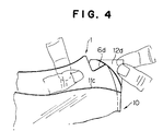
- the dust cover 10 is formed at respective corner portions with hooking straps 12a, 12b, 12c and 12d for engagement with the respective cutouts 6a, 6b, 6c and 6d in the file sheet 1.
- the straps 12a, 12b, 12c and 12d are engaged with respective ones of the cutouts 6a, 6b, 6c and 6d as shown in Figures 3 and 4 so that the dust cover 10 is firmly held on the file sheet 1.
- the edge portions having the ridges 5a and 5b are exposed from the dust cover 10 as shown in Figure 2.
- the file sheet 1 with the dust cover 10 shown in Figure 1 can be held in position in the binder 20 by having the ridge 5a or 5b engaged with the groove 20d of the binding member 20a. In this position, the ridge 5a or 5b is engaged with the inner face of one of the pawl 20e forming the slit opening 20c.
- Figures 7 and 8 show the file sheets 1 with the dust cover 10 thereon held in the binder 20.
- Cover sheets may be engaged with the outermost ones of the binding members 20a of the binder 20 and the file sheets 1 may be held by intermediate ones of the binding members 20a.
- the cover sheets may not be necessary.
- the number of the binding members 20a can be increased as desried. For example, two binders 20 having four binding members 20a may be connected together by means of an adhesive tape. Alternatively, the number of the binding members 20a may be determined as desired when they are welded together by the plastic tape 20b.
- the binder 30 includes a plurality of binding members 31 which are made of extrusions of a solid plastic material.
- the binding member 31 includes a pair of opposed binding pieces 31a of annular cross-sectional shape and a base portion 31b continuous with the binding sections 31a.
- the binding sections 31a are arranged to define a groove 31d having a slit opening 31c.
- the groove 31d is of a cross-sectional configuration enlarged toward transverse inward direction from the slit opening 31c.
- the slit opening 31c is defined by edges of the opposed binding sections 31a.
- In the base portion 31b there is formed a groove 31e of a trapezoidal cross-sectional configuration.
- the binding members 31 are connected together by means of connecting members 32.
- the connecting member 32 includes a plurality of bodies 32a and projections 32b extending from respective ones of the bodies 32a.
- the bodies 32a and the projections 32b are made integrally from a plastic material.
- the projection 32b has a cross-sectional configuration corresponding to the cross-sectional configuration of the groove 31e of the binding member 31.
- the bodies 32a are connected together by means of flexible connecting bands 32c.
- the binding members 31 are connected together by the connecting member 32 by having the projections 32b of the connecting member 32 engaged with the grooves 31d of the binding members 31.
- the binding members 31 are connected together at the opposite end portions by two connecting members 32.
- FIGs 12 through 14 show a further embodiment of the binder.
- the binder 40 is constituted by a plurality of binding members 41a which are connected together.
- Each of the binding members 41a includes a wall 42 and a binding section 43 provided at a sidewardly offset position with respect to the wall 42.
- the wall 42 and the binding section 43 are connected together by a base 44 as shown in Figure 13.
- the base 44 is formed with a groove 44a which provides a flexibility to the base 44.
- the binding section 43 has a pawl 43a which is directed opposite to the wall 42.
- the binding members 41 are connected together by welding the bottom portion of the binding section 43 to the wall 42 of the adjacent binding member 41 with the pawl 43a of the binding section 43 directed to the wall 42 of the adjacent binding member 41.
- a file sheet 1 having a ridge 5a at one edge portion is inserted between the wall 42 of one binding member 41 and the binding section 43 of the adjacent binding member 41.
- the ridge 5a of the file sheet 1 is then gripped in position by the pawl 43a of the binding section 43.
- the dust cover 50 is similar in structure to the dust cover shown in Figure 1 except that the opposite sheets 50a and 50b of the dust cover 50 are not connected together at the edge portion 51a.
- the top sheet 50a is bent at the edge portion 51a to form a folded portion 52.
- the file sheet 1 is inserted into the dust cover 50 with the top sheet 50a peeled from the bottom sheet 50b at the edge portion 51a. Then, the top sheet 50a is placed on the top surface of the file sheet 1 and the folded portion 52 is engaged with the adjacent edge of the bottom sheet 50b.
- the device 60 includes a frame 62 for hanging binding members 61 holding file sheets 1.
- the binding members 61 are similar to the binding members 20a in the embodiment shown in Figures 1 and 2 and have slit openings 61a where the file sheets 1 are engaged.
- the binding member 61 is formed at a portion adjacent to each end portion with a cutout 61b.
- the frame 62 has hanging members 62a which are adapted to be engaged with the respective ones of the cutouts 61b in the binding members 61.
- the binding members 61 carrying the file sheets 1 are hung on the frame 62 as shown in Figure 16.
- the present invention provides a filing device in which file sheets can readily be filed or removed.
- the binding member of the present invention allows to determine the capacity of the file as desired by adding or removing the binding member.
- the present invention provides a simple and compact file device.
Landscapes
- Physics & Mathematics (AREA)
- General Physics & Mathematics (AREA)
- Engineering & Computer Science (AREA)
- Theoretical Computer Science (AREA)
- Sheet Holders (AREA)
Applications Claiming Priority (2)
| Application Number | Priority Date | Filing Date | Title |
|---|---|---|---|
| JP56972/91 | 1991-03-20 | ||
| JP3056972A JPH0741751B2 (ja) | 1991-03-20 | 1991-03-20 | ファイルシート保存装置 |
Publications (2)
| Publication Number | Publication Date |
|---|---|
| EP0510799A1 true EP0510799A1 (fr) | 1992-10-28 |
| EP0510799B1 EP0510799B1 (fr) | 1995-07-19 |
Family
ID=13042439
Family Applications (1)
| Application Number | Title | Priority Date | Filing Date |
|---|---|---|---|
| EP92302145A Expired - Lifetime EP0510799B1 (fr) | 1991-03-20 | 1992-03-12 | Dispositif d'archivage pour feuilles avec poche de protection |
Country Status (4)
| Country | Link |
|---|---|
| US (1) | US5238270A (fr) |
| EP (1) | EP0510799B1 (fr) |
| JP (1) | JPH0741751B2 (fr) |
| DE (1) | DE69203520T2 (fr) |
Families Citing this family (2)
| Publication number | Priority date | Publication date | Assignee | Title |
|---|---|---|---|---|
| US9290035B2 (en) | 2005-02-18 | 2016-03-22 | ACCO Brands Corporation | Refillable notebook with release mechanism |
| CA2734076C (fr) | 2005-02-18 | 2013-05-07 | Meadwestvaco Corporation | Carnet rechargeable |
Citations (5)
| Publication number | Priority date | Publication date | Assignee | Title |
|---|---|---|---|---|
| CH564239A5 (en) * | 1973-03-08 | 1975-07-15 | Ursonia Anstalt | Rack for holding carpet samples - can be built up to required size and opens like book for clear viewing and easy handling |
| FR2509669A1 (fr) * | 1981-07-15 | 1983-01-21 | Jowa Sa | Reliure pour documents et autres objets presentes en feuilles |
| EP0342948A2 (fr) * | 1988-05-19 | 1989-11-23 | Slidex Corporation | Couverture de protection pour feuille de classement |
| CH672910A5 (fr) * | 1987-06-19 | 1990-01-15 | Walter Ag Alfred | |
| DE3830707A1 (de) * | 1988-09-09 | 1990-03-22 | Lachenmaier & Co Kg G | Buch mit steifen blaettern |
Family Cites Families (5)
| Publication number | Priority date | Publication date | Assignee | Title |
|---|---|---|---|---|
| US4128262A (en) * | 1977-09-06 | 1978-12-05 | Corday Gerard M Du | Magazine cover |
| US4351124A (en) * | 1981-01-14 | 1982-09-28 | General Electric Company | Film mount with protected face sheet |
| US5040671A (en) * | 1990-01-22 | 1991-08-20 | Hager Alan C | Protective case for collectible flat items |
| US5046616A (en) * | 1990-07-05 | 1991-09-10 | Makowski Jeffrey S | Card display plaque |
| US5119574A (en) * | 1990-12-14 | 1992-06-09 | U.S. Sample Company | Collector's album having transparent display pages with sheet retainers |
-
1991
- 1991-03-20 JP JP3056972A patent/JPH0741751B2/ja not_active Expired - Lifetime
-
1992
- 1992-03-12 EP EP92302145A patent/EP0510799B1/fr not_active Expired - Lifetime
- 1992-03-12 DE DE69203520T patent/DE69203520T2/de not_active Expired - Fee Related
- 1992-03-16 US US07/851,596 patent/US5238270A/en not_active Expired - Fee Related
Patent Citations (5)
| Publication number | Priority date | Publication date | Assignee | Title |
|---|---|---|---|---|
| CH564239A5 (en) * | 1973-03-08 | 1975-07-15 | Ursonia Anstalt | Rack for holding carpet samples - can be built up to required size and opens like book for clear viewing and easy handling |
| FR2509669A1 (fr) * | 1981-07-15 | 1983-01-21 | Jowa Sa | Reliure pour documents et autres objets presentes en feuilles |
| CH672910A5 (fr) * | 1987-06-19 | 1990-01-15 | Walter Ag Alfred | |
| EP0342948A2 (fr) * | 1988-05-19 | 1989-11-23 | Slidex Corporation | Couverture de protection pour feuille de classement |
| DE3830707A1 (de) * | 1988-09-09 | 1990-03-22 | Lachenmaier & Co Kg G | Buch mit steifen blaettern |
Also Published As
| Publication number | Publication date |
|---|---|
| US5238270A (en) | 1993-08-24 |
| EP0510799B1 (fr) | 1995-07-19 |
| DE69203520T2 (de) | 1995-12-21 |
| JPH0741751B2 (ja) | 1995-05-10 |
| JPH05193294A (ja) | 1993-08-03 |
| DE69203520D1 (de) | 1995-08-24 |
Similar Documents
| Publication | Publication Date | Title |
|---|---|---|
| US4521035A (en) | Paper sheet holders | |
| EP0420387B1 (fr) | Reliure pour documents en feuilles | |
| US5464091A (en) | Protective covers | |
| CA2124060C (fr) | Reliure de calepins | |
| EP0022652A1 (fr) | Récipient pour disques d'enregistrement | |
| US4730972A (en) | Book binding method, paper sheets binder and adjustable spine | |
| US5904245A (en) | Storage arrangement for recording media using detachable mounting components | |
| US4932804A (en) | Loose leaf retainer for file folders | |
| US4253567A (en) | Cassette container | |
| EP0479556A1 (fr) | Moyen de stockage et de transport | |
| EP0606215B1 (fr) | Album de photographies et procede de fabrication dudit album | |
| US5303825A (en) | Storage assemblage for index print sheets and cassettes | |
| EP0510799B1 (fr) | Dispositif d'archivage pour feuilles avec poche de protection | |
| US5301803A (en) | Package for index print sheet and cassette | |
| US20050103659A1 (en) | Means of attaching rigid pages to a book-like cover | |
| EP0186359A2 (fr) | Récipient pour logiciel | |
| RU2000102644A (ru) | Устройство для хранения дисковых носителей звука и/или информации | |
| US5538287A (en) | Binder for file sheets | |
| US5909897A (en) | Photo album for storing pictures and APS film cartridges | |
| GB2091690A (en) | Container for tape cassettes | |
| JPS60192696A (ja) | フアイル | |
| JP3024422U (ja) | ミニディスク保管用ケース | |
| JP3055818U (ja) | バインダー着脱可能な書類ホルダー | |
| JPS6017346Y2 (ja) | フアイル | |
| GB2323815A (en) | A binder having intermediate page holders |
Legal Events
| Date | Code | Title | Description |
|---|---|---|---|
| PUAI | Public reference made under article 153(3) epc to a published international application that has entered the european phase |
Free format text: ORIGINAL CODE: 0009012 |
|
| AK | Designated contracting states |
Kind code of ref document: A1 Designated state(s): DE GB |
|
| 17P | Request for examination filed |
Effective date: 19930423 |
|
| 17Q | First examination report despatched |
Effective date: 19941006 |
|
| GRAA | (expected) grant |
Free format text: ORIGINAL CODE: 0009210 |
|
| AK | Designated contracting states |
Kind code of ref document: B1 Designated state(s): DE GB |
|
| REF | Corresponds to: |
Ref document number: 69203520 Country of ref document: DE Date of ref document: 19950824 |
|
| PLBE | No opposition filed within time limit |
Free format text: ORIGINAL CODE: 0009261 |
|
| STAA | Information on the status of an ep patent application or granted ep patent |
Free format text: STATUS: NO OPPOSITION FILED WITHIN TIME LIMIT |
|
| 26N | No opposition filed | ||
| PGFP | Annual fee paid to national office [announced via postgrant information from national office to epo] |
Ref country code: GB Payment date: 19990311 Year of fee payment: 8 |
|
| PGFP | Annual fee paid to national office [announced via postgrant information from national office to epo] |
Ref country code: DE Payment date: 19990330 Year of fee payment: 8 |
|
| PG25 | Lapsed in a contracting state [announced via postgrant information from national office to epo] |
Ref country code: GB Free format text: LAPSE BECAUSE OF NON-PAYMENT OF DUE FEES Effective date: 20000312 |
|
| GBPC | Gb: european patent ceased through non-payment of renewal fee |
Effective date: 20000312 |
|
| PG25 | Lapsed in a contracting state [announced via postgrant information from national office to epo] |
Ref country code: DE Free format text: LAPSE BECAUSE OF NON-PAYMENT OF DUE FEES Effective date: 20010103 |