EP0511279B1 - Interlocking device for joining together ceiling or wall elements - Google Patents
Interlocking device for joining together ceiling or wall elements Download PDFInfo
- Publication number
- EP0511279B1 EP0511279B1 EP91903046A EP91903046A EP0511279B1 EP 0511279 B1 EP0511279 B1 EP 0511279B1 EP 91903046 A EP91903046 A EP 91903046A EP 91903046 A EP91903046 A EP 91903046A EP 0511279 B1 EP0511279 B1 EP 0511279B1
- Authority
- EP
- European Patent Office
- Prior art keywords
- elements
- wall
- interlocking device
- ceiling
- flange
- Prior art date
- Legal status (The legal status is an assumption and is not a legal conclusion. Google has not performed a legal analysis and makes no representation as to the accuracy of the status listed.)
- Expired - Lifetime
Links
- 239000011324 bead Substances 0.000 claims abstract description 10
- 239000000463 material Substances 0.000 claims abstract description 7
- 229910052751 metal Inorganic materials 0.000 claims abstract description 4
- 239000002184 metal Substances 0.000 claims abstract description 4
- 239000004033 plastic Substances 0.000 claims abstract description 4
- 229920003023 plastic Polymers 0.000 claims abstract description 4
- 238000009435 building construction Methods 0.000 claims description 5
- 229910000831 Steel Inorganic materials 0.000 claims description 3
- 239000010959 steel Substances 0.000 claims description 3
- 229910052782 aluminium Inorganic materials 0.000 claims description 2
- XAGFODPZIPBFFR-UHFFFAOYSA-N aluminium Chemical compound [Al] XAGFODPZIPBFFR-UHFFFAOYSA-N 0.000 claims description 2
- 239000012774 insulation material Substances 0.000 claims description 2
- 239000002991 molded plastic Substances 0.000 claims description 2
- 238000007789 sealing Methods 0.000 claims description 2
- 230000000694 effects Effects 0.000 abstract description 4
- 230000000712 assembly Effects 0.000 description 2
- 238000000429 assembly Methods 0.000 description 2
- 230000015572 biosynthetic process Effects 0.000 description 2
- 238000004519 manufacturing process Methods 0.000 description 2
- 238000009439 industrial construction Methods 0.000 description 1
- 238000003780 insertion Methods 0.000 description 1
- 230000037431 insertion Effects 0.000 description 1
Images


Classifications
-
- E—FIXED CONSTRUCTIONS
- E04—BUILDING
- E04B—GENERAL BUILDING CONSTRUCTIONS; WALLS, e.g. PARTITIONS; ROOFS; FLOORS; CEILINGS; INSULATION OR OTHER PROTECTION OF BUILDINGS
- E04B9/00—Ceilings; Construction of ceilings, e.g. false ceilings; Ceiling construction with regard to insulation
- E04B9/04—Ceilings; Construction of ceilings, e.g. false ceilings; Ceiling construction with regard to insulation comprising slabs, panels, sheets or the like
- E04B9/0478—Ceilings; Construction of ceilings, e.g. false ceilings; Ceiling construction with regard to insulation comprising slabs, panels, sheets or the like of the tray type
-
- E—FIXED CONSTRUCTIONS
- E04—BUILDING
- E04D—ROOF COVERINGS; SKY-LIGHTS; GUTTERS; ROOF-WORKING TOOLS
- E04D3/00—Roof covering by making use of flat or curved slabs or stiff sheets
- E04D3/36—Connecting; Fastening
- E04D3/365—Connecting; Fastening by simple overlapping of the marginal portions with use of separate connecting elements, e.g. hooks or bolts for corrugated sheets
-
- E—FIXED CONSTRUCTIONS
- E04—BUILDING
- E04F—FINISHING WORK ON BUILDINGS, e.g. STAIRS, FLOORS
- E04F13/00—Coverings or linings, e.g. for walls or ceilings
- E04F13/07—Coverings or linings, e.g. for walls or ceilings composed of covering or lining elements; Sub-structures therefor; Fastening means therefor
- E04F13/08—Coverings or linings, e.g. for walls or ceilings composed of covering or lining elements; Sub-structures therefor; Fastening means therefor composed of a plurality of similar covering or lining elements
- E04F13/12—Coverings or linings, e.g. for walls or ceilings composed of covering or lining elements; Sub-structures therefor; Fastening means therefor composed of a plurality of similar covering or lining elements of metal or with an outer layer of metal or enameled metal
Definitions
- the invention relates to an interlocking device for joining together pre-manufactured ceiling or wall elements, particularly elements produced from metal or plastic materials, the single element being bent and/or moulded in plank or plate-like open box form, in which an insulation material may be located, and the longitudinal walls of an elements being profiled in order to join the elements together to form a substantially whole, plane surface composed of the outward facing plane surfaces of the single elements.
- US patent No. 1,738,469, US 2,478,060 and Danish patent No. 151.977 disclose e.g. so-called furring strips or rails for wall- or ceiling coverings, wherein the furring strips or rails after having been secured to a ceiling support beam are used for rigidly mounting a pre-manufactured plank- or plate ceiling, the elements forming together a ceiling cover and the single strip serving also as an interlocking device between adjacent single elements.
- US patent No. 4,520,607 further discloses a resilient mounting assembly, a so-called clip, for mounting of a ceiling cover of single elements or for mounting of a wall also of single elements which are inserted into the clip, and said clip being secured to an assembly beam which constitutes part of said building construction.
- Danish patent application No. 3133/84 discloses a plate element having interlocking devices disposed on opposite sides, each element being provided with a bent interlocking device which is incorporated into the element wall and which may be placed in a corresponding interlocking device on the opposite wall of an adjacent plate element so as to allow the elements, by means of the interlocking devices, to be joined together in the direction of the entire element surface and independent of a mounting assembly in the building construction proper.
- the two interlocking devices require relatively complicated bends of the longitudinal walls on each element and thus demand a complicated manufacturing process of the single elements just as necessary precautions must be taken in storing, transporting and mounting of each element in order to safeguard the exposed bends.
- the object is obtained by joining together separate elements by means of an interlocking device according to the characterising part of claim 1 so as to form a substantially plane surface of single elements.
- the interlocking device may be produced, in a manner known per se, from a fire proof material, e.g. steel, especially in case of element surfaces which are used in industrial constructions or for ship fittings.
- Fig. 1 shows a perspective exploded view of two pre-manufactured ceiling- or wall elements complete with an interlocking device for joining together the elements.
- Fig. 2 shows a vertical cross-sectional view of an interlocking device ("clip-profile") according to the invention.
- Fig. 3 shows a vertical cross-sectional view of a ceiling or wall element which is designed to be joined together with a corresponding element by means of an interlocking device.
- Fig. 4 also shows a vertical cross-sectional view of the joining together of two ceiling or wall elements by means of the interlocking device shown in Fig. 2.
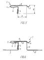
- Fig. 5 shows a vertical sectional view through an interlocking device corresponding to the one shown in Fig. 2 but designed to form a notch between two adjacent elements.
- Fig. 6 shows a sectional view through two adjacent ceiling or wall elements which are joined together by the interlocking device shown in Fig. 5 and with a notch between the elements.
- a clip-profile which in joining together two adjacent ceiling or wall elements 2, 12 snaps over the longitudinal wall profile 5 on the right side of the element 2, and subsequently the wall profile 11 on the left side of the element 12 is inserted into the interlocking device in the direction towards the element 2.
- the T-shaped interlocking device (Fig. 2) consists of a profile element 1 having a bent or doubled-back lower end made from steel, extruded aluminum or moulded plastics with a vertical stem 4 which at the top continues in a smaller, left facing surface 6, a 180° bend 7 and an upper, wider right facing surface 8 which terminates in a longitudinal bead 9 which projects downwards towards the stem 4.
- a resilient effect between the surfaces 6 and 8 is obtained.
- the interlocking device is designed to be attached on the right wall 5 of the element 2 shown in Fig. 3 along its entire length by inserting the small inwardly projecting flange 3, which is provided with a longitudinal bead, between the surfaces 6 and 8 of the interlocking device so as to lock the surfaces around the flange 3 and to abut the stem 4 against the inside of the wall 5, see Fig. 4.
- the left wall 11 having an outwardly projecting angularly bended flange 10 on the adjacent element is inserted into the interlocking device 1 between the downwards facing surface 8 of said interlocking device and the upperside of the inwardly projecting flange of the element 2, the surface 8 thereby being pushed upwards due to the bead 9 thus making the insertion possible.
- Fig. 5 shows a variation of the interlocking device, the surface 8 here being wider and thus the bead 9 being further to the right.
- H indicates the height of the interlocking device which corresponds to the thickness of the elements to be joined.
- the greater width of the surface 8 corresponds to a greater width of the surface of the flange 10 in order for two adjacent elements 2 and 12 to be joined together under the formation of a notch with a given width A between the elements thereby creating a play in the element surface as a whole to fulfill esthetic requirements.
- the interlocking device 1 is placed on the wall 5 with the flange 3 in the same manner as described in connection with Fig. 3 and 4. Subsequently, the flange 10 of the element 12 is inserted into the interlocking device between the surface 8 of said device and the upper side of the flange 3 of the element 2 until the bead 9 slides down on the inside of the wall 11 of the element 12, and due to the spring effect between the surfaces 6 and 8 of the interlocking device tightly joins the element 12 to the element 2 under the formation of the notch between the two elements.
- the length of the single interlocking device may be adapted to the length of the single ceiling- or wall element in such a manner as to allow space at each end of an element for fastening of mounting assemblies for mounting of the element in the building construction and/or for the end sealing of the element.
- the length of the interlocking device may constitute a fraction of the length of the single ceiling or wall element so that in locking together said elements a certain number of interlocking devices must be used for each length to be locked together in order to facilitate the locking together of long elements which may be exposed to relatively strong bending- and torsion forces during assembly, and to allow space for fastening of mounting assemblies to the building construction along the locking length.
Landscapes
- Engineering & Computer Science (AREA)
- Architecture (AREA)
- Civil Engineering (AREA)
- Structural Engineering (AREA)
- Physics & Mathematics (AREA)
- Electromagnetism (AREA)
- Mechanical Engineering (AREA)
- Joining Of Building Structures In Genera (AREA)
- Roof Covering Using Slabs Or Stiff Sheets (AREA)
- Building Environments (AREA)
Applications Claiming Priority (2)
| Application Number | Priority Date | Filing Date | Title |
|---|---|---|---|
| DK012090A DK164823C (da) | 1990-01-15 | 1990-01-15 | Samleorgan til indbyrdes sammenlaasning af lofts- eller vaegelementer |
| DK120/90 | 1990-01-15 |
Publications (2)
| Publication Number | Publication Date |
|---|---|
| EP0511279A1 EP0511279A1 (en) | 1992-11-04 |
| EP0511279B1 true EP0511279B1 (en) | 1993-12-01 |
Family
ID=8089976
Family Applications (1)
| Application Number | Title | Priority Date | Filing Date |
|---|---|---|---|
| EP91903046A Expired - Lifetime EP0511279B1 (en) | 1990-01-15 | 1991-01-09 | Interlocking device for joining together ceiling or wall elements |
Country Status (7)
| Country | Link |
|---|---|
| EP (1) | EP0511279B1 (da) |
| DE (1) | DE69100718T2 (da) |
| DK (1) | DK164823C (da) |
| ES (1) | ES2046890T3 (da) |
| FI (1) | FI97077C (da) |
| NO (1) | NO176217C (da) |
| WO (1) | WO1991010787A1 (da) |
Families Citing this family (5)
| Publication number | Priority date | Publication date | Assignee | Title |
|---|---|---|---|---|
| DK282290D0 (da) * | 1990-11-28 | 1990-11-28 | Dampa As | Laaseorgan til fastholdelse af lofts- eller vaegelementer |
| FI93250C (fi) * | 1992-10-15 | 1995-03-10 | Shippax Ltd Oy | Liitoselementti ja sen käyttö |
| FR2755161B1 (fr) * | 1996-10-30 | 1998-11-27 | Pab Services | Dispositif de fixation de couvre-joint |
| GB2377270A (en) * | 2001-02-22 | 2003-01-08 | Be Modern Ltd | A multi-panelled fire surround |
| WO2007048182A1 (en) * | 2005-10-25 | 2007-05-03 | Fielders Australia Pty Ltd | Steel decking with intermediate infill panels |
Family Cites Families (5)
| Publication number | Priority date | Publication date | Assignee | Title |
|---|---|---|---|---|
| US1738469A (en) * | 1929-01-24 | 1929-12-03 | Burgess Lab Inc C F | Furring strip |
| US2478060A (en) * | 1945-02-27 | 1949-08-02 | S H Pomeroy Company Inc | Furring strip |
| DE2807942C2 (de) * | 1978-02-24 | 1986-12-11 | Hunter Douglas Industries B.V., Rotterdam | Auskleidung für Decken oder Wände, insbesondere für Fassaden |
| GB2080356B (en) * | 1980-06-17 | 1984-02-01 | Hunter Douglas Ind Bv | Panelling and carriers therefor |
| GB2118988B (en) * | 1982-03-17 | 1985-09-04 | Hunter Douglas Ind Bv | Panelling and carriers therefor |
-
1990
- 1990-01-15 DK DK012090A patent/DK164823C/da not_active IP Right Cessation
-
1991
- 1991-01-09 WO PCT/DK1991/000005 patent/WO1991010787A1/en not_active Ceased
- 1991-01-09 EP EP91903046A patent/EP0511279B1/en not_active Expired - Lifetime
- 1991-01-09 DE DE91903046T patent/DE69100718T2/de not_active Expired - Fee Related
- 1991-01-09 ES ES199191903046T patent/ES2046890T3/es not_active Expired - Lifetime
-
1992
- 1992-07-10 NO NO922734A patent/NO176217C/no unknown
- 1992-07-14 FI FI923231A patent/FI97077C/fi active
Also Published As
| Publication number | Publication date |
|---|---|
| FI923231L (fi) | 1992-07-14 |
| FI97077C (fi) | 1996-10-10 |
| DK164823C (da) | 1993-01-11 |
| NO176217C (no) | 1995-02-22 |
| WO1991010787A1 (en) | 1991-07-25 |
| ES2046890T3 (es) | 1994-02-01 |
| NO922734D0 (no) | 1992-07-10 |
| EP0511279A1 (en) | 1992-11-04 |
| FI97077B (fi) | 1996-06-28 |
| DE69100718T2 (de) | 1994-05-05 |
| DE69100718D1 (de) | 1994-01-13 |
| DK12090A (da) | 1991-07-16 |
| FI923231A0 (fi) | 1992-07-14 |
| NO922734L (no) | 1992-09-07 |
| DK164823B (da) | 1992-08-24 |
| NO176217B (no) | 1994-11-14 |
| DK12090D0 (da) | 1990-01-15 |
Similar Documents
| Publication | Publication Date | Title |
|---|---|---|
| US3331171A (en) | Joint covers | |
| US4020611A (en) | Wall assembly | |
| US4272576A (en) | Wall covering | |
| US4913576A (en) | Molding bracket for covering the end of a panel subject to thermal expansion | |
| EP0339216B1 (en) | Translucent self-supporting enclosure for building structures | |
| US3381434A (en) | Glass division bar | |
| EP0511279B1 (en) | Interlocking device for joining together ceiling or wall elements | |
| US5433054A (en) | Frame structures, especially for inspection and access openings in walls, roofs and ceilings | |
| WO2008131755A1 (en) | Window structure with a fitting for assembling the corners of the window sash | |
| GB2125844A (en) | Connecting building panels | |
| KR20220082714A (ko) | 벽면 모서리용 진공단열재 설치 브라켓 | |
| JP2656266B2 (ja) | 壁 体 | |
| KR100714547B1 (ko) | 프레임 구조물 | |
| KR102386523B1 (ko) | 미들조인트부재로 연결된 확장형 단위 메탈판넬 | |
| JPH0720274Y2 (ja) | 鎧型横張内外装材用出隅部材 | |
| JPH0446440Y2 (da) | ||
| JP2862201B2 (ja) | エキスパンションジョイントのカバー材連結機構 | |
| JPS6320739Y2 (da) | ||
| JPH0720271Y2 (ja) | 鎧型横張内外装材用出隅部材 | |
| JPH0721714Y2 (ja) | 鎧型横張内外装材用出隅部材 | |
| JPH0720272Y2 (ja) | 鎧型横張内外装材用出隅部材 | |
| JP4313737B2 (ja) | 外壁材の取付構造及び外壁材の取付方法 | |
| JPH0323932Y2 (da) | ||
| JPS6328764Y2 (da) | ||
| JPH0718837Y2 (ja) | 鎧型横張内外装材用入隅部材 |
Legal Events
| Date | Code | Title | Description |
|---|---|---|---|
| PUAI | Public reference made under article 153(3) epc to a published international application that has entered the european phase |
Free format text: ORIGINAL CODE: 0009012 |
|
| 17P | Request for examination filed |
Effective date: 19920704 |
|
| AK | Designated contracting states |
Kind code of ref document: A1 Designated state(s): BE DE ES FR GB GR IT NL SE |
|
| 17Q | First examination report despatched |
Effective date: 19930219 |
|
| GRAA | (expected) grant |
Free format text: ORIGINAL CODE: 0009210 |
|
| AK | Designated contracting states |
Kind code of ref document: B1 Designated state(s): BE DE ES FR GB GR IT NL SE |
|
| PG25 | Lapsed in a contracting state [announced via postgrant information from national office to epo] |
Ref country code: NL Effective date: 19931201 Ref country code: GR Free format text: LAPSE BECAUSE OF FAILURE TO SUBMIT A TRANSLATION OF THE DESCRIPTION OR TO PAY THE FEE WITHIN THE PRESCRIBED TIME-LIMIT Effective date: 19931201 Ref country code: BE Effective date: 19931201 |
|
| ET | Fr: translation filed | ||
| REF | Corresponds to: |
Ref document number: 69100718 Country of ref document: DE Date of ref document: 19940113 |
|
| REG | Reference to a national code |
Ref country code: ES Ref legal event code: FG2A Ref document number: 2046890 Country of ref document: ES Kind code of ref document: T3 |
|
| ITF | It: translation for a ep patent filed | ||
| NLV1 | Nl: lapsed or annulled due to failure to fulfill the requirements of art. 29p and 29m of the patents act | ||
| PLBE | No opposition filed within time limit |
Free format text: ORIGINAL CODE: 0009261 |
|
| STAA | Information on the status of an ep patent application or granted ep patent |
Free format text: STATUS: NO OPPOSITION FILED WITHIN TIME LIMIT |
|
| 26N | No opposition filed | ||
| PG25 | Lapsed in a contracting state [announced via postgrant information from national office to epo] |
Ref country code: GB Effective date: 19950109 |
|
| EAL | Se: european patent in force in sweden |
Ref document number: 91903046.0 |
|
| GBPC | Gb: european patent ceased through non-payment of renewal fee |
Effective date: 19950109 |
|
| PGFP | Annual fee paid to national office [announced via postgrant information from national office to epo] |
Ref country code: FR Payment date: 19971127 Year of fee payment: 8 |
|
| PGFP | Annual fee paid to national office [announced via postgrant information from national office to epo] |
Ref country code: SE Payment date: 19971204 Year of fee payment: 8 |
|
| PGFP | Annual fee paid to national office [announced via postgrant information from national office to epo] |
Ref country code: ES Payment date: 19980114 Year of fee payment: 8 |
|
| PGFP | Annual fee paid to national office [announced via postgrant information from national office to epo] |
Ref country code: DE Payment date: 19980122 Year of fee payment: 8 |
|
| PG25 | Lapsed in a contracting state [announced via postgrant information from national office to epo] |
Ref country code: SE Free format text: LAPSE BECAUSE OF NON-PAYMENT OF DUE FEES Effective date: 19990110 |
|
| PG25 | Lapsed in a contracting state [announced via postgrant information from national office to epo] |
Ref country code: ES Free format text: LAPSE BECAUSE OF EXPIRATION OF PROTECTION Effective date: 19990111 |
|
| PG25 | Lapsed in a contracting state [announced via postgrant information from national office to epo] |
Ref country code: FR Free format text: LAPSE BECAUSE OF NON-PAYMENT OF DUE FEES Effective date: 19990930 |
|
| PG25 | Lapsed in a contracting state [announced via postgrant information from national office to epo] |
Ref country code: DE Free format text: LAPSE BECAUSE OF NON-PAYMENT OF DUE FEES Effective date: 19991103 |
|
| REG | Reference to a national code |
Ref country code: FR Ref legal event code: ST |
|
| REG | Reference to a national code |
Ref country code: ES Ref legal event code: FD2A Effective date: 20010601 |
|
| PG25 | Lapsed in a contracting state [announced via postgrant information from national office to epo] |
Ref country code: IT Free format text: LAPSE BECAUSE OF NON-PAYMENT OF DUE FEES;WARNING: LAPSES OF ITALIAN PATENTS WITH EFFECTIVE DATE BEFORE 2007 MAY HAVE OCCURRED AT ANY TIME BEFORE 2007. THE CORRECT EFFECTIVE DATE MAY BE DIFFERENT FROM THE ONE RECORDED. Effective date: 20050109 |