EP0511595A1 - Débitmètre - Google Patents
Débitmètre Download PDFInfo
- Publication number
- EP0511595A1 EP0511595A1 EP92106986A EP92106986A EP0511595A1 EP 0511595 A1 EP0511595 A1 EP 0511595A1 EP 92106986 A EP92106986 A EP 92106986A EP 92106986 A EP92106986 A EP 92106986A EP 0511595 A1 EP0511595 A1 EP 0511595A1
- Authority
- EP
- European Patent Office
- Prior art keywords
- core
- measuring tube
- molded part
- powder
- molded
- Prior art date
- Legal status (The legal status is an assumption and is not a legal conclusion. Google has not performed a legal analysis and makes no representation as to the accuracy of the status listed.)
- Withdrawn
Links
- 230000005291 magnetic effect Effects 0.000 claims abstract description 29
- 239000000843 powder Substances 0.000 claims abstract description 20
- 239000007788 liquid Substances 0.000 claims abstract description 9
- 230000005284 excitation Effects 0.000 claims abstract description 7
- 239000002245 particle Substances 0.000 claims abstract description 6
- 230000005294 ferromagnetic effect Effects 0.000 claims abstract description 5
- 239000011230 binding agent Substances 0.000 claims description 6
- 238000009413 insulation Methods 0.000 claims description 6
- 239000004033 plastic Substances 0.000 claims description 4
- 239000002902 ferrimagnetic material Substances 0.000 claims description 2
- 238000001746 injection moulding Methods 0.000 claims description 2
- 150000001247 metal acetylides Chemical class 0.000 claims description 2
- 150000004767 nitrides Chemical class 0.000 claims description 2
- 229920001169 thermoplastic Polymers 0.000 claims description 2
- 229920001187 thermosetting polymer Polymers 0.000 claims description 2
- 239000004416 thermosoftening plastic Substances 0.000 claims description 2
- 230000007717 exclusion Effects 0.000 claims 1
- 230000004907 flux Effects 0.000 description 5
- 230000035699 permeability Effects 0.000 description 4
- 239000011810 insulating material Substances 0.000 description 3
- 239000000463 material Substances 0.000 description 3
- 230000006978 adaptation Effects 0.000 description 2
- 210000000988 bone and bone Anatomy 0.000 description 2
- 238000010276 construction Methods 0.000 description 2
- 238000005516 engineering process Methods 0.000 description 2
- 238000007731 hot pressing Methods 0.000 description 2
- 238000004519 manufacturing process Methods 0.000 description 2
- 238000005457 optimization Methods 0.000 description 2
- 238000005245 sintering Methods 0.000 description 2
- 230000015572 biosynthetic process Effects 0.000 description 1
- 239000002800 charge carrier Substances 0.000 description 1
- 239000002131 composite material Substances 0.000 description 1
- 230000006835 compression Effects 0.000 description 1
- 238000007906 compression Methods 0.000 description 1
- 238000010292 electrical insulation Methods 0.000 description 1
- 238000011156 evaluation Methods 0.000 description 1
- 239000003302 ferromagnetic material Substances 0.000 description 1
- 230000006698 induction Effects 0.000 description 1
- 238000005304 joining Methods 0.000 description 1
- 239000002184 metal Substances 0.000 description 1
- 229910052751 metal Inorganic materials 0.000 description 1
- 239000000203 mixture Substances 0.000 description 1
- 238000000465 moulding Methods 0.000 description 1
- 239000011347 resin Substances 0.000 description 1
- 229920005989 resin Polymers 0.000 description 1
- 239000013589 supplement Substances 0.000 description 1
- 238000003466 welding Methods 0.000 description 1
- 238000004804 winding Methods 0.000 description 1
Images


Classifications
-
- G—PHYSICS
- G01—MEASURING; TESTING
- G01F—MEASURING VOLUME, VOLUME FLOW, MASS FLOW OR LIQUID LEVEL; METERING BY VOLUME
- G01F1/00—Measuring the volume flow or mass flow of fluid or fluent solid material wherein the fluid passes through a meter in a continuous flow
- G01F1/56—Measuring the volume flow or mass flow of fluid or fluent solid material wherein the fluid passes through a meter in a continuous flow by using electric or magnetic effects
- G01F1/58—Measuring the volume flow or mass flow of fluid or fluent solid material wherein the fluid passes through a meter in a continuous flow by using electric or magnetic effects by electromagnetic flowmeters
- G01F1/586—Measuring the volume flow or mass flow of fluid or fluent solid material wherein the fluid passes through a meter in a continuous flow by using electric or magnetic effects by electromagnetic flowmeters constructions of coils, magnetic circuits, accessories therefor
Definitions
- the invention relates to a magnetic-inductive flow meter for liquids with a measuring tube carrying the liquid and an electromagnet for generating a low-frequency magnetic field in the measuring tube, the electromagnet having at least one excitation coil and a core surrounding the measuring tube.
- Flowmeters of this type use the induction principle, according to which a voltage is induced in the case of moving charge carriers by applying a magnetic field perpendicular to the direction of movement.
- the voltage is perpendicular to the direction of movement and perpendicular to the magnetic field and is tapped via appropriately arranged electrodes.
- This measuring voltage is proportional to the average speed, so that the volume or mass flow of a conductive liquid in the measuring tube can be determined with the aid of this voltage.
- Time-varying magnetic fields are preferably used. These are then either switched or change periodically with frequencies below 1 kHz. Line frequency magnetic fields are often used.
- An electromagnet with a core is used for generation.
- the core is usually made up of layered metal sheets, as is customary in the case of mains transformers.
- the core forms two opposite poles, between which the measuring tube is arranged in order to generate the magnetic field in the measuring tube.
- the magnetic losses are minimized by the core completely surrounding the measuring tube, so that the magnetic flux runs predominantly within the core.
- the assembly is complex, since initially flanges on the measuring tube z. B. must be positioned by welding and only then the core can be placed on the measuring tube.
- the disadvantage of large size is avoided in another known embodiment by the magnetic yoke using winding tapes, but here a complex manufacturing technology is to be realized.
- the invention has for its object to develop a flowmeter of the type mentioned in such a way that a simple adaptation to structural conditions and an optimization of the magnetic field is possible in a simple manner.
- the core is formed from a ferromagnetic powder, the powder particles of which are electrically insulated or poorly conductive to avoid eddy currents.
- the design as a molded part allows on the one hand an optimization of the magnetic field by a corresponding core geometry and on the other hand an adaptation to structural conditions in a simple manner. Furthermore, there is a simple and inexpensive manufacture. Appropriate selection of the ferromagnetic material achieves a high permeability and thus a high magnetic flux density.
- the air gap between the poles is expediently more than 5 mm.
- the core is formed from at least one molded part obtained by cold or hot pressing. Instead, it can also be provided that the core is formed from at least one molded part obtained by injection molding or sintering.
- the powder preferably consists essentially of Fe.
- Fe has the well-known advantage of high permeability.
- the ferromagnetic powder can be mixed with a plastic binder that isolates the powder particles. Practical tests have shown that about 1% by volume of plastic binder is sufficient to obtain sufficiently dimensionally stable cores with excellent electromagnetic properties by hot pressing between about 90 and 150 ° C.
- the powder can have up to 10% by weight of Si. This measure permanently reduces eddy currents that occur.
- a preferred embodiment is characterized in that the powder consists of about 95-98% by weight of Fe, up to 3% by weight of Si, the rest of the insulating material. On the one hand, this mixture has a high permeability and, on the other hand, shows only low losses due to eddy currents. It can also be provided that Fe is completely or partially replaced by Fe / Ni, as is known per se in transformer sheets, since this results in excellent magnetic properties.
- the insulating material can be a binder, for example, in order to obtain sufficient mechanical stability.
- the powder and / or the insulation consists at least partially of ferrimagnetic material. These materials are characterized by a relatively high permeability, but are generally not electrically conductive. Eddy currents in the molded part can thus be minimized in a simple manner.
- the insulation preferably consists of a thermoplastic, a thermoset, oxides, carbides, nitrides or the like. These materials provide good electrical insulation and lead to a mechanically very stable body during press molding. Resin can also be used as an insulation and connection material.
- the molded part is manufactured depending on the powder and insulating material used. It can be provided that the molded part is cold or hot pressed, manufactured under negative pressure and / or by sintering. In this way, the desired mechanical and magnetic properties of the molded part can be realized.
- the core has two, four or more inferences.
- the molded part is designed as an X-core with four inferences.
- the X core supplements the generally cylindrical shape of the excitation coil to form a cuboid. This results in an optimal use of space, especially when the flowmeter is installed in a cuboid housing.
- the molded part is designed as an M-core with two inferences or as a shell core.
- the guidance of the magnetic field is improved in that at least one pole with a pole shoe is adapted to the outer contour of the measuring tube.
- Space-saving training is also made possible in that the core is designed to accommodate a saddle coil.
- a composite technology can be used in such a way that the core is formed from nested laminated cores combined with molded parts.
- the poles and inferences can be cylindrical or conical. With a conical design and predetermined geometric relationships between the pole and the yoke, the stray field can be minimized in the region of the magnetic field generated.
- the molded body can also be removed from the mold more easily.
- a preferred embodiment is characterized in that the core is formed from at least two molded parts, in the parting plane of which the measuring tube is arranged. This enables a particularly simple assembly of the molded part on the measuring tube, since both parts of the electromagnet are joined together, including the measuring tube.
- the core can also, for. B. be formed as an M-core from a molded part.
- Optimal guidance of the magnetic flux in the core to achieve a high magnetic flux density in the measuring tube results from the fact that the measuring tube is arranged between two molded poles of the molded parts.
- the molded part preferably also has recesses, grooves or holes for fixing connecting lines.
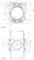
- the flow meter 1 has excitation coils 2 and a core 3.
- the coils 2 and the core 3 form an electromagnet which generates a magnetic field in a measuring tube 4.
- the core 3 consists of two molded parts 5, each of which has a pole 6.
- the core 3 surrounds the measuring tube 4, the poles 6 being arranged diametrically opposite one another with respect to the measuring tube 4.
- Each pole 6 is surrounded by one of the coils 2.
- the molded parts 5 are designed as X-cores and each have four inferences 7 designed as zygomatic bones, which rest against those of the other molded part 5 in a parting plane 8 and thus produce the magnetic flux from one pole 6 to the other within the core 3.
- both molded parts 5 are mirror-symmetrical, the axis of the measuring tube 4 being in the parting plane 8 and, accordingly, a simple assembly of the flow measuring device 1 being made possible.
- the coils 2 are used to generate a magnetic field perpendicular to the direction of movement of the liquid.
- a voltage proportional to the speed is induced perpendicular to the direction of movement and perpendicular to the magnetic field, which voltage is tapped and evaluated with the aid of the electrodes 9.
- the evaluation circuit is not shown.
- the use of a shaped core 3 allows a very variable design.
- the width of the flow measuring device 1, as can be seen in FIG. 3, is only determined by the transverse extent of the coil 2, which is in particular due to the design of the molded parts 5 as X-cores. This allows the construction of a very narrow flow meter 1.
- there is a very simple assembly of the flow meter 1 since the core 3 in the parting plane 8 makes it easy to insert the measuring tube 4 is possible so that flanges or other connecting elements can be positioned on the measuring tube before the flow meter 1 is assembled.
- FIG. 4a shows an M-core, which is preferably formed in one piece from a molded part 5 for a measuring tube 4 with small nominal widths.
- the molded part can, however, as indicated here, be divided in the axial plane of the measuring tube 4.
- FIG. 4b shows that the M core has only two inferences 7.
- Figure 5a shows a two-part shell core.
- the core 5 forms a circular cylinder arranged perpendicular to the axis of the measuring tube 4.
- this embodiment has large-scale conclusions 7 in cross section. This ensures a good return of the magnetic field.
- a very simple embodiment variant results from a U-shape of the core according to FIG. 6a.
- This embodiment in particular enables easy assembly, since the electromagnet can be pushed laterally onto the measuring tube.
- this embodiment can be formed either by a simple U-core with a yoke 7 or also by a half X-core (according to FIGS. 1 to 3) with two yokes 7.
- the half X-core has the advantage that the extension of the electromagnet is determined at least in one direction by the extension of the coil 2.
- FIG. 7a shows an embodiment which is particularly suitable for measuring tubes 4 with large nominal widths.
- the poles 6 have pole shoes 11, which are adapted to the outer contour of the measuring tube 4. This leads to a particularly good guidance of the magnetic field.
- the lower molded part 5 is designed so that the coil 2 is designed as a saddle coil. This allows a particularly space-saving construction of the electromagnet.
- a conventional solenoid 2 as shown in the upper half, can also be used.
- the core can have two or four inferences.
- the core 3 can be constructed from several molded parts or from molded parts in combination with layered laminated cores.
- FIG. 7b shows that in this embodiment, comparable to the X core, four inferences 7 ensure good magnetic inference.
Landscapes
- Physics & Mathematics (AREA)
- Engineering & Computer Science (AREA)
- Power Engineering (AREA)
- Electromagnetism (AREA)
- Fluid Mechanics (AREA)
- General Physics & Mathematics (AREA)
- Measuring Volume Flow (AREA)
Applications Claiming Priority (2)
| Application Number | Priority Date | Filing Date | Title |
|---|---|---|---|
| DE19914114137 DE4114137A1 (de) | 1991-04-30 | 1991-04-30 | Durchflussmessgeraet |
| DE4114137 | 1991-04-30 |
Publications (1)
| Publication Number | Publication Date |
|---|---|
| EP0511595A1 true EP0511595A1 (fr) | 1992-11-04 |
Family
ID=6430704
Family Applications (1)
| Application Number | Title | Priority Date | Filing Date |
|---|---|---|---|
| EP92106986A Withdrawn EP0511595A1 (fr) | 1991-04-30 | 1992-04-24 | Débitmètre |
Country Status (2)
| Country | Link |
|---|---|
| EP (1) | EP0511595A1 (fr) |
| DE (1) | DE4114137A1 (fr) |
Cited By (7)
| Publication number | Priority date | Publication date | Assignee | Title |
|---|---|---|---|---|
| ES2065861A1 (es) * | 1993-05-25 | 1996-07-16 | Contadores De Agua De Zaragoza | Organo medidor magnetico para contadores de fluidos. |
| WO1997041407A1 (fr) * | 1996-04-26 | 1997-11-06 | Caledonian Control Technology Limited | Debitmetres electromagnetiques |
| RU2187075C1 (ru) * | 2001-03-16 | 2002-08-10 | Государственное предприятие "Всероссийский научно-исследовательский институт по эксплуатации атомных электростанций" | Датчик расходомера |
| WO2006122878A1 (fr) * | 2005-05-16 | 2006-11-23 | Endress+Hauser Flowtec Ag | Debitmetre a induction magnetique et tube de mesure pour un debitmetre de ce type |
| US7798015B2 (en) | 2005-05-16 | 2010-09-21 | Endress + Hauser Flowtec Ag | Magneto-inductive flowmeter and measuring tube for such |
| WO2015036187A3 (fr) * | 2013-09-11 | 2015-06-25 | Endress+Hauser Flowtec Ag | Débitmètre à induction magnétique, noyau de bobine et bobine de champ |
| EP3436786B1 (fr) * | 2016-03-31 | 2022-05-04 | Micro Motion, Inc. | Ensemble corps d'écoulement de débitmètre magnétique en polymère |
Families Citing this family (3)
| Publication number | Priority date | Publication date | Assignee | Title |
|---|---|---|---|---|
| DE4307424C2 (de) * | 1993-03-09 | 1997-07-31 | Mat Mischanlagentechnik Gmbh | Regelverfahren zur kontinuierlichen Herstellung einer homogenen Dispersion, insbesondere Suspension sowie zugehörige Vorrichtung |
| DE102005063150A1 (de) * | 2005-12-30 | 2007-07-05 | Endress + Hauser Flowtec Ag | Magnetisch-induktiven Durchflußmesser |
| DE102015109747A1 (de) * | 2015-06-18 | 2016-12-22 | Endress+Hauser Flowtec Ag | Magnetisch-induktives Durchflussmessgerät |
Citations (6)
| Publication number | Priority date | Publication date | Assignee | Title |
|---|---|---|---|---|
| US3636764A (en) * | 1969-10-30 | 1972-01-25 | Statham Instrument Inc | Electromagnet for blood flowmeters and the like |
| US3827298A (en) * | 1971-10-29 | 1974-08-06 | Hitachi Ltd | Electromagnetic flow meter |
| WO1986005873A1 (fr) * | 1985-03-27 | 1986-10-09 | Rheometron Ag | Transducteur pour debitmetre magnetique inducteur |
| EP0228883A1 (fr) * | 1985-12-27 | 1987-07-15 | Aichi Tokei Denki Co., Ltd. | Dispositif pour générer un champ magnétique pour un débitmètre électromagnétique de type à aimantation résiduelle |
| DE4019237A1 (de) * | 1989-06-16 | 1990-12-20 | Hitachi Ltd | Elektromagnetischer durchflussmesser |
| EP0418033A1 (fr) * | 1989-09-12 | 1991-03-20 | Kabushiki Kaisha Toshiba | Débitmètre électromagnétique |
-
1991
- 1991-04-30 DE DE19914114137 patent/DE4114137A1/de not_active Withdrawn
-
1992
- 1992-04-24 EP EP92106986A patent/EP0511595A1/fr not_active Withdrawn
Patent Citations (6)
| Publication number | Priority date | Publication date | Assignee | Title |
|---|---|---|---|---|
| US3636764A (en) * | 1969-10-30 | 1972-01-25 | Statham Instrument Inc | Electromagnet for blood flowmeters and the like |
| US3827298A (en) * | 1971-10-29 | 1974-08-06 | Hitachi Ltd | Electromagnetic flow meter |
| WO1986005873A1 (fr) * | 1985-03-27 | 1986-10-09 | Rheometron Ag | Transducteur pour debitmetre magnetique inducteur |
| EP0228883A1 (fr) * | 1985-12-27 | 1987-07-15 | Aichi Tokei Denki Co., Ltd. | Dispositif pour générer un champ magnétique pour un débitmètre électromagnétique de type à aimantation résiduelle |
| DE4019237A1 (de) * | 1989-06-16 | 1990-12-20 | Hitachi Ltd | Elektromagnetischer durchflussmesser |
| EP0418033A1 (fr) * | 1989-09-12 | 1991-03-20 | Kabushiki Kaisha Toshiba | Débitmètre électromagnétique |
Non-Patent Citations (2)
| Title |
|---|
| PATENT ABSTRACTS OF JAPAN vol. 12, no. 450 (C-547)25. November 1988 & JP-A-63 176 446 ( TOKIN CORP ) 20. Juli 1988 * |
| PATENT ABSTRACTS OF JAPAN vol. 7, no. 20 (M-188)26. Januar 1983 & JP-A-57 174 401 ( FUJITSU ) 27. Oktober 1982 * |
Cited By (7)
| Publication number | Priority date | Publication date | Assignee | Title |
|---|---|---|---|---|
| ES2065861A1 (es) * | 1993-05-25 | 1996-07-16 | Contadores De Agua De Zaragoza | Organo medidor magnetico para contadores de fluidos. |
| WO1997041407A1 (fr) * | 1996-04-26 | 1997-11-06 | Caledonian Control Technology Limited | Debitmetres electromagnetiques |
| RU2187075C1 (ru) * | 2001-03-16 | 2002-08-10 | Государственное предприятие "Всероссийский научно-исследовательский институт по эксплуатации атомных электростанций" | Датчик расходомера |
| WO2006122878A1 (fr) * | 2005-05-16 | 2006-11-23 | Endress+Hauser Flowtec Ag | Debitmetre a induction magnetique et tube de mesure pour un debitmetre de ce type |
| US7798015B2 (en) | 2005-05-16 | 2010-09-21 | Endress + Hauser Flowtec Ag | Magneto-inductive flowmeter and measuring tube for such |
| WO2015036187A3 (fr) * | 2013-09-11 | 2015-06-25 | Endress+Hauser Flowtec Ag | Débitmètre à induction magnétique, noyau de bobine et bobine de champ |
| EP3436786B1 (fr) * | 2016-03-31 | 2022-05-04 | Micro Motion, Inc. | Ensemble corps d'écoulement de débitmètre magnétique en polymère |
Also Published As
| Publication number | Publication date |
|---|---|
| DE4114137A1 (de) | 1992-11-05 |
Similar Documents
| Publication | Publication Date | Title |
|---|---|---|
| EP0649005B1 (fr) | Capteurs de débimètre électromagnétique | |
| DE2424131C3 (de) | Drossel | |
| DE69423867T2 (de) | Gleichstromsensor | |
| DE69503336T2 (de) | Linearantrieb | |
| DE69015526T2 (de) | Elektromagnetischer Durchflussmesser. | |
| EP2463869A1 (fr) | Composant inductif doté de propriétés de noyau améliorées | |
| DE102008035740A1 (de) | Magnetisch induktiver Durchflussmesser mit einer kombinierte magnetische Flussleitmittel umfassenden Elektromagenteinheit | |
| EP1756531B1 (fr) | Capteur de debit a induction magnetique | |
| DE102015101211A1 (de) | Drossel | |
| DE2040682B2 (de) | Induktiver durchflussmesser mit einem in einer vom medium durchstroemten rohrleitung zwischen gegenflanschen deren benachbarter rohrleitungsteile loesbar gehaltenen messrohr aus isolierendem kunstharz | |
| DE2918483C2 (de) | Meßwandler zum potentialfreien Messen von Strömen oder Spannungen | |
| EP1106974B1 (fr) | Débitmètre magnéto-inductif | |
| EP0511595A1 (fr) | Débitmètre | |
| DE3688181T2 (de) | Verfahren zur herstellung eines magnetkreises mit schwachem magnetischem streufeld, insbesondere fuer einen kathodenstrahlrohr speisenden hochspannungstransformator. | |
| EP0069865B1 (fr) | Tête mobile électrodynamique | |
| DE102008035724A1 (de) | Magnetisch induktiver Durchflussmesser mit einer magnetische Flussleitmittel aus einem Materialverbund umfassenden Elektromagneteinheit | |
| EP2479541B1 (fr) | Circuit magnétique pour un débimètre électro-magnétique | |
| EP2867906B1 (fr) | Composant inductif | |
| DE102004063020B4 (de) | Magnetisch-induktives Durchflußmeßgerät | |
| DE2603367C3 (de) | Magnetischer Tonabnehmer | |
| DE102009001413A1 (de) | Spulenanordnung für ein magnetisch induktives Durchflussmessgerät | |
| EP1048932A1 (fr) | Capteur magnétique de position ainsi que procédé pour sa fabrication et son utilisation | |
| DE2925654A1 (de) | Weggeber | |
| DE3235033A1 (de) | Induktiver messwertgeber zur umwandlung der linearen hubbewegungen eines fuehlers mechanischer messgeraete in elektrische messsignale | |
| DE10322082A1 (de) | Magnetisch-induktiver Durchflußaufnehmer |
Legal Events
| Date | Code | Title | Description |
|---|---|---|---|
| PUAI | Public reference made under article 153(3) epc to a published international application that has entered the european phase |
Free format text: ORIGINAL CODE: 0009012 |
|
| AK | Designated contracting states |
Kind code of ref document: A1 Designated state(s): DE DK FR GB IT NL SE |
|
| 17P | Request for examination filed |
Effective date: 19921208 |
|
| 17Q | First examination report despatched |
Effective date: 19940321 |
|
| STAA | Information on the status of an ep patent application or granted ep patent |
Free format text: STATUS: THE APPLICATION IS DEEMED TO BE WITHDRAWN |
|
| 18D | Application deemed to be withdrawn |
Effective date: 19950617 |