EP0511615A1 - Plate-forme de travail pour coffrage de poteaux - Google Patents
Plate-forme de travail pour coffrage de poteaux Download PDFInfo
- Publication number
- EP0511615A1 EP0511615A1 EP92107151A EP92107151A EP0511615A1 EP 0511615 A1 EP0511615 A1 EP 0511615A1 EP 92107151 A EP92107151 A EP 92107151A EP 92107151 A EP92107151 A EP 92107151A EP 0511615 A1 EP0511615 A1 EP 0511615A1
- Authority
- EP
- European Patent Office
- Prior art keywords
- working platform
- formwork
- fastening device
- recess
- carrier
- Prior art date
- Legal status (The legal status is an assumption and is not a legal conclusion. Google has not performed a legal analysis and makes no representation as to the accuracy of the status listed.)
- Granted
Links
- 238000009415 formwork Methods 0.000 claims description 113
- 230000001681 protective effect Effects 0.000 claims description 8
- 239000004567 concrete Substances 0.000 claims description 4
- 239000000725 suspension Substances 0.000 claims description 4
- 238000009416 shuttering Methods 0.000 claims 1
- 239000011150 reinforced concrete Substances 0.000 description 3
- 238000005452 bending Methods 0.000 description 2
- 238000010276 construction Methods 0.000 description 2
- 230000008030 elimination Effects 0.000 description 1
- 238000003379 elimination reaction Methods 0.000 description 1
- 230000000284 resting effect Effects 0.000 description 1
Images


Classifications
-
- E—FIXED CONSTRUCTIONS
- E04—BUILDING
- E04G—SCAFFOLDING; FORMS; SHUTTERING; BUILDING IMPLEMENTS OR AIDS, OR THEIR USE; HANDLING BUILDING MATERIALS ON THE SITE; REPAIRING, BREAKING-UP OR OTHER WORK ON EXISTING BUILDINGS
- E04G17/00—Connecting or other auxiliary members for forms, falsework structures, or shutterings
- E04G17/002—Workplatforms, railings; Arrangements for pouring concrete, attached to the form
-
- E—FIXED CONSTRUCTIONS
- E04—BUILDING
- E04G—SCAFFOLDING; FORMS; SHUTTERING; BUILDING IMPLEMENTS OR AIDS, OR THEIR USE; HANDLING BUILDING MATERIALS ON THE SITE; REPAIRING, BREAKING-UP OR OTHER WORK ON EXISTING BUILDINGS
- E04G13/00—Falsework, forms, or shutterings for particular parts of buildings, e.g. stairs, steps, cornices, balconies foundations, sills
- E04G13/02—Falsework, forms, or shutterings for particular parts of buildings, e.g. stairs, steps, cornices, balconies foundations, sills for columns or like pillars; Special tying or clamping means therefor
Definitions
- the invention relates to a work platform for a concrete formwork at a corner, in particular for a column formwork, with a recess provided in the work platform, which is delimited by edges converging at a corner.
- Known work platforms such as shown in the brochure "NOE column formwork", stand 01.90 from NOE-Schaltechnik, consist of two platforms that are placed next to each other and thus result in a work platform that is L-shaped in plan view.
- support elements e.g. Diagonal supports that are supported on the outside of the formwork.
- the known work platforms consist of many and bulky individual parts, which require a corresponding amount of space during transport and require several operations when loading or unloading. Fastening these work platforms to the formwork is also complex and time-consuming. If one of the parts is not available, the work platform cannot be set up.
- the object of the invention is to provide a working platform for formwork in a corner that does not require any supporting elements.
- This object is achieved in that the work platform around the corner is integrally rigid and that at least one first and one second fastening device is provided on one edge and at least one third fastening device is provided on the other edge.
- the work platform consists essentially of one part due to the elimination of the support elements, and can therefore be quickly attached to a formwork and takes up little transport space.
- At least one fastening device is movable in the plane of the work platform arranged, preferably rigid from the work platform, for example, with the help of a carrier.
- This embodiment is particularly advantageous for adjustable column formwork which is constructed on the windmill principle. Regardless of the size of the column cross-sectional area to be shuttered, the area of the work platform always has the same shape and size; the outer edges of the work platform are always continuous and without offset; Guard rails attached to the outer edges of the work platform are also continuous, there are no gaps between the guard rails.
- This work platform according to the invention can be attached to column formwork, the cross section of which is larger than the recess of the work platform, that is to say to column formwork in which the width of one side of the column is greater than the length of the edge of the recess.
- this embodiment is also suitable for formwork of columns, the cross section of which is smaller than the recess of the working platform.
- a corner of the formwork can rest on the corner of the work platform, which form the two edges of the recess with one another.
- the work platform can also be attached to a smaller cross-section so that the formwork corner does not rest on the corner of the work platform that forms the two edges of the recess with each other, but is at a distance from this corner.
- the third fastening device on the carrier is moved so far into the recess of the working platform that it comes to lie over the upper end of the formwork element and can be fastened there. Due to the mobility of the third fastening device, the
- Work platform can also be attached to the upper end of column formwork, which do not have a rectangular cross section, but for example a triangular or polygonal cross section or a round cross section.
- the third fastening device has to be moved so far into the recess in the working platform that it can be fastened to the upper end of a formwork element.
- the third fastening device can be rigidly fastened to the free end of the carrier.
- the carrier is held in the work platform in a rigid manner.
- the carrier can also protrude with its free end into the recess and be rigidly connected to the work platform and the fastening device can be guided displaceably along this carrier.
- the working platform according to the invention is not only suitable for fastening to the upper end of column formwork, but also for fastening to formwork for another corner of a building, namely wherever formwork elements are fastened to one another at an angle.
- the formwork elements can be arranged according to the "windmill principle" or formwork elements can be provided whose width corresponds to the width of the flat surfaces to be formworked of a column to be formworked. In this case, the edges of the formwork elements do not protrude beyond the column to be formworked, as in the formwork according to the "windmill principle".
- the third fastening device can be moved into the recess at a right angle to the edge of the recess of the working platform, on which the fastening device is arranged.
- the support on which the third fastening device is arranged can be fastened to the work platform so as to be pivotable by a certain angle, so that the third fastening device is movable in the recess along a circular arc section in the plane of the work platform.
- the third fastening device is movable parallel to the edge of the recess in the working platform to which it is attached, possibly in addition to a movement possible at right angles to this edge. If the movable fastening device is movable both at right angles and parallel to one edge of the recess, this can be achieved, for example, by the fastening device being fastened to a cross slide.
- the movement of the third fastening device along the one edge of the recess can be realized in one embodiment of the invention in that several guides are provided along the edge of the recess at right angles to this edge in the work platform, which are used optionally for receiving the carrier of the third fastening device and in which the carrier is guided at right angles to the edge of the recess.
- the fastening device is rigidly fastened to one end of the carrier and the carrier itself can be completely pulled out of the guide so that it can be inserted into another guide.
- the aforementioned third fastening device can be used several times in one embodiment of the invention be provided on the edge of the fastening device, for example two, three or more such fastening devices can be provided such that they can be moved into the recess on the same edge of the recess.
- a rigid guide of the carrier of the fastening device can be realized in that the carrier is guided in the work platform in a hollow profile in the manner of a telescope.
- the previous embodiments of the work platform can be developed in such a way that the carrier or the third fastening device can be locked in its respective position.
- edges of the recess in the work platform form a right angle. In other embodiments of the invention, they can also include an angle deviating from a right angle. It is only necessary to ensure that the fastening devices, in particular the third fastening device, the position of which can be chosen as desired within the recess in embodiments of the invention, are arranged such that they absorb all the tilting moments which occur when the working platform is loaded.
- the edges of the recess in the working platform are approximately the same length as those end faces of formwork elements to which the working platform can be fastened.
- the work platform can be designed so that the angle between the edges of the recess of the work platform is the same size as the angle of the corner of the formwork for which the work platform is intended.
- the work platform according to the invention is the cross section to be shuttered and adapted to the formwork elements used. As a result, it can be particularly easily attached to the designated places on the formwork.
- the working platform leaves parting planes or joints at which the formwork half to which the working platform is fastened is connected to the rest of the formwork when it is shuttered and taken apart again when stripping.
- the working platform does not hinder the stripping or stripping. It can remain connected as a unit to the corresponding part of the formwork when formwork is being removed and removed.
- the fastening devices of the working platform on the formwork are designed as suspension points for a hoist.
- the working platform can be attached to a crane, for example, together with the part of the formwork to which it is attached.
- the unit consisting of the working platform and the part of the formwork to which it is attached takes a slight inclination to the vertical plane when floating, which makes it easier to form and remove the formwork.
- the work platform is mirror-symmetrical to its horizontal center plane.
- the work platform can also be used in reverse, which means that it can be used on column formwork based on the windmill principle, regardless of its direction of rotation.
- This embodiment can be developed in such a way that fastening parts for guardrails are designed such that the guardrails can be attached to both accessible surfaces of the work platform.
- the guardrails of the work platform are all constructed identically.
- Figure 1 shows a bending and torsionally rigid work platform 1, which has the shape of an L with legs of the same length in plan view.
- three fastening devices 2, 3, 4 are provided, two of which 2, 3 are arranged fixedly on an edge 5 of a recess 7 of the work platform 1.
- the third fastening device 4 is located on a carrier 6, which is in the plane of the work platform 1 in the recess 7 at right angles to another edge 8 of the recess 7 is slidably mounted.
- the carrier 7 is telescopic and rigid in every possible position in the work platform 1 and can be locked. The extension of the carrier 7 is limited.
- guard rails 9 can be inserted into holding parts 10 from both sides.
- the protective railings 9 can be secured in a known manner, for example by means of spring plugs.
- the lower ends 11 of the railing supports 36, 37 of the protective railing 9 protrude so far downward beyond the working platform 1 that an inadvertent lifting of the protective railing 9 is excluded with certainty and the legal provisions are complied with.
- four guardrails can be used which have the same dimensions as the guardrails on the front edges of the work platform 1.
- the work platform has 1 in this case six identical guardrails.
- the working platform 1 is fastened to the fastening devices 2, 3, 4 on the end faces of two formwork elements 14, 15 by means of three fastening screws, the head of which is designed as a ring.
- the two formwork elements 14, 15 form half of a column formwork for a column to be cast from reinforced concrete with a rectangular cross-section.
- the column formwork consists of four formwork elements 14, 15, 16, 17, which are arranged in the so-called windmill principle.
- the formwork elements 14, 15, 16, 17 are wider than the side surfaces of the column cross-section and one end face of a formwork element 14, 15, 16, 17 lies on the formwork surface of one adjacent formwork elements 14, 15, 16, 17, whereas the opposite end faces of the formwork elements 14, 15, 16, 17 protrude beyond the side surfaces of the column.
- Each two interconnected formwork elements 14, 15 and 16, 17 form a column formwork half.
- the rings of the fastening screws also serve as crane suspension points for the column formwork half to which the working platform 1 is attached.
- the work platform 1 is mirror-symmetrical to its horizontal center plane. This means that it can be turned and can be used for column formwork based on the windmill principle, regardless of the direction of rotation of the column formwork.
- the guardrails 9 can be inserted into the holding parts 10 from both sides.
- Two formwork elements 14, 15 and 16, 17 are assembled on the floor to form a column formwork half.
- the working platform 1 is fastened to one half 14, 15 of the column formwork and the protective railings 9 are attached to it.
- the two halves of the column formwork are then attached one after the other, for example to a crane, erected and brought to the place where the column formwork is needed. Due to this suspension, the column formwork half in the floating state assumes an inclined position in which the lower part of the formwork elements 14, 15 is inclined "inwards", ie in the direction of a reinforced concrete column to be cast later.
- the inclined position makes it particularly easy to assemble the two column formwork halves.
- the working platform 1 does not project over parting planes 18, 19, on which the two column formwork halves composed of two formwork elements 14, 15 or 16, 17 are connected when formworking and disassembled again when stripping, i.e. not over the formwork levels of the two formwork elements 14, 17 of the two column formwork halves against which the formwork elements 16, 15 of the other formwork halves rest. This would be a hindrance when striking and stripping.
- Tilting moments due to loading of the working platform at the edges 12, 13 facing away from the recess 7 are mainly absorbed by the fastening device 4, 3 which is the most distant from the respective edge 12, 13.
- a working platform that runs completely around a cast concrete column is normally not required. If a working platform 1 is not sufficient, two working platforms 1 can be attached to a column formwork. In this case, a work platform 1 is attached to a column formwork half composed of two formwork elements 14, 15 and 16, 17, respectively.
- the gap between the edge 8 of the recess 7 of the work platform 1, on which the carrier 6 is located, and the formwork element 14 located on this edge 8 can be made by means of a square timber fastened to the end face of this formwork element 14 and a board fastened to this square timber the work platform 1 overlaps and rests on it, can be bridged.
- a so-called drag plate can also be used: the drag plate is supported on one side on the end face of the formwork element 14 and is fastened to this and possibly to the fastening device 4 of the carrier 6. The other side of the drag plate lies on the work platform 1.
- the rigid work platform 1 is connected without support elements to the formwork half composed of two formwork elements 14, 15 in a stable and resilient manner.
- the three fastening devices 2, 3, 4 are arranged approximately at right angles to one another and are at a sufficient distance from one another.
- a load on the work platform 1 at any point acts as a moment about an imaginary tilt axis by two adjacent fastening devices 2, 3 or 2, 4 of the work platform 1, which is received by the third fastening device 4 or 3.
- a toe board 28 is fastened to two railing supports 36, 37 in the plane defined by this, the lower end face of which rests on the holding parts 10 when the protective railing 9 is inserted, and the lower inner edge 39 of which rests on an upper outer edge 40 of the work platform 1.
- the platform of the work platform 1 has a supporting grate, e.g. B. from tubes or beams with a different cross-section, which gives the work platform 1 the required bending resistance and possibly torsion resistance.
- This grate is covered and connected on both sides with a flat, walkable covering.
- FIG. 2 schematically shows an embodiment of the invention in which rectangular tubes 20, 21 are arranged in the work platform 1 at a distance from one another orthogonally to the edge 8 of the recess 7 in the work platform 1.
- the carrier 6 of the fastening device 4 can be inserted, which is guided displaceably in the relevant rectangular tube 20, 21.
- the carrier 6 is slidably guided in the rectangular tube 21 and pulled out into the recess 7 to such an extent that the fastening device 4 comes to rest on a formwork element 22, on the upper end face of which the fastening device 4 is fastened.
- the fastening devices 2 and 3 engage in the upper edge of a formwork element 23 which is fastened to the formwork element 22.
- the working platform 1 is fastened with the fastening devices 2 and 3 at the upper edge of the column formwork that the parting plane 26 is not covered by the working platform 1, because this would occur during construction and during dismantling interfere with the column formwork.
- the formwork element 22 is arranged at a certain distance from the edge 8 of the recess 7 of the work platform 1, so that the parting plane 26 is not covered by the work platform 1, which is why the carrier 6 consists of one Guide and bracket serving rectangular tube 21 must be pulled out a bit. If the column cross section were wider parallel to the edge 8, the support 6 could also be in the rectangular tube 20 is inserted and guided and held by this.
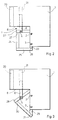
- FIG. 3 shows schematically from above the embodiment of the work platform 1 already explained in FIG. 2 in use with a formwork for a triangular column cross section. It can be seen that also by inserting the carrier 6 into the rectangular tube 21, that is to say by laterally displacing the fastening device 4 along the edge 8 and pulling out the carrier 6 at right angles to the edge 8 of the recess 7 in the work platform 1, the fastening device 4 at the top End of a formwork element 28 of a formwork for a triangular column cross section can be attached. The fastening devices 2 and 3 engage in the upper edge of a formwork element 29. During assembly and disassembly, the formwork is separated at parting levels 30, 31. The work platform 1 remains attached to the formwork elements 28, 29.
- Fig. 4 shows the application of the embodiment of the working platform 1 shown in Figs. 2 and 3 with laterally displaceable fastening device 4 when used on a formwork for a round column cross-section.
- the two semicircular formwork elements 32, 33 are assembled at parting planes 34, 35.
- the fastening devices 2, 3, 4 in turn engage a formwork half, which here consists of a formwork element 32.
- the attachment of the work platform 1 to this formwork is chosen so that the work platform 1 does not cover the parting planes 34, 35.
- fastening elements can also be used for fastening the working platform 1 to the upper end of a formwork, which in turn are designed in this way can that a crane hook can engage in these fasteners.
- the work platform 1 can be attached not only to the upper end faces of a formwork, but also to the upper edge of the outer surface of the formwork.
- more than one fastening device 4 can also be movably guided in the plane of the work platform 1 or in a plane parallel to it.
- the carrier 6 can also consist of a round tube.
Landscapes
- Engineering & Computer Science (AREA)
- Architecture (AREA)
- Mechanical Engineering (AREA)
- Civil Engineering (AREA)
- Structural Engineering (AREA)
- Forms Removed On Construction Sites Or Auxiliary Members Thereof (AREA)
Applications Claiming Priority (2)
| Application Number | Priority Date | Filing Date | Title |
|---|---|---|---|
| DE4113877 | 1991-04-27 | ||
| DE4113877A DE4113877A1 (de) | 1991-04-27 | 1991-04-27 | Arbeitsbuehne fuer saeulenschalung |
Publications (2)
| Publication Number | Publication Date |
|---|---|
| EP0511615A1 true EP0511615A1 (fr) | 1992-11-04 |
| EP0511615B1 EP0511615B1 (fr) | 1995-01-25 |
Family
ID=6430541
Family Applications (1)
| Application Number | Title | Priority Date | Filing Date |
|---|---|---|---|
| EP92107151A Expired - Lifetime EP0511615B1 (fr) | 1991-04-27 | 1992-04-27 | Plate-forme de travail pour coffrage de poteaux |
Country Status (4)
| Country | Link |
|---|---|
| EP (1) | EP0511615B1 (fr) |
| AT (1) | ATE117759T1 (fr) |
| DE (2) | DE4113877A1 (fr) |
| ES (1) | ES2070547T3 (fr) |
Cited By (3)
| Publication number | Priority date | Publication date | Assignee | Title |
|---|---|---|---|---|
| ES2154512A1 (es) * | 1997-01-27 | 2001-04-01 | Extremadura 2000 De Estructura | Plataforma de encofrado ajustable alrededor del pilar o del encofrado del pilar, para apoyo de figas prefabricadas. |
| ES2349601A1 (es) * | 2008-07-04 | 2011-01-07 | Sistema Tecnicos De Encofrados, S.A. | Panel para encofrado en altura, con plataforma incorporada y utlizacion del mismo. |
| ITPD20120327A1 (it) * | 2012-11-06 | 2014-05-07 | Faresin Building Division S P A | Piattaforma di servizio per casserature per la realizzazione di pilastri in calcestruzzo e simili |
Families Citing this family (1)
| Publication number | Priority date | Publication date | Assignee | Title |
|---|---|---|---|---|
| CN112727079A (zh) * | 2021-01-27 | 2021-04-30 | 北京市住宅产业化集团股份有限公司 | 一种防护一体化的定型组合式模板及施工方法 |
Citations (2)
| Publication number | Priority date | Publication date | Assignee | Title |
|---|---|---|---|---|
| FR2071428A5 (fr) * | 1969-12-29 | 1971-09-17 | Bard Jean | |
| US3617047A (en) * | 1970-06-08 | 1971-11-02 | Burke Concrete Accessories | Concrete column form clamp and method |
Family Cites Families (1)
| Publication number | Priority date | Publication date | Assignee | Title |
|---|---|---|---|---|
| DE7143560U (de) * | 1971-11-19 | 1972-02-10 | Zipf, Kurt, 8702 Zeil | Arbeitspodest fuer masten |
-
1991
- 1991-04-27 DE DE4113877A patent/DE4113877A1/de not_active Withdrawn
-
1992
- 1992-04-27 EP EP92107151A patent/EP0511615B1/fr not_active Expired - Lifetime
- 1992-04-27 ES ES92107151T patent/ES2070547T3/es not_active Expired - Lifetime
- 1992-04-27 DE DE59201255T patent/DE59201255D1/de not_active Expired - Lifetime
- 1992-04-27 AT AT92107151T patent/ATE117759T1/de active
Patent Citations (2)
| Publication number | Priority date | Publication date | Assignee | Title |
|---|---|---|---|---|
| FR2071428A5 (fr) * | 1969-12-29 | 1971-09-17 | Bard Jean | |
| US3617047A (en) * | 1970-06-08 | 1971-11-02 | Burke Concrete Accessories | Concrete column form clamp and method |
Cited By (3)
| Publication number | Priority date | Publication date | Assignee | Title |
|---|---|---|---|---|
| ES2154512A1 (es) * | 1997-01-27 | 2001-04-01 | Extremadura 2000 De Estructura | Plataforma de encofrado ajustable alrededor del pilar o del encofrado del pilar, para apoyo de figas prefabricadas. |
| ES2349601A1 (es) * | 2008-07-04 | 2011-01-07 | Sistema Tecnicos De Encofrados, S.A. | Panel para encofrado en altura, con plataforma incorporada y utlizacion del mismo. |
| ITPD20120327A1 (it) * | 2012-11-06 | 2014-05-07 | Faresin Building Division S P A | Piattaforma di servizio per casserature per la realizzazione di pilastri in calcestruzzo e simili |
Also Published As
| Publication number | Publication date |
|---|---|
| ES2070547T3 (es) | 1995-06-01 |
| DE4113877A1 (de) | 1992-10-29 |
| EP0511615B1 (fr) | 1995-01-25 |
| ATE117759T1 (de) | 1995-02-15 |
| DE59201255D1 (de) | 1995-03-09 |
Similar Documents
| Publication | Publication Date | Title |
|---|---|---|
| DE69408453T2 (de) | Höhenverstellbare Arbeitsvorrichtung | |
| DE202020104198U1 (de) | Baugerüst | |
| EP4538481A1 (fr) | Dispositif pour la fixation de protections contre les chutes à des échafaudages | |
| DE2050516A1 (de) | Senkrecht verstellbare Plattform fur Baugerüste | |
| DE9410466U1 (de) | Fahrbares Baugerüst | |
| WO2009118198A2 (fr) | Dispositif pour démolir des constructions | |
| DE102019111930A1 (de) | Gerüstrahmen, Gerüstsystem, Gerüstsegment und Gerüst | |
| EP0511615B1 (fr) | Plate-forme de travail pour coffrage de poteaux | |
| DE2759088C2 (de) | Klettergerüst mit Kletterschalung zur Herstellung einer Stahlbetonwand | |
| EP0512428A1 (fr) | Plate-forme de travail pour murs ou coffrages | |
| DE3443451C1 (de) | Vorrichtung zum Einrichten einer Stütze | |
| DE2402683C3 (de) | Kletterschalung | |
| DE2949403A1 (de) | Geruest und zugehoeriges querelement | |
| DE3520724A1 (de) | Vorrichtung zum einruesten einer gebaeudeecke | |
| DE9116649U1 (de) | Arbeitsbühne für Säulenschalung | |
| DE29510784U1 (de) | Transportwagen für flächige Schalungselemente | |
| DE1434362B1 (de) | Wandschalung aus Traegerrosten | |
| DE3736320C1 (en) | Apparatus for aligning shuttering panels | |
| DE3911044C2 (fr) | ||
| DE2643582C2 (de) | Vorrichtung zur Längenverstellung von Gerüsten, Stützen o.dgl | |
| DE9201136U1 (de) | Gerät mit einer in ihrer Höhe verstellbaren Arbeitsbühne | |
| DE3501702C1 (de) | Klettergerüst für das Erstellen von gemauerten Schornsteinen | |
| DE2124039C3 (de) | Vorrichtung zum Errichten mindestens eines zylindrischen Rohres innerhalb eines Stützturms | |
| DE1539826C (de) | Tragvorrichtung fur eine Beschickungs maschine eines Kernreaktors | |
| DE3822700A1 (de) | Hilfsvorrichtung zur montage eines lastarmes an einem profiltraeger |
Legal Events
| Date | Code | Title | Description |
|---|---|---|---|
| PUAI | Public reference made under article 153(3) epc to a published international application that has entered the european phase |
Free format text: ORIGINAL CODE: 0009012 |
|
| 17P | Request for examination filed |
Effective date: 19920905 |
|
| AK | Designated contracting states |
Kind code of ref document: A1 Designated state(s): AT DE ES GB IT |
|
| 17Q | First examination report despatched |
Effective date: 19930809 |
|
| GRAA | (expected) grant |
Free format text: ORIGINAL CODE: 0009210 |
|
| ITF | It: translation for a ep patent filed |
Representative=s name: PATRITO BREVETTI |
|
| AK | Designated contracting states |
Kind code of ref document: B1 Designated state(s): AT DE ES GB IT |
|
| REF | Corresponds to: |
Ref document number: 117759 Country of ref document: AT Date of ref document: 19950215 Kind code of ref document: T |
|
| GBT | Gb: translation of ep patent filed (gb section 77(6)(a)/1977) |
Effective date: 19950203 |
|
| REF | Corresponds to: |
Ref document number: 59201255 Country of ref document: DE Date of ref document: 19950309 |
|
| REG | Reference to a national code |
Ref country code: ES Ref legal event code: FG2A Ref document number: 2070547 Country of ref document: ES Kind code of ref document: T3 |
|
| PLBE | No opposition filed within time limit |
Free format text: ORIGINAL CODE: 0009261 |
|
| STAA | Information on the status of an ep patent application or granted ep patent |
Free format text: STATUS: NO OPPOSITION FILED WITHIN TIME LIMIT |
|
| 26N | No opposition filed | ||
| REG | Reference to a national code |
Ref country code: GB Ref legal event code: IF02 |
|
| PGFP | Annual fee paid to national office [announced via postgrant information from national office to epo] |
Ref country code: IT Payment date: 20110324 Year of fee payment: 20 |
|
| PGFP | Annual fee paid to national office [announced via postgrant information from national office to epo] |
Ref country code: ES Payment date: 20110419 Year of fee payment: 20 Ref country code: DE Payment date: 20110423 Year of fee payment: 20 |
|
| PGFP | Annual fee paid to national office [announced via postgrant information from national office to epo] |
Ref country code: GB Payment date: 20110419 Year of fee payment: 20 Ref country code: AT Payment date: 20110429 Year of fee payment: 20 |
|
| REG | Reference to a national code |
Ref country code: DE Ref legal event code: R071 Ref document number: 59201255 Country of ref document: DE |
|
| REG | Reference to a national code |
Ref country code: DE Ref legal event code: R071 Ref document number: 59201255 Country of ref document: DE |
|
| REG | Reference to a national code |
Ref country code: GB Ref legal event code: PE20 Expiry date: 20120426 |
|
| REG | Reference to a national code |
Ref country code: ES Ref legal event code: FD2A Effective date: 20120717 |
|
| PG25 | Lapsed in a contracting state [announced via postgrant information from national office to epo] |
Ref country code: DE Free format text: LAPSE BECAUSE OF EXPIRATION OF PROTECTION Effective date: 20120428 Ref country code: ES Free format text: LAPSE BECAUSE OF EXPIRATION OF PROTECTION Effective date: 20120428 |
|
| PG25 | Lapsed in a contracting state [announced via postgrant information from national office to epo] |
Ref country code: GB Free format text: LAPSE BECAUSE OF EXPIRATION OF PROTECTION Effective date: 20120426 |
|
| REG | Reference to a national code |
Ref country code: AT Ref legal event code: MK07 Ref document number: 117759 Country of ref document: AT Kind code of ref document: T Effective date: 20120427 |