EP0512149B1 - Arbre de pédalier pour une bicyclette - Google Patents
Arbre de pédalier pour une bicyclette Download PDFInfo
- Publication number
- EP0512149B1 EP0512149B1 EP91108733A EP91108733A EP0512149B1 EP 0512149 B1 EP0512149 B1 EP 0512149B1 EP 91108733 A EP91108733 A EP 91108733A EP 91108733 A EP91108733 A EP 91108733A EP 0512149 B1 EP0512149 B1 EP 0512149B1
- Authority
- EP
- European Patent Office
- Prior art keywords
- teeth
- screw ring
- screw
- crank axle
- tool
- Prior art date
- Legal status (The legal status is an assumption and is not a legal conclusion. Google has not performed a legal analysis and makes no representation as to the accuracy of the status listed.)
- Expired - Lifetime
Links
Images




Classifications
-
- B—PERFORMING OPERATIONS; TRANSPORTING
- B62—LAND VEHICLES FOR TRAVELLING OTHERWISE THAN ON RAILS
- B62M—RIDER PROPULSION OF WHEELED VEHICLES OR SLEDGES; POWERED PROPULSION OF SLEDGES OR SINGLE-TRACK CYCLES; TRANSMISSIONS SPECIALLY ADAPTED FOR SUCH VEHICLES
- B62M3/00—Construction of cranks operated by hand or foot
- B62M3/003—Combination of crank axles and bearings housed in the bottom bracket
-
- B—PERFORMING OPERATIONS; TRANSPORTING
- B62—LAND VEHICLES FOR TRAVELLING OTHERWISE THAN ON RAILS
- B62K—CYCLES; CYCLE FRAMES; CYCLE STEERING DEVICES; RIDER-OPERATED TERMINAL CONTROLS SPECIALLY ADAPTED FOR CYCLES; CYCLE AXLE SUSPENSIONS; CYCLE SIDECARS, FORECARS, OR THE LIKE
- B62K19/00—Cycle frames
- B62K19/30—Frame parts shaped to receive other cycle parts or accessories
- B62K19/34—Bottom brackets
-
- Y—GENERAL TAGGING OF NEW TECHNOLOGICAL DEVELOPMENTS; GENERAL TAGGING OF CROSS-SECTIONAL TECHNOLOGIES SPANNING OVER SEVERAL SECTIONS OF THE IPC; TECHNICAL SUBJECTS COVERED BY FORMER USPC CROSS-REFERENCE ART COLLECTIONS [XRACs] AND DIGESTS
- Y10—TECHNICAL SUBJECTS COVERED BY FORMER USPC
- Y10T—TECHNICAL SUBJECTS COVERED BY FORMER US CLASSIFICATION
- Y10T74/00—Machine element or mechanism
- Y10T74/21—Elements
- Y10T74/2164—Cranks and pedals
-
- Y—GENERAL TAGGING OF NEW TECHNOLOGICAL DEVELOPMENTS; GENERAL TAGGING OF CROSS-SECTIONAL TECHNOLOGIES SPANNING OVER SEVERAL SECTIONS OF THE IPC; TECHNICAL SUBJECTS COVERED BY FORMER USPC CROSS-REFERENCE ART COLLECTIONS [XRACs] AND DIGESTS
- Y10—TECHNICAL SUBJECTS COVERED BY FORMER USPC
- Y10T—TECHNICAL SUBJECTS COVERED BY FORMER US CLASSIFICATION
- Y10T74/00—Machine element or mechanism
- Y10T74/21—Elements
- Y10T74/2164—Cranks and pedals
- Y10T74/2165—Cranks and pedals with attached gear
Definitions
- the present invention relates principally to a crank axle according to the preamble of the main claim.
- crank axle units are known (Japanese Utility Model Publication Kokai No. 1989-180394, for example).
- This crank axle unit includes a first screw ring for fitting to an outside wall of one end region of a tubular element and screwing to an inside wall of one end region of a bottom bracket, and a second screw ring for fitting to an outside wall of the other end region of the tubular element and screwing to an inside wall of the other end region of the bottom bracket.
- the two screw rings have grooves defined on outer peripheries thereof to act as engaging portions engageable with a screwing tool. That is, the screw rings are turned by a tool acting on the outer peripheries thereof.
- these engaging portions have extended axial lengths to allow the screw rings to be turned until the screw rings are screwed into the bottom bracket to extents corresponding to predetermined lengths for assembly purposes, and to prevent deformation of the engaging portions of the screw rings due to the reaction to turning and tightening of the screw rings to the limits. Consequently, the screw rings project to relatively large extents from the bottom brackets when the screw rings are assembled to the bottom bracket as designed. Front gears and cranks must therefore be located at relatively remote positions laterally of the bottom bracket to be out of contact with the screw rings.
- a crank axle unit according to the preamble of the main claim is known (FR-623094).
- the first screw ring hereby is not fitted to an outside wall in one end region of the tubular element and is not screwed to an inside wall in one end region of said bottom bracket. Therefore, the screw ring serves not for positioning and fixing the tubular element in said bottom bracket.
- the tubular element itself is in direct contact with the bottom bracket and is responsible for fixing its own position in the bottom bracket.
- crank axle unit By loosening of the screw ring it would not allow the ring member a1 to come out. Therefore, assembling and disassembling of the crank axle unit requires skill.
- An object of the present invention is to provide an improved crank axle unit for a bicycle and an improved technique of assembling the crank axle unit to a bicycle frame.
- the present invention provides a crank axle according to the preamble of the main claim being characterised with the characterising features thereof.
- the tool When screwing the first and second screw rings into the bottom bracket with a tightening tool, the tool acts on the engaging device formed on the inside wall of each screw ring and allows the easy assembling of the unit. It is therefore possible even to insert each screw ring completely into the bottom bracket as necessary. This allows front gears and cranks attached to the crank axle to be disposed inwardly toward the bottom bracket, i.e. toward the bicycle frame. Even then, sufficiently large areas of interaction between the engaging devices and tool may be secured to avoid deformation of the engaging devices due to a reaction to the tightening force.
- the first screw ring is formed of a metal and the second screw ring formed of plastic, the first and second engaging devices comprising teeth formed on the inside walls of the first and second screw rings, respectively, the pitch of the teeth of the first engaging device being a product of the pitch of the teeth of the second tool engaging device multiplied by an integer (i.e. twice or more).
- a tightening tool may be prepared which includes opposite teeth arranged on an outside wall thereof at the pitches of the teeth of the second engaging device, the opposite teeth being shaped such that a plurality of opposite teeth fit into a region between adjacent teeth of the first engaging device.
- the second screw ring formed of a weak material may be tightened by means of a force-acting area several times larger than when tightening the first screw ring. This feature allows the configuration of each tool engaging device to be determined in an optimal way where the two screw rings having different material strengths are used.
- the invention concerns also a tightening tool for positioning and fixing a crank axle unit as claimed in the main claim, according to claim 7.
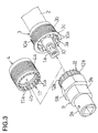
- a crank axle unit for a bicycle comprises a unit body including a crank axle 1 and a tubular element 2, and a first screw ring 3 and a second screw ring 4 mounted on opposite ends of the tubular element 2.
- This crank axle unit is assembled to a bicycle frame by means of a bottom bracket 5 as shown in Fig. 2.
- the crank axle 1 carries right and left cranks 6a and 6b on opposite ends, and front gears 7 on one end thereof.
- crank axle 1 extends through the tubular element 2 and is rotatably supported therein through balls 8.
- the crank axle 1 is positioned and retained relative to the tubular element 2 by cooperation of these balls 8 and ring grooves defined circumferentially of the crank axle 1 to receive the balls 8.
- the opposite ends of the crank axle 1 define crank connections 1a in form of square shafts to which the cranks 6a and 6b are attached for turning together with the crank axle 1.
- the tubular element 2 defines an annular groove 2a peripherally of an intermediate region thereof for reducing its weight.
- the first screw ring 3 includes an annular stopper 3a projecting from an inside wall thereof, and a flange-shaped abutment 3c projecting from an outside wall at an outer end of the first screw ring 3. Further, the first screw ring 3 includes a threaded portion 3b defined over a substantial length peripherally thereof.
- the first screw ring 3 is fitted to the tubular element 2 to the extent that the stopper 3a contacts an end face of the tubular element 2, and securely fixed to the tubular element 2 such as by press fit.
- the tubular element 2 is in engagement through the threaded portion 3b of the first screw ring 3 with a threaded portion formed on an inside wall at one end of the bottom bracket 5.
- the first screw ring 3 is positioned relative to the bottom bracket 5 by the abutment 3c.
- the second screw ring 4 securely fitted on the other end of the tubular element 2 defines a threaded portion 4a peripherally and substantially over an entire length thereof to be engageable with an inside wall at the other end of the bottom bracket 5.
- the second screw ring 4 also includes a stopper 4b projecting inwardly from an inside wall thereof.
- the stopper 4b is cooperable with an end face of the tubular element 2 to positively maintain the tubular element 2 between the first screw ring 3 and second screw ring 4. That is, the first screw ring 3 fixed to the crank axle unit body is screwed into the bottom bracket 5 from the side at which the front gears 7 are mounted, until the abutment 3c of the first screw ring 3 contacts the end face of the bottom bracket 5.
- the first and second screw rings 3 and 4 include a first and a second engaging portions 10 and 11 defined on inside walls in end regions thereof, respectively, on which a screwing tool 9 acts to screw the two screw rings 3 and 4 into the bottom bracket 5.
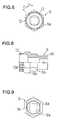
- the first engagement portion 10 includes a plurality of projections or teeth 10a arranged at pitches P1 circumferentially of the first screw ring 3 as shown in Fig. 4.
- the second engagement portion 11 includes a plurality of projections or teeth 11a arranged at pitches P2 circumferentially of the second screw ring 4 as shown in Fig. 5.
- the tool 9 has a tubular portion 12 for acting on the screw rings, which includes a plurality of projections or teeth 12a arranged at the same pitches P2 as in the second screw ring 4 circumferentially on an outside wall of the tubular portion 12.
- the pitches and shapes of the teeth 12 of the tool 9 and the teeth 10a and 11a of the two ring screws 3 and 4 are suitably determined, so that the same tool 9, that is the teeth 12a of the same force-applying portion 12 may be used to screw tight the screw rings 3 and 4.
- the abutment 3c of the first screw ring 3 must have a small axial length to minimize the extent to which the first screw ring 3 project from the bottom bracket 5 because of the abutment 3c and allow the crank 6b and front gears 7 to be arranged as inwardly as possible. In spite of this, the abutment 3c must have a sufficient strength for position setting through contact with the bottom bracket 5.
- the first screw ring 3 is formed of a metal, for example.
- the second screw ring 4 which may be less strong than the first screw ring 3 is formed of plastic, for example, to be as light as possible and manufactured at low cost.
- the pitch P1 is the product of the pitch P2 multiplied by an integer, so that the number of teeth 11a of the second screw ring 4 corresponds to the product of the number of teeth 10a of the first screw ring 3 multiplied by the integer.
- teeth 10a, 11a and 12a have such shaped that one of the teeth 12a fits into a space between two adjacent teeth 11a while a plurality of teeth 12a fit into a space between two adjacent teeth 10a. This relationship will be described in outline with reference to Fig. 7.
- Fig. 7 shows the pitch P1 of the teeth 10a of the first screw ring 3 being twice the pitch P2 of the teeth 11a of the second screw ring 4.
- the engagement portion 11 of the second screw ring 4 meshes with the opposite engagement portion or force-applying portion 12 of the tool 9 as an ordinary gear pair. That is, a tooth 12a has a length t1 substantially corresponding to that of a tooth bottom between adjacent teeth 11a, and a tooth 11a has a length S1 substantially corresponding to that of a tooth bottom between adjacent teeth 12a.
- a tooth 10a of the first screw ring 3 has a length substantially corresponding to the length S1 of the tooth bottom between adjacent teeth 12a.
- a tooth bottom between adjacent teeth 12a of the first screw ring 3 has a length substantially corresponding to S1+2t1 which is the sum of the length S1 of the tooth bottom between teeth 12a and twice the length t1 of a tooth 12a.
- the second screw ring 4 may be tightened by means of larger engagement areas than the first screw ring 3.
- the first screw ring 3 includes only a necessary number of teeth to avoid an undue increase in manufacturing cost and to secure the largest possible distance between adjacent teeth for facility of removal of earth and dust accumulating therein.
- one of the threaded portions 3b and 4a of the first and second gear rings 3 and 4 is formed as a right-handed screw and the other a left-handed screw so that the screw rings 3 and 4 do not readily become loose with rotation of the crank axle 1.
- the screw rings 3 and 4 are constructed such that the engagement portion 10 or 11 where teeth 10a or 11a are defined has an inside diameter exceeding an outside diameter of an inward end of a boss of the crank 6a or 6b. This construction allows the inward ends of the bosses of the cranks to enter the engagement portions 10 and 11, so that cranks 6a and 6b and front gears 7 are located inwardly with respect to the bicycle frame.
- the tool 9 may advantageously comprise a first tightening portion 9a having a hexagon section, a second tightening portion 9b having a track-shaped section, for engaging a wrench or a spanner, and a third tightening portion 9c defining a square bore for engaging a pneumatic screw driver.
Landscapes
- Engineering & Computer Science (AREA)
- Mechanical Engineering (AREA)
- Chemical & Material Sciences (AREA)
- Combustion & Propulsion (AREA)
- Transportation (AREA)
- Gears, Cams (AREA)
- Clamps And Clips (AREA)
Claims (8)
- Arbre de pédalier (1) monté dans un moyeu (5) assemblé à la base d'un cadre de bicyclette, comprenant :- un élément tubulaire (2) entourant et supportant en rotation l'arbre de pédalier (1), ledit élément tubulaire (2) étant entouré par ledit moyeu (5) et,- une première (3) et une seconde (4) bagues filetées, de façon que la première bague (3) comprenne un premier moyen de prise pour outil (10) formé sur une paroi intérieure à une extrémité de cette bague, et ladite seconde bague (4) comprend un second moyen de prise pour outil (11) formé sur une paroi intérieure à une de ses extrémités,
caractérisé en ce que :- la première bague (3) montée sur une paroi extérieure dans une première région d'extrémité dudit élément tubulaire (2) pour se visser sur une paroi intérieure dans une première région d'extrémité dudit moyeu (5) et,- la seconde bague (4) montée sur une paroi extérieure dans l'autre région d'extrémité dudit élément tubulaire (2) pour se visser sur une paroi intérieure de l'autre région d'extrémité dudit moyeu (5),- les première (3) et seconde (4) bagues constituent des moyens de fixation pour positionner et fixer ledit élément tubulaire dans ledit moyeu. - Arbre de pédalier selon la revendication 1, caractérisé en ce que ledit premier moyen de prise pour outil (10) a une première surface intérieure destinée à venir en contact avec le premier outil et le second moyen de prise pour outil (11) a une seconde surface intérieure destinée à venir en contact avec le second outil et en ce que ladite première surface intérieure et ladite seconde surface intérieure ont des aires totales différentes.
- Arbre de pédalier selon la revendication 1 ou 2, caractérisé en ce que lesdits premier et second moyens de prise pour outil (10, 11) sont constitués par des dents (10a, 11a) définies sur les parois intérieures desdites première et seconde bagues, respectivement, lesdites dents desdites première et seconde bagues étant disposées avec des pas (P₁,P₂), correspondant à un rapport de un à un entier différent de un.
- Arbre de pédalier selon l'une des revendications 1, 2 ou 3, caractérisé en ce que ladite première bague (3) est constituée en métal et ladite seconde bague (4) est constituée en matière plastique, le pas (P₁) des dents dudit premier moyen de prise pour outil (10) étant un produit du pas (P₂) des dents dudit second moyen de prise pour outil (11) multiplié par un entier.
- Arbre de pédalier selon la revendication 3 ou 4, caractérisé en ce que la longueur d'une dent (10a) de la première bague (3) et la longueur d'une dent (11a) de la seconde bague (3) sont identiques (S1).
- Arbre de pédalier selon l'une des revendications 3, 4 ou 5, caractérisé en ce que la longueur d'un fond de denture entre deux dents adjacentes de la seconde bague (11) est égale à (t1) et en ce que la longueur (

- Outil de serrage pour placer et fixer un arbre de pédalier selon la revendication 1 sur un moyeu tubulaire (5) fixé à la base d'un cadre de bicyclette en venant en prise avec le premier (10) et le second (11) moyens de prise pour outil, une partie (12) d'application d'une force dudit moyen comprenant des dents (10a, 11a) définies sur les parois intérieures desdites première et seconde bagues, respectivement, lesdites dents de ladite première bague et de ladite seconde bague étant disposées avec des pas (P₁, P₂) correspondant à un rapport de un à un entier différent de un, caractérisé en ce que la partie (12) porte des dents (12a) qui dépassent vers l'extérieur, dont le pas correspond au pas (P₂) des dents du second moyen de prise pour outil (11) et ayant une longueur de circonférence (t1) qui ne dépasse pas la longueur (t1) de la base des dents entre deux dents adjacentes (11a) du second moyen de prise pour outil (11).
- Outil de serrage selon la revendication 7, caractérisé en ce que lesdits premier et second moyens de prise pour outil (10, 11) comprennent des dents (10a, 11a) définies sur les parois intérieures desdites première et seconde bagues (3, 4), respectivement, lesdites dents desdites première et seconde bagues étant disposées avec des pas (P₁, P₂) dans un rapport de un à un entier différent de un, et lesdites dents (12a) étant disposées avec les mêmes pas (P₂) que lesdites dents (11a) de ladite seconde partie de prise pour outil (11), lesdites dents (12a) étant profilées de manière qu'une pluralité desdites dents s'adaptent dans un espace séparant des dents adjacentes (10a) de ladite première partie de prise pour outil (10).
Applications Claiming Priority (2)
| Application Number | Priority Date | Filing Date | Title |
|---|---|---|---|
| JP1991030778U JP2558537Y2 (ja) | 1991-05-02 | 1991-05-02 | 自転車用クランク軸ユニット |
| JP30778/91U | 1991-05-02 |
Publications (2)
| Publication Number | Publication Date |
|---|---|
| EP0512149A1 EP0512149A1 (fr) | 1992-11-11 |
| EP0512149B1 true EP0512149B1 (fr) | 1996-02-14 |
Family
ID=12313142
Family Applications (1)
| Application Number | Title | Priority Date | Filing Date |
|---|---|---|---|
| EP91108733A Expired - Lifetime EP0512149B1 (fr) | 1991-05-02 | 1991-05-28 | Arbre de pédalier pour une bicyclette |
Country Status (4)
| Country | Link |
|---|---|
| US (1) | US5243879B1 (fr) |
| EP (1) | EP0512149B1 (fr) |
| JP (1) | JP2558537Y2 (fr) |
| DE (1) | DE69117172T2 (fr) |
Families Citing this family (32)
| Publication number | Priority date | Publication date | Assignee | Title |
|---|---|---|---|---|
| US6755095B2 (en) | 2001-11-23 | 2004-06-29 | Shimano, Inc. | Bicycle crank assembly and assembly tools |
| US6276885B1 (en) * | 1996-07-25 | 2001-08-21 | Shimano, Inc. | Bicycle crank arm parts/assembly and assembly tools |
| US5626060A (en) * | 1996-06-26 | 1997-05-06 | Lin; Wen-Hwa | Bicycle bottom bracket and bearing axle arrangement |
| US6371252B1 (en) | 2001-08-30 | 2002-04-16 | Shimano Inc. | Bicycle disc brake hub |
| US7856903B2 (en) | 2001-11-23 | 2010-12-28 | Shimano, Inc. | Bicycle crank axle with a radial projection |
| US6988427B2 (en) | 2001-11-23 | 2006-01-24 | Shimano, Inc. | Seal assembly for a bicycle bottom bracket |
| EP1352826A1 (fr) * | 2002-04-09 | 2003-10-15 | Campagnolo Srl | Dispositif de fixation pour composants de bicyclette |
| EP1352825A1 (fr) * | 2002-04-09 | 2003-10-15 | Campagnolo Srl | Composant de connexion pour bicyclettes |
| CN100357623C (zh) * | 2002-05-20 | 2007-12-26 | 株式会社山本制作所 | 自行车中接部结构 |
| US20040200314A1 (en) * | 2003-04-12 | 2004-10-14 | Frank Hermansen | Bicycle crank arm |
| US20050081678A1 (en) * | 2003-10-20 | 2005-04-21 | Smith Garrett A. | Bicycle crank assembly |
| JP2006046501A (ja) * | 2004-08-04 | 2006-02-16 | Yamamoto Seisakusho:Kk | 軸受構造 |
| EP1736403A1 (fr) * | 2005-06-23 | 2006-12-27 | Campagnolo Srl | Arbre de pédalier pour une bicyclette |
| ATE471274T1 (de) * | 2005-12-02 | 2010-07-15 | Campagnolo Srl | Kurbeleinheit für das tretlager, die antriebswelle und die tretpedalkurbel eines fahrrads |
| EP1820726B1 (fr) * | 2006-02-20 | 2011-09-14 | Campagnolo S.r.l. | Pédalier de bicyclette |
| DE602006019544D1 (de) * | 2006-03-03 | 2011-02-24 | Campagnolo Srl | Fahrradtretkurbellager-Anordnung und ein Adapter für eine derartige Anordnung |
| JP2007297040A (ja) | 2006-05-04 | 2007-11-15 | Campagnolo Spa | 自転車のクランクアーム・アセンブリ |
| DE102006029221A1 (de) * | 2006-06-26 | 2007-12-27 | Robert Bosch Gmbh | Befestigungsvorrichtung sowie elektrische Maschine mit einer Befestigungsvorrichtung |
| US7753387B2 (en) * | 2006-10-13 | 2010-07-13 | Ho Luen Corp. | Bicycle stepping apparatus |
| ITMI20070406U1 (it) * | 2007-12-05 | 2009-06-06 | Campagnolo Srl | Assieme di movimento centrale di bicicletta ed albero per un tale assieme |
| EP2110301B1 (fr) * | 2008-04-17 | 2014-12-24 | CAMPAGNOLO S.r.l. | Ensemble de composants de bicyclette rotatifs et bicyclette comportant un tel assemblage |
| US8689663B2 (en) * | 2010-02-03 | 2014-04-08 | Geoffrey Paul Weber | Bicycle pedal with increased theft protection |
| US8820853B1 (en) | 2010-03-25 | 2014-09-02 | Eko Sport, Inc. | Wheel axle assembly |
| US20120020599A1 (en) * | 2010-07-21 | 2012-01-26 | Ting Yu Lo | Bushing of bearing and toothed loop for variable speed bicycle |
| US8375827B2 (en) * | 2010-08-30 | 2013-02-19 | Shimano Inc. | Bicycle crank assembly |
| DE202010016120U1 (de) | 2010-12-03 | 2011-02-17 | Schaeffler Technologies Gmbh & Co. Kg | Gehäuseelement einer Tretlagereinheit |
| JP6554285B2 (ja) * | 2015-01-13 | 2019-07-31 | ナブテスコ株式会社 | 歯車装置 |
| ES2600778B1 (es) * | 2016-10-20 | 2017-09-12 | Rotor Componentes Tecnológicos,S.L. | Conjunto de bielas de bicicleta |
| WO2021026664A1 (fr) * | 2019-08-14 | 2021-02-18 | Ubhi Jaswant | Outil de braquet inférieur |
| USD992465S1 (en) * | 2021-08-13 | 2023-07-18 | Bicycle Tools Incorporated | Bicycle bottom bracket tool |
| USD1054265S1 (en) * | 2021-08-13 | 2024-12-17 | Bicycle Tools Incorporated | Bicycle bottom bracket tool |
| USD1067005S1 (en) * | 2024-11-19 | 2025-03-18 | A Quintin Koca | Inlet filter wrench |
Family Cites Families (20)
| Publication number | Priority date | Publication date | Assignee | Title |
|---|---|---|---|---|
| GB145153A (en) * | 1919-03-25 | 1920-06-25 | Louis Beaton Mcdonald | Improvements in or connected with ball bearings |
| FR623094A (fr) * | 1926-06-26 | 1927-06-15 | Fahrradwerke Bismarck Schutte | Dispositif d'appui pour les moyeux des roues et pour l'arbre de pédalier des bicyclettes |
| FR1252564A (fr) * | 1960-04-02 | 1961-01-27 | Perfectionnements aux pédaliers de cycles | |
| DE1958645A1 (de) * | 1968-11-26 | 1970-07-30 | Matsushita Electric Ind Co Ltd | Tretkurbellager fuer Fahrraeder |
| US3903754A (en) * | 1974-06-07 | 1975-09-09 | Pino International Ltd | Bicycle crank hub assembly |
| SE408042B (sv) * | 1975-10-24 | 1979-05-14 | Monark Crescent Ab | Anordning vid ett trampfordons vevlager |
| FR2329504A1 (fr) * | 1975-10-30 | 1977-05-27 | Roulements Soc Nouvelle | Moyeu de pedalier pour cycles |
| FR2357326A1 (fr) * | 1976-07-05 | 1978-02-03 | Folliet Henri | Appareil pour dresser les faces paralleles d'un boitier de pedalier pour cadre de velo, perpendiculairement a son axe avec une tolerance minimum de precision |
| IT7825079A1 (it) * | 1977-07-12 | 1979-12-28 | Shimano Ind Co Ltd | Pedivella per bicicletta o simile |
| JPS55144189U (fr) * | 1979-04-05 | 1980-10-16 | ||
| JPS55174088U (fr) * | 1979-05-31 | 1980-12-13 | ||
| DE3246233A1 (de) * | 1982-12-14 | 1984-06-14 | Uni-Cardan Ag, 5200 Siegburg | Vorrichtung zum uebertragen eines drehmomentes |
| US4545691A (en) * | 1983-07-18 | 1985-10-08 | B. Linn Kastan | Bicycle crank bearing assembly |
| JPS6087884U (ja) * | 1983-11-24 | 1985-06-17 | 株式会社スギノテクノ | 自転車のクランク装置 |
| JPS60127296U (ja) * | 1984-02-04 | 1985-08-27 | マエダ工業株式会社 | 自転車のハンガ部の構造 |
| US4651590A (en) * | 1984-05-18 | 1987-03-24 | Thun Alfred H | Bicycle pedal bearing assembly |
| SU1384462A1 (ru) * | 1986-10-02 | 1988-03-30 | Центральное Конструкторско-Технологическое Бюро Велостроения | Кареточный узел педального привода велосипеда |
| DE3706167A1 (de) * | 1987-02-26 | 1988-09-08 | Fichtel & Sachs Ag | Einpressbare tretlagereinheit fuer fahrradantriebe |
| JPH071357Y2 (ja) * | 1988-06-13 | 1995-01-18 | 島野工業株式会社 | 自転車用クランク軸の取付構造 |
| US5024121A (en) * | 1990-10-15 | 1991-06-18 | Hsieh Kin H | Hub assembly of a bicycle and the like |
-
1991
- 1991-05-02 JP JP1991030778U patent/JP2558537Y2/ja not_active Expired - Lifetime
- 1991-05-24 US US07705543 patent/US5243879B1/en not_active Expired - Lifetime
- 1991-05-28 DE DE69117172T patent/DE69117172T2/de not_active Expired - Fee Related
- 1991-05-28 EP EP91108733A patent/EP0512149B1/fr not_active Expired - Lifetime
Also Published As
| Publication number | Publication date |
|---|---|
| DE69117172T2 (de) | 1996-07-04 |
| JP2558537Y2 (ja) | 1997-12-24 |
| JPH04125994U (ja) | 1992-11-17 |
| EP0512149A1 (fr) | 1992-11-11 |
| DE69117172D1 (de) | 1996-03-28 |
| US5243879A (en) | 1993-09-14 |
| US5243879B1 (en) | 1997-03-11 |
Similar Documents
| Publication | Publication Date | Title |
|---|---|---|
| EP0512149B1 (fr) | Arbre de pédalier pour une bicyclette | |
| EP0786360B1 (fr) | Moyeu de bicyclette | |
| EP1260717B1 (fr) | Arrangement d'assemblage de deux éléments entre eux | |
| JPS602334Y2 (ja) | ナツト | |
| US5246402A (en) | Pedal crank/gear assembly for a bicycle | |
| US6116114A (en) | Rotatable spindle assembly utilizing two-piece spindle | |
| US5142939A (en) | Drive unit for a wiper system of motor vehicles and method of manufacturing same | |
| EP0485954A1 (fr) | Dispositif de manivelle pour pedalier de bicyclette | |
| US4835428A (en) | Setting device for vehicle generator | |
| WO2019040819A1 (fr) | Élément structurel de liaison | |
| EP0945631A3 (fr) | Dispositif de fixation | |
| CN103129685A (zh) | 自行车曲柄轴组件 | |
| US5492211A (en) | Bicycle freewheel gear cluster mounting structure | |
| US5392671A (en) | Power-driven wrench apparatus | |
| AU1539492A (en) | Method of manufacturing an unthreaded cylindrical shaft section on a fastener bolt or fastener element, and a drop-forging unit for carrying out the method | |
| US10330140B2 (en) | Device for securing a tension element against unintentional release | |
| US5473962A (en) | Bicycle hanger structure | |
| US20040221689A1 (en) | Tapered installation tool | |
| CA2241334C (fr) | Cannelures amovibles pour rouleaux conditionneurs ondules | |
| EP1141579B1 (fr) | Transmission excentrique | |
| US20050047697A1 (en) | Bearing assembly | |
| US5450234A (en) | Bicycle wheel reflector assembly | |
| EP1340915A3 (fr) | Assemblage d'un réservoir et d'une pompe | |
| IT8323475A1 (it) | Mezzi per montare un supporto di mozzo su un veicolo | |
| JP3018009U (ja) | 自転車用ホィールハブ装置 |
Legal Events
| Date | Code | Title | Description |
|---|---|---|---|
| PUAI | Public reference made under article 153(3) epc to a published international application that has entered the european phase |
Free format text: ORIGINAL CODE: 0009012 |
|
| AK | Designated contracting states |
Kind code of ref document: A1 Designated state(s): AT BE CH DE DK ES FR GB GR IT LI LU NL SE |
|
| RBV | Designated contracting states (corrected) |
Designated state(s): DE FR GB IT |
|
| 17P | Request for examination filed |
Effective date: 19921223 |
|
| 17Q | First examination report despatched |
Effective date: 19940308 |
|
| ITF | It: translation for a ep patent filed | ||
| GRAA | (expected) grant |
Free format text: ORIGINAL CODE: 0009210 |
|
| AK | Designated contracting states |
Kind code of ref document: B1 Designated state(s): DE FR GB IT |
|
| REF | Corresponds to: |
Ref document number: 69117172 Country of ref document: DE Date of ref document: 19960328 |
|
| ET | Fr: translation filed | ||
| PGFP | Annual fee paid to national office [announced via postgrant information from national office to epo] |
Ref country code: GB Payment date: 19960515 Year of fee payment: 6 |
|
| PLBE | No opposition filed within time limit |
Free format text: ORIGINAL CODE: 0009261 |
|
| STAA | Information on the status of an ep patent application or granted ep patent |
Free format text: STATUS: NO OPPOSITION FILED WITHIN TIME LIMIT |
|
| 26N | No opposition filed | ||
| PG25 | Lapsed in a contracting state [announced via postgrant information from national office to epo] |
Ref country code: GB Effective date: 19970528 |
|
| GBPC | Gb: european patent ceased through non-payment of renewal fee |
Effective date: 19970528 |
|
| PGFP | Annual fee paid to national office [announced via postgrant information from national office to epo] |
Ref country code: IT Payment date: 20070528 Year of fee payment: 17 |
|
| PGFP | Annual fee paid to national office [announced via postgrant information from national office to epo] |
Ref country code: FR Payment date: 20070510 Year of fee payment: 17 |
|
| PGFP | Annual fee paid to national office [announced via postgrant information from national office to epo] |
Ref country code: DE Payment date: 20080605 Year of fee payment: 18 |
|
| REG | Reference to a national code |
Ref country code: FR Ref legal event code: ST Effective date: 20090119 |
|
| PG25 | Lapsed in a contracting state [announced via postgrant information from national office to epo] |
Ref country code: FR Free format text: LAPSE BECAUSE OF NON-PAYMENT OF DUE FEES Effective date: 20080602 |
|
| PG25 | Lapsed in a contracting state [announced via postgrant information from national office to epo] |
Ref country code: IT Free format text: LAPSE BECAUSE OF NON-PAYMENT OF DUE FEES Effective date: 20080528 |
|
| PG25 | Lapsed in a contracting state [announced via postgrant information from national office to epo] |
Ref country code: DE Free format text: LAPSE BECAUSE OF NON-PAYMENT OF DUE FEES Effective date: 20091201 |