EP0512368B1 - Cuvette pour mesurage optique - Google Patents
Cuvette pour mesurage optique Download PDFInfo
- Publication number
- EP0512368B1 EP0512368B1 EP92107229A EP92107229A EP0512368B1 EP 0512368 B1 EP0512368 B1 EP 0512368B1 EP 92107229 A EP92107229 A EP 92107229A EP 92107229 A EP92107229 A EP 92107229A EP 0512368 B1 EP0512368 B1 EP 0512368B1
- Authority
- EP
- European Patent Office
- Prior art keywords
- cuvette
- plane
- tongue
- parallel walls
- base
- Prior art date
- Legal status (The legal status is an assumption and is not a legal conclusion. Google has not performed a legal analysis and makes no representation as to the accuracy of the status listed.)
- Expired - Lifetime
Links
Images
Classifications
-
- B—PERFORMING OPERATIONS; TRANSPORTING
- B01—PHYSICAL OR CHEMICAL PROCESSES OR APPARATUS IN GENERAL
- B01L—CHEMICAL OR PHYSICAL LABORATORY APPARATUS FOR GENERAL USE
- B01L3/00—Containers or dishes for laboratory use, e.g. laboratory glassware; Droppers
- B01L3/02—Burettes; Pipettes
-
- G—PHYSICS
- G01—MEASURING; TESTING
- G01N—INVESTIGATING OR ANALYSING MATERIALS BY DETERMINING THEIR CHEMICAL OR PHYSICAL PROPERTIES
- G01N21/00—Investigating or analysing materials by the use of optical means, i.e. using sub-millimetre waves, infrared, visible or ultraviolet light
- G01N21/01—Arrangements or apparatus for facilitating the optical investigation
- G01N21/03—Cuvette constructions
-
- B—PERFORMING OPERATIONS; TRANSPORTING
- B01—PHYSICAL OR CHEMICAL PROCESSES OR APPARATUS IN GENERAL
- B01L—CHEMICAL OR PHYSICAL LABORATORY APPARATUS FOR GENERAL USE
- B01L2300/00—Additional constructional details
- B01L2300/08—Geometry, shape and general structure
- B01L2300/0848—Specific forms of parts of containers
- B01L2300/0851—Bottom walls
Definitions
- such cuvettes are usually loaded with samples and reagents and an electro-optical analysis of the sample-reagent mixture contained in the cuvette is carried out.
- Analytical devices are known in which individual reaction or measuring cuvettes are used, the cuvettes being inserted on a suitable carrier in the analytical device by a mechanical, automatically controlled transport device and removed therefrom after use. With these analyzers, each cuvette remains on the cuvette carrier for the entire duration of the analysis process. The transport of each cuvette to the cuvette holder or therefore, they are removed from the carrier only once. The risk of a cell being lost during transport is therefore relatively low.
- each cuvette must be transported to the cuvette holder or removed from the holder several times.
- the transport system must also enable each cuvette to be transported between the cuvette holder and various processing stations.
- some analysis systems work with rotatable cuvette supports and it may be desirable that the transport movements of the cuvettes can also take place with the cuvette support rotating. The risk that a cuvette is lost during such flexible and repeated transport is therefore correspondingly greater.
- a cuvette of the type mentioned is known from WO-A-90/05903.
- this known cuvette has a flat bottom wall and is therefore unsuitable for carrying out fluorescence polarization measurements of the cuvette contents.
- a cuvette arrangement is known from EP-A-0152964, in which each cuvette has a semi-cylindrical bottom.
- the upper part of these cuvettes do not have symmetrical tongues that are suitable for transporting the cuvette with a gripper.
- the side walls of this Cuvettes have no webs that serve to improve the optical properties of the cuvette bottom.
- a cuvette is also known from CH-A-493834, the walls of which have pairs of ribs which serve to give the cuvette dimensional stability, to contribute to heat transfer and to protect the flat surfaces (measuring window) of the cuvette against scratching.
- these pairs of ribs in no way contribute to improving the optical properties of the cell bottom.
- the invention is therefore primarily based on the object of providing a cuvette of the type specified at the outset, the shape of which enables the individual cuvettes to be transported within the analysis device without loss.
- the invention is also based on the object of providing a cuvette of the type specified at the outset, with which both spectrophotometric extinction measurements and fluorescence polarization measurements can be carried out.
- the essential advantage of the cuvette according to the invention over the cuvettes known in the prior art is that the tongues and the recesses provided in the cuvette according to the invention are suitable for interacting with a mechanical gripper of the transport device which is suitable for them in such a way that a loss of the Cuvette is excluded during transport.
- the cuvette according to the invention enables a fully automatic, loss-free passage of the cuvette transport within the analysis system, even if a repeated transport of each cuvette between the cuvette holder and different processing stations is required. If necessary, this transport can also be carried out with rotating cuvette supports. Monitoring of the cuvette transport is therefore not necessary.
- the presence of the webs as part of the cuvette makes them suitable both for carrying out spectrophotometric measurements and for fluorescence polarization measurements. This achieves the second object on which the invention is based.
- the semi-cylindrical bottom shape makes the cuvette particularly suitable for carrying out fluorescence polarization measurements.
- a further preferred embodiment of the cuvette according to the invention is characterized in that the depth of each recess is approximately half the dimension of the tongue in the direction parallel to the plane-parallel walls.
- a further preferred embodiment of the cuvette according to the invention is characterized in that for each tongue the area between the open end of its depression and the outer edge of the tongue contains a flat surface which forms an angle of approximately 45 ° with a plane perpendicular to the longitudinal axis of the cuvette .
- This embodiment has the advantage that the special training the tongues a more reliable interaction of the tongue with a mechanical gripper is possible.
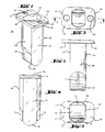
- the cuvette (11) shown in the accompanying figures is made of a translucent plastic, e.g. from a polymethyl methacrylate injection molding compound, molded in one piece. Due to the design described below, this cuvette is suitable for performing optical measurements of the cuvette contents.
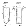
- the cuvette 11 has a tubular body 12, which has two plane-parallel walls 13, 14 and two side walls 27, 28, and which is open at one end 15 and closed by a bottom 16 at the opposite end.
- the light beam used runs through the plane-parallel walls 13, 14 and perpendicular to it.
- Each of the plane-parallel walls 13, 14 has at the open end 15 of the body a tongue 17, 18 which extends outwards from the edge of the open end 15 and which is directed perpendicular to the plane-parallel walls 13, 14.
- Each tongue 17, 18 has a cylindrical recess 21, 22 in its center.
- the tongues 17, 18 and their recesses 21, 22 are symmetrical to one another with respect to the longitudinal axis (Y-Y) of the cuvette 11.
- each of the depressions 21, 22 is preferably approximately half the dimension of the tongue 17 or 18 in the direction perpendicular to the plane-parallel walls 13, 14. This dimension is the width of the tongue measured between the edge of the open end 15 of the tubular body 12 of the cuvette and the outer edge of the tongue.
- each of the depressions 21, 22 is preferably approximately half the dimension of the tongue 17 or 18 in the direction parallel to the plane-parallel walls 13, 14. This dimension is the thickness of the tongue.
- Each tongue 17, 18 contains the area between the open end of its recess 21 or 22 and the outer edge 23 or 24 of the tongue preferably a flat surface 25, 26 which forms an angle of approximately 45 ° with a plane perpendicular to the longitudinal axis YY of the cuvette.
- the cuvette 11 Due to the design of the cuvette 11 described above, it is ideally suited for being gripped by a gripper-shaped gripper, not shown in the drawings, of a transport device, which is set up by means of a drive and a corresponding control unit to hold the cuvette at a predetermined removal position to grasp, carry them to a predetermined delivery position and deliver them there.
- the cuvette according to the invention is used to carry out spectrophotometric extinction measurements of a sample-reagent mixture contained therein, the light beam used for this runs through the lower part of the plane-parallel walls 13, 14, this lower part adjoining the base 16.
- the lower area of the plane-parallel walls 13, 14, which are used as optical measurement windows, must therefore meet corresponding optical requirements.
- the cuvette according to the invention should also be usable for carrying out fluorescence polarization measurements, and since such measurements measure light that leaves the cuvette through the base 16, the base of the cuvette must also meet corresponding optical requirements.
- the change in the direction of polarization which is caused by the optical windows involved (ie the portions of the plane-parallel walls 13, 14 and the base 16 involved) must be very small.
- the position of the sprue at the top edge of the cuvette is selected during the manufacture of the cuvette by injection molding, ie as far as possible from the lower part of the cuvette where the optical measurement windows are located.
- this choice causes a material confluence in the manufacturing process, which impairs the achievement of the desired properties of the optical measurement windows and also causes problems with ventilation during the injection molding.
- the tubular body 12 has two side walls 27, 28 which extend between the plane-parallel walls 13, 14, which side walls have an upper part and a lower part, the the lower part adjoins the bottom 16, and the lower part of each side wall 27, 28 includes an outer web 31, 32 which extends in the elongated direction of the cuvette between the upper part of the side wall to a point near the bottom 16.
- the webs 31, 32 each have an elongated, very fine gap, which serves as insert separation. This gap is not shown in the accompanying figures.
- the bottom 16 has the shape of a half cylinder.
- This base shape makes the cuvette particularly suitable for carrying out fluorescence polarization measurements because the calculations required for this are considerably simplified by the fact that the light beam used has a circular cross section and the base 16 is cylindrical.
Landscapes
- Chemical & Material Sciences (AREA)
- Health & Medical Sciences (AREA)
- General Health & Medical Sciences (AREA)
- Life Sciences & Earth Sciences (AREA)
- Analytical Chemistry (AREA)
- Biochemistry (AREA)
- Physics & Mathematics (AREA)
- General Physics & Mathematics (AREA)
- Immunology (AREA)
- Pathology (AREA)
- Clinical Laboratory Science (AREA)
- Chemical Kinetics & Catalysis (AREA)
- Optical Measuring Cells (AREA)
- Investigating, Analyzing Materials By Fluorescence Or Luminescence (AREA)
- Automatic Analysis And Handling Materials Therefor (AREA)
Claims (4)
- Cuvette (11) pour l'exécution de mesures optiques dans un appareil automatique d'analyse,
cette cuvettea) étant un élément formé en une pièce de matière plastique transparente,b) ayant un corps allongé (12) qui est ouvert à une extrémité (15) et fermé à l'extrémité opposée par un fond (16),c) ayant à l'extrémité ouverte (15) du corps deux languettes (17, 18) qui s'étendent à partir du bord de l'extrémité ouverte (15) vers l'extérieur, perpendiculairement à l'axe longitudinal de la cuvette, chaque languette ccmportant une cavité (21, 22), les languettes (17, 18) et leurs cavités (21, 22) étant mutuellement symétriques en référence à l'axe longitudinal (Y, Y) de la cuvette (11),caractérisée en ce qued) elle comprend un corps tubulaire (12) ayant deux parois planes et parallèles (13, 14) qui sont disposées entre l'extrémité ouverte (15) et le fond (16),e) les parois planes et parallèles (13, 14) sont disposées perpendiculairement aux languettes (17, 18),f) le fond (16) a la forme d'un demi-cylindre,g) le corps tubulaire (12) comprend deux parois latérales (27, 28) qui sont situées entre les parois planes et parallèles (13, 14), lesdites parois latérales ayant une partie supérieure et une partie inférieure, la partie inférieure avoisinant le fond (16) et la partie centrale inférieure de chaque paroi latérale (27, 28) comportant une nervure extérieure (31, 32) qui s'étend dans la direction de la longueur de la cuvette, entre la partie supérieure de la paroi latérale et un point situé à proximité du fond (16) eth) elle convient aussi bien à l'exécution de mesures d'extinction en photométrie spectrale qu'à l'exécution de mesures de polarisation par fluorescence. - Cuvette selon la revendication 1, caractérisée en ce que le diamètre de chaque cavité (21, 22) correspond à peu près à la moitié de la dimension de la languette (17, 18) en direction perpendiculaire aux parois planes et parallèles (13, 14).
- Cuvette selon la revendication 1, caractérisée en ce que la profondeur de chaque cavité (21, 22) correspond à peu près à la moitié de la dimension de la languette (17, 18) dans la direction parallèle aux parois planes et parallèles (13, 14).
- Cuvette selon la revendication 1, caractérisée en ce que la zone de chaque languette (17, 18) qui est comprise entre l'extrémité ouverte de sa cavité (21, 22) et le bord extérieur (23, 24) de la languette comprend une surface plane (25, 26) qui inscrit un angle d'environ 45° avec un plan perpendiculaire à l'axe longitudinal (Y-Y) de la cuvette.
Applications Claiming Priority (2)
| Application Number | Priority Date | Filing Date | Title |
|---|---|---|---|
| CH1368/91 | 1991-05-07 | ||
| CH136891 | 1991-05-07 |
Publications (3)
| Publication Number | Publication Date |
|---|---|
| EP0512368A2 EP0512368A2 (fr) | 1992-11-11 |
| EP0512368A3 EP0512368A3 (en) | 1993-02-03 |
| EP0512368B1 true EP0512368B1 (fr) | 1996-06-26 |
Family
ID=4208783
Family Applications (1)
| Application Number | Title | Priority Date | Filing Date |
|---|---|---|---|
| EP92107229A Expired - Lifetime EP0512368B1 (fr) | 1991-05-07 | 1992-04-28 | Cuvette pour mesurage optique |
Country Status (9)
| Country | Link |
|---|---|
| US (1) | US5437841A (fr) |
| EP (1) | EP0512368B1 (fr) |
| JP (2) | JPH05133881A (fr) |
| AU (1) | AU660016B2 (fr) |
| CA (1) | CA2067425C (fr) |
| DE (1) | DE59206639D1 (fr) |
| ES (1) | ES2089279T3 (fr) |
| NZ (1) | NZ242564A (fr) |
| SG (1) | SG43896A1 (fr) |
Cited By (2)
| Publication number | Priority date | Publication date | Assignee | Title |
|---|---|---|---|---|
| USD401700S (en) | 1997-05-22 | 1998-11-24 | Abbott Laboraties | Container for use with an automatic analyzer |
| US6562298B1 (en) | 1996-09-19 | 2003-05-13 | Abbott Laboratories | Structure for determination of item of interest in a sample |
Families Citing this family (34)
| Publication number | Priority date | Publication date | Assignee | Title |
|---|---|---|---|---|
| US5582184A (en) | 1993-10-13 | 1996-12-10 | Integ Incorporated | Interstitial fluid collection and constituent measurement |
| US5571479A (en) * | 1994-02-18 | 1996-11-05 | Hoffmann-La Roche Inc. | Cuvette |
| US5777303A (en) * | 1994-09-09 | 1998-07-07 | Gay Freres, Vente Et Exportation S.A. | Device for associating test tube samples with electronic labels for storage of identifying data |
| JP3251441B2 (ja) * | 1994-09-30 | 2002-01-28 | シスメックス株式会社 | キュベットおよびキュベット搬送装置 |
| US5589137A (en) * | 1995-04-07 | 1996-12-31 | Lab-Interlink, Inc. | Specimen carrier |
| US6614522B1 (en) * | 1995-09-08 | 2003-09-02 | Integ, Inc. | Body fluid sampler |
| US6624882B2 (en) | 1995-09-08 | 2003-09-23 | Integ, Inc. | Methods of sampling body fluid |
| US5682233A (en) * | 1995-09-08 | 1997-10-28 | Integ, Inc. | Interstitial fluid sampler |
| US5879310A (en) * | 1995-09-08 | 1999-03-09 | Integ, Inc. | Body fluid sampler |
| US5879367A (en) | 1995-09-08 | 1999-03-09 | Integ, Inc. | Enhanced interstitial fluid collection |
| US5795784A (en) | 1996-09-19 | 1998-08-18 | Abbott Laboratories | Method of performing a process for determining an item of interest in a sample |
| DE19826470C2 (de) | 1998-06-13 | 2001-10-18 | Eppendorf Ag | Küvettensystem und Küvette |
| USD457645S1 (en) | 1998-06-18 | 2002-05-21 | Gideon Eden | Transparent vial |
| US6368563B1 (en) | 1999-03-12 | 2002-04-09 | Integ, Inc. | Collection well for body fluid tester |
| GB0022013D0 (en) | 2000-09-07 | 2000-10-25 | Earth Canada Corp | Polyurethane oil de-emulsification unit |
| US6603544B1 (en) | 2002-02-06 | 2003-08-05 | Tech Ref, Inc. | Sample cell |
| US7138091B2 (en) * | 2003-07-18 | 2006-11-21 | Dade Behring Inc. | Reaction cuvette having anti-wicking features for use in an automatic clinical analyzer |
| US8211386B2 (en) | 2004-06-08 | 2012-07-03 | Biokit, S.A. | Tapered cuvette and method of collecting magnetic particles |
| US8343074B2 (en) * | 2004-06-30 | 2013-01-01 | Lifescan Scotland Limited | Fluid handling devices |
| WO2006086331A2 (fr) * | 2005-02-08 | 2006-08-17 | Cdex, Inc. | Cuve et coiffe pour cuve |
| USD655016S1 (en) * | 2009-02-05 | 2012-02-28 | Pocared Diagnostics, Ltd. | Optical cup |
| FR2957420A1 (fr) * | 2010-03-11 | 2011-09-16 | Stago Diagnostica | Tete de prehension d'une cuvette de reaction |
| USD706446S1 (en) | 2012-12-11 | 2014-06-03 | Pocared Diagnostics Ltd. | Optics cup with curved bottom |
| JP6208596B2 (ja) * | 2014-02-21 | 2017-10-04 | 株式会社日立ハイテクノロジーズ | 反応セル、及び生化学自動分析装置 |
| CN205246536U (zh) * | 2014-09-29 | 2016-05-18 | Bd科斯特公司 | 用于对样品光学探测的设备 |
| US9494510B2 (en) * | 2015-02-06 | 2016-11-15 | John L. Sternick | Cuvette system |
| USD808036S1 (en) | 2015-09-29 | 2018-01-16 | Bd Kiestra B.V. | Cuvette |
| USD810959S1 (en) | 2015-09-29 | 2018-02-20 | Bd Kiestra B.V. | Cuvette tray |
| CN105891114B (zh) * | 2016-05-25 | 2019-03-29 | 广西科技大学 | 用于测量散射光谱的比色皿及其光学系统 |
| USD855826S1 (en) | 2017-07-10 | 2019-08-06 | Gen-Probe Incorporated | Receptacle holder |
| WO2019206278A1 (fr) * | 2018-04-28 | 2019-10-31 | 东莞德益生物医疗科技有限公司 | Récipient de réaction pour test |
| US20230228671A1 (en) * | 2019-10-15 | 2023-07-20 | Yep Co.,Ltd. | Rectangular cell for photometric analysis |
| US12546703B2 (en) * | 2023-03-13 | 2026-02-10 | Intersurgical Ag | Paediatric cuvette |
| WO2025158805A1 (fr) * | 2024-01-23 | 2025-07-31 | 株式会社日立ハイテク | Dispositif d'analyse automatique et récipient |
Family Cites Families (22)
| Publication number | Priority date | Publication date | Assignee | Title |
|---|---|---|---|---|
| DE1773584A1 (de) * | 1967-06-13 | 1973-01-04 | Xerox Corp | Reaktionsbehaelter |
| CH493834A (de) * | 1968-05-02 | 1970-07-15 | Eppendorf Geraetebau Netheler | Reaktionsgefäss aus Kunststoff zur fotometrischen Untersuchung kleiner Flüssigkeitsmengen |
| FR2036769A1 (fr) * | 1969-03-26 | 1970-12-31 | Dassault Electronique | |
| SE385988B (sv) * | 1973-06-21 | 1976-07-26 | Platmanufaktur Ab | Identifieringsanordning for formnummerlesning pa maskinformade produkter exv. plast- eller glasprodukter |
| US4024857A (en) * | 1974-12-23 | 1977-05-24 | Becton, Dickinson And Company | Micro blood collection device |
| US3994594A (en) * | 1975-08-27 | 1976-11-30 | Technicon Instruments Corporation | Cuvette and method of use |
| US4043678A (en) * | 1976-03-01 | 1977-08-23 | Technicon Instruments Corporation | Cuvette |
| US4119407A (en) * | 1976-03-08 | 1978-10-10 | Bio-Dynamics, Inc. | Cuvette with reagent release means |
| JPS5536807A (en) * | 1978-09-07 | 1980-03-14 | Tdk Electronics Co Ltd | Power supplyyfree type rechargeable display |
| JPS55136958A (en) * | 1979-04-14 | 1980-10-25 | Olympus Optical Co Ltd | Automatic analyzer |
| DE2922697A1 (de) * | 1979-06-02 | 1980-12-11 | Hoechst Ag | Kuevette fuer optische untersuchungen von fluessigkeiten |
| US4263256A (en) * | 1979-11-05 | 1981-04-21 | Coulter Electronics, Inc. | Cuvettes for automatic chemical apparatus |
| AT382971B (de) * | 1981-06-16 | 1987-05-11 | Hoffmann La Roche | Verfahren und vorrichtung zur messung der blutgerinnungszeit |
| US4371498A (en) * | 1981-06-19 | 1983-02-01 | Medical Laboratory Automation, Inc. | Coded cuvette for use in testing apparatus |
| NL8105341A (nl) * | 1981-11-26 | 1983-06-16 | Akzo Nv | Diagnostische test methode. |
| US4799599A (en) * | 1982-07-30 | 1989-01-24 | Ciba Corning Diagnostics Corp. | Specimen cup and cap assembly for clinical analyzer |
| JPS58131540A (ja) * | 1982-10-05 | 1983-08-05 | Olympus Optical Co Ltd | 化学分析用キユベツト |
| FI81913C (fi) * | 1984-02-23 | 1990-12-10 | Hoffmann La Roche | Skaolanordning. |
| JPS6342350U (fr) * | 1986-09-06 | 1988-03-19 | ||
| JPH051280Y2 (fr) * | 1987-10-12 | 1993-01-13 | ||
| US5098661A (en) * | 1988-11-16 | 1992-03-24 | Medical Laboratory Automation, Inc. | Coded cuvette for use in testing apparatus |
| JPH0394141A (ja) * | 1989-09-06 | 1991-04-18 | Hitachi Ltd | 反応セル構造体 |
-
1992
- 1992-04-28 ES ES92107229T patent/ES2089279T3/es not_active Expired - Lifetime
- 1992-04-28 SG SG1996004368A patent/SG43896A1/en unknown
- 1992-04-28 EP EP92107229A patent/EP0512368B1/fr not_active Expired - Lifetime
- 1992-04-28 DE DE59206639T patent/DE59206639D1/de not_active Expired - Lifetime
- 1992-04-28 CA CA002067425A patent/CA2067425C/fr not_active Expired - Fee Related
- 1992-04-30 NZ NZ242564A patent/NZ242564A/en not_active IP Right Cessation
- 1992-05-04 AU AU16006/92A patent/AU660016B2/en not_active Ceased
- 1992-05-07 JP JP4114942A patent/JPH05133881A/ja active Pending
-
1994
- 1994-01-21 US US08/184,521 patent/US5437841A/en not_active Expired - Lifetime
-
1996
- 1996-01-12 JP JP1996000046U patent/JP2539722Y2/ja not_active Expired - Lifetime
Cited By (2)
| Publication number | Priority date | Publication date | Assignee | Title |
|---|---|---|---|---|
| US6562298B1 (en) | 1996-09-19 | 2003-05-13 | Abbott Laboratories | Structure for determination of item of interest in a sample |
| USD401700S (en) | 1997-05-22 | 1998-11-24 | Abbott Laboraties | Container for use with an automatic analyzer |
Also Published As
| Publication number | Publication date |
|---|---|
| JPH05133881A (ja) | 1993-05-28 |
| CA2067425C (fr) | 1996-09-24 |
| JPH081384U (ja) | 1996-09-13 |
| EP0512368A2 (fr) | 1992-11-11 |
| JP2539722Y2 (ja) | 1997-06-25 |
| ES2089279T3 (es) | 1996-10-01 |
| AU1600692A (en) | 1992-11-12 |
| DE59206639D1 (de) | 1996-08-01 |
| AU660016B2 (en) | 1995-06-08 |
| NZ242564A (en) | 1994-02-25 |
| SG43896A1 (en) | 1997-11-14 |
| US5437841A (en) | 1995-08-01 |
| EP0512368A3 (en) | 1993-02-03 |
| CA2067425A1 (fr) | 1992-11-08 |
Similar Documents
| Publication | Publication Date | Title |
|---|---|---|
| EP0512368A2 (fr) | Cuvette pour mesurage optique | |
| EP0668496B1 (fr) | Cuvette pour mesurage optique | |
| DE3005508C2 (fr) | ||
| DE69312863T2 (de) | Küvetten Matrix | |
| DE2641097C2 (de) | Küvette zum Durchführen von optischen Analysen und ihre Verwendung für die Hämoglobinbestimmung | |
| DE3836163C2 (fr) | ||
| DE60213873T2 (de) | Stapelbare probengefässanordnung | |
| DE3537734C2 (de) | Vorrichtung für eine immunochemische Agglutinationsreaktion flüssiger Partikelreagenzien | |
| EP0618443B1 (fr) | Analyseur pour bandes de test | |
| DE69828743T2 (de) | Gerät zum automatischen lesen eines identifikationscodes auf rohrförmigen behältern | |
| EP0152964A2 (fr) | Agencement de cuvettes | |
| DE2302448C3 (de) | Probenzelle mit Rührwerk, insbesondere für spektral-photometrische Geräte | |
| DE19826470A1 (de) | Küvette | |
| EP0019871B1 (fr) | Cuvette pour l'examen optique de fluides | |
| DE69413643T2 (de) | Probentraeger | |
| DD239473A1 (de) | Probentraeger zur diskreten analyse fluessiger analysensaetze | |
| WO1995009352A1 (fr) | Cassette de traitement d'echantillons en vue d'examens histologiques, notamment de preparation de coupes | |
| DE19857215B4 (de) | Multiküvettenrotor | |
| DE4016617A1 (de) | Objekttraeger fuer nasse oder feuchte praeparate, z. b. blut | |
| DE102013215210B3 (de) | Reaktionsgefäß, Reaktionsgefäßanordnung und Verfahren zur Analyseeiner Substanz | |
| DE2905234A1 (de) | Probenzelle und ruehrer fuer spektrophotometrie | |
| DE1299136B (de) | Kuevette mit Temperiermantel, insbesondere solche Fluessigkeitskuevette | |
| DE19512430A1 (de) | Mikrotiterplatte | |
| EP0896662B1 (fr) | Barre a cuvettes | |
| DE69113614T2 (de) | Navigationshilfe mit halter für transparente karten. |
Legal Events
| Date | Code | Title | Description |
|---|---|---|---|
| PUAI | Public reference made under article 153(3) epc to a published international application that has entered the european phase |
Free format text: ORIGINAL CODE: 0009012 |
|
| 17P | Request for examination filed |
Effective date: 19920429 |
|
| AK | Designated contracting states |
Kind code of ref document: A2 Designated state(s): BE CH DE ES FR GB IT LI NL |
|
| PUAL | Search report despatched |
Free format text: ORIGINAL CODE: 0009013 |
|
| AK | Designated contracting states |
Kind code of ref document: A3 Designated state(s): BE CH DE ES FR GB IT LI NL |
|
| 17Q | First examination report despatched |
Effective date: 19930728 |
|
| GRAH | Despatch of communication of intention to grant a patent |
Free format text: ORIGINAL CODE: EPIDOS IGRA |
|
| GRAA | (expected) grant |
Free format text: ORIGINAL CODE: 0009210 |
|
| ITF | It: translation for a ep patent filed | ||
| AK | Designated contracting states |
Kind code of ref document: B1 Designated state(s): BE CH DE ES FR GB IT LI NL |
|
| REF | Corresponds to: |
Ref document number: 59206639 Country of ref document: DE Date of ref document: 19960801 |
|
| ET | Fr: translation filed | ||
| REG | Reference to a national code |
Ref country code: ES Ref legal event code: FG2A Ref document number: 2089279 Country of ref document: ES Kind code of ref document: T3 |
|
| GBT | Gb: translation of ep patent filed (gb section 77(6)(a)/1977) |
Effective date: 19960926 |
|
| REG | Reference to a national code |
Ref country code: ES Ref legal event code: FG2A Ref document number: 2089279 Country of ref document: ES Kind code of ref document: T3 |
|
| PLBE | No opposition filed within time limit |
Free format text: ORIGINAL CODE: 0009261 |
|
| STAA | Information on the status of an ep patent application or granted ep patent |
Free format text: STATUS: NO OPPOSITION FILED WITHIN TIME LIMIT |
|
| 26N | No opposition filed | ||
| REG | Reference to a national code |
Ref country code: GB Ref legal event code: IF02 |
|
| PGFP | Annual fee paid to national office [announced via postgrant information from national office to epo] |
Ref country code: BE Payment date: 20080507 Year of fee payment: 17 |
|
| PGFP | Annual fee paid to national office [announced via postgrant information from national office to epo] |
Ref country code: NL Payment date: 20080325 Year of fee payment: 17 |
|
| PGFP | Annual fee paid to national office [announced via postgrant information from national office to epo] |
Ref country code: GB Payment date: 20090312 Year of fee payment: 18 |
|
| PGFP | Annual fee paid to national office [announced via postgrant information from national office to epo] |
Ref country code: CH Payment date: 20090430 Year of fee payment: 18 |
|
| BERE | Be: lapsed |
Owner name: F. *HOFFMANN-LA ROCHE A.G. Effective date: 20090430 |
|
| NLV4 | Nl: lapsed or anulled due to non-payment of the annual fee |
Effective date: 20091101 |
|
| PG25 | Lapsed in a contracting state [announced via postgrant information from national office to epo] |
Ref country code: NL Free format text: LAPSE BECAUSE OF NON-PAYMENT OF DUE FEES Effective date: 20091101 |
|
| PG25 | Lapsed in a contracting state [announced via postgrant information from national office to epo] |
Ref country code: BE Free format text: LAPSE BECAUSE OF NON-PAYMENT OF DUE FEES Effective date: 20090430 |
|
| REG | Reference to a national code |
Ref country code: CH Ref legal event code: PL |
|
| GBPC | Gb: european patent ceased through non-payment of renewal fee |
Effective date: 20100428 |
|
| PG25 | Lapsed in a contracting state [announced via postgrant information from national office to epo] |
Ref country code: LI Free format text: LAPSE BECAUSE OF NON-PAYMENT OF DUE FEES Effective date: 20100430 Ref country code: CH Free format text: LAPSE BECAUSE OF NON-PAYMENT OF DUE FEES Effective date: 20100430 |
|
| PG25 | Lapsed in a contracting state [announced via postgrant information from national office to epo] |
Ref country code: GB Free format text: LAPSE BECAUSE OF NON-PAYMENT OF DUE FEES Effective date: 20100428 |
|
| PGFP | Annual fee paid to national office [announced via postgrant information from national office to epo] |
Ref country code: FR Payment date: 20110331 Year of fee payment: 20 |
|
| PGFP | Annual fee paid to national office [announced via postgrant information from national office to epo] |
Ref country code: ES Payment date: 20110414 Year of fee payment: 20 Ref country code: DE Payment date: 20110429 Year of fee payment: 20 |
|
| PGFP | Annual fee paid to national office [announced via postgrant information from national office to epo] |
Ref country code: IT Payment date: 20110423 Year of fee payment: 20 |
|
| REG | Reference to a national code |
Ref country code: DE Ref legal event code: R071 Ref document number: 59206639 Country of ref document: DE |
|
| REG | Reference to a national code |
Ref country code: DE Ref legal event code: R071 Ref document number: 59206639 Country of ref document: DE |
|
| REG | Reference to a national code |
Ref country code: ES Ref legal event code: FD2A Effective date: 20120717 |
|
| PG25 | Lapsed in a contracting state [announced via postgrant information from national office to epo] |
Ref country code: DE Free format text: LAPSE BECAUSE OF EXPIRATION OF PROTECTION Effective date: 20120429 Ref country code: ES Free format text: LAPSE BECAUSE OF EXPIRATION OF PROTECTION Effective date: 20120429 |