EP0512444B1 - Verfahren zur Herstellung eines Blasformkörpers - Google Patents
Verfahren zur Herstellung eines Blasformkörpers Download PDFInfo
- Publication number
- EP0512444B1 EP0512444B1 EP92107476A EP92107476A EP0512444B1 EP 0512444 B1 EP0512444 B1 EP 0512444B1 EP 92107476 A EP92107476 A EP 92107476A EP 92107476 A EP92107476 A EP 92107476A EP 0512444 B1 EP0512444 B1 EP 0512444B1
- Authority
- EP
- European Patent Office
- Prior art keywords
- blow
- moulded body
- foam
- moulded article
- blowing mould
- Prior art date
- Legal status (The legal status is an assumption and is not a legal conclusion. Google has not performed a legal analysis and makes no representation as to the accuracy of the status listed.)
- Expired - Lifetime
Links
Images
Classifications
-
- B—PERFORMING OPERATIONS; TRANSPORTING
- B29—WORKING OF PLASTICS; WORKING OF SUBSTANCES IN A PLASTIC STATE IN GENERAL
- B29C—SHAPING OR JOINING OF PLASTICS; SHAPING OF MATERIAL IN A PLASTIC STATE, NOT OTHERWISE PROVIDED FOR; AFTER-TREATMENT OF THE SHAPED PRODUCTS, e.g. REPAIRING
- B29C44/00—Shaping by internal pressure generated in the material, e.g. swelling or foaming ; Producing porous or cellular expanded plastics articles
- B29C44/02—Shaping by internal pressure generated in the material, e.g. swelling or foaming ; Producing porous or cellular expanded plastics articles for articles of definite length, i.e. discrete articles
- B29C44/12—Incorporating or moulding on preformed parts, e.g. inserts or reinforcements
- B29C44/14—Incorporating or moulding on preformed parts, e.g. inserts or reinforcements the preformed part being a lining
- B29C44/146—Shaping the lining before foaming
-
- B—PERFORMING OPERATIONS; TRANSPORTING
- B29—WORKING OF PLASTICS; WORKING OF SUBSTANCES IN A PLASTIC STATE IN GENERAL
- B29C—SHAPING OR JOINING OF PLASTICS; SHAPING OF MATERIAL IN A PLASTIC STATE, NOT OTHERWISE PROVIDED FOR; AFTER-TREATMENT OF THE SHAPED PRODUCTS, e.g. REPAIRING
- B29C49/00—Blow-moulding, i.e. blowing a preform or parison to a desired shape within a mould; Apparatus therefor
- B29C49/02—Combined blow-moulding and manufacture of the preform or the parison
- B29C49/04—Extrusion blow-moulding
-
- B—PERFORMING OPERATIONS; TRANSPORTING
- B29—WORKING OF PLASTICS; WORKING OF SUBSTANCES IN A PLASTIC STATE IN GENERAL
- B29K—INDEXING SCHEME ASSOCIATED WITH SUBCLASSES B29B, B29C OR B29D, RELATING TO MOULDING MATERIALS OR TO MATERIALS FOR MOULDS, REINFORCEMENTS, FILLERS OR PREFORMED PARTS, e.g. INSERTS
- B29K2105/00—Condition, form or state of moulded material or of the material to be shaped
- B29K2105/04—Condition, form or state of moulded material or of the material to be shaped cellular or porous
-
- B—PERFORMING OPERATIONS; TRANSPORTING
- B29—WORKING OF PLASTICS; WORKING OF SUBSTANCES IN A PLASTIC STATE IN GENERAL
- B29K—INDEXING SCHEME ASSOCIATED WITH SUBCLASSES B29B, B29C OR B29D, RELATING TO MOULDING MATERIALS OR TO MATERIALS FOR MOULDS, REINFORCEMENTS, FILLERS OR PREFORMED PARTS, e.g. INSERTS
- B29K2105/00—Condition, form or state of moulded material or of the material to be shaped
- B29K2105/04—Condition, form or state of moulded material or of the material to be shaped cellular or porous
- B29K2105/043—Skinned foam
Definitions
- the invention relates to a method for producing a blow molded body by means of the extrusion blow molding process using a split blow mold, the preformiling being introduced as a tubular semi-finished product in the thermoplastic material state into the opened blow mold, after it being closed, applied to the inner contours of the blow mold by a defined blow pressure and after the stabilization is taken as a finished blow molding from the reopened blow mold, the hollow interior of the blow molding being filled with a foam mass between the end of the inflation process and the opening of the blow mold.
- hollow bodies of any shape can be produced.
- foam a method for foaming elongated hollow bodies is known, in which a solid foam precursor in the form of a rod of suitable cross-section is inserted lengthways into the cavity and the volume is increased by foaming either gets started by the passage of time or is started by suitable measures, for example heat supply.
- the first process step is the production of the blow mold parts, which ends when these moldings are removed from the open blow mold.
- the second process step concerns the filling of these blow molded parts with foam.
- the finished blow-molded part has to be placed in a support mold during foaming for reasons of stability, which is tempered due to the process. After the foam has been introduced and a stabilization period has expired, the blow-molded part which has been foamed out can then be removed from the support mold.
- a method for producing a hermetically sealed container by blow molding which has a sterile inner discharge outlet.
- This container is made by extruding a relatively warm plastic preform, which preform is held between two movable mold halves.
- These movable tool halves have inner surfaces that define the shape of the container and at least part of the container neck.
- a mandrel is lowered into the tubular preform and the container is blow molded, the sterile medical fluid being introduced through the mandrel into the interior of the blow molded container prior to opening the tool halves.
- the filling mandrel is withdrawn after the container has been filled with the medical liquid, and the container is closed by a closure piece pressed into the neck of the container to form a liquid-tight connection.
- DE-A 1 629 543 discloses a process for producing a blow molded body by an extrusion blow molding process using a split blow mold, the preform being introduced as a tube in the plastic material state into the opened blow mold, after it has been closed by a defined blowing pressure on the inner contours of the blow mold created and then the inner cavity is filled with foam using the process heat remaining in the molded body wall.
- the object of the invention is to avoid the disadvantages described in relation to the prior art and to provide a method for improving the mechanical or thermal properties of blow-molded hollow bodies which can be carried out simply and inexpensively. According to the invention it is proposed that preformed foam particles are used to fill the blown body.
- the invention takes advantage of the fact that, in the extrusion blow molding process, the molded blow part with its inner cavity lies completely against the contour of the blow molding tool with its outer contours before removal from the split blow mold.
- the wall of the blow part in this phase has a temperature between approx. 100 ° and 180 ° C depending on the material processed.
- the preformed foam particles introduced according to the invention form a firm connection when the inner wall of the blow molded body contacts the latter.
- the remaining process heat of the blow molding wall should be a maximum of 120 °. Temperatures in excess of this could damage the foam particles. Vesuche have shown that up to the specified maximum temperature of 120 ° C EPS or PP particle foam have given optimal results.
- the inventive blow molding is filled under an internal pressure of 2-8 bar required to stabilize the blow part.
- the filling pressure with which the particle foam is pressed into the interior of the blow molded body must therefore exceed this stabilizing pressure.
- the foam particles that are not directly connected to the molded body wall can be separated by additional when using particle foam Blowing in a moist fluid in the form of a sintering process can be connected to one another, the process heat still present in the container wall also being used here.
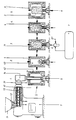
- the drawing shows the schematic sequence of the method according to the invention for producing a blow molded article.
- An extruder 1 with a feed hopper 11 for the polymeric material 12 from which the blow molding body wall 3 is formed is shown.
- the polymeric material 12 is drawn into the conveying path of an extrusion screw 13, plasticized there and discharged via the tool 14 as a tubular semifinished product 31.
- the tubular semifinished product 31 is inserted into the split blow mold 4 with the blow mold halves 41, 42. As soon as the semifinished product 31 has reached over the blow mandrel 5 at its tip, the blow mold halves 41, 42 are closed and the blow mold 4 is removed from the extruder 1. Blowing air is introduced immediately afterwards into the interior of the semifinished product 31 and the preform is placed against the inner contours of the blow mold 4.
- the blow mandrel is decoupled from the compressed air source and connected to a delivery injector 6, which is connected to a silo 7 filled with pre-expanded particle foam.
- the delivery injector 6 is connected to an air source 61 for entering the delivery air.
- the particle foam 71 is conveyed from the silo 7 into the hollow interior 43 of the blow molded body via the delivery injector 6.
- the blow mold 4 is then uncoupled from the delivery injector 6 and cooled in a stabilization phase in preparation for the removal of the filled blow molded body. If necessary, the foam particles can be sintered together by blowing in moist air before the final cooling.
- blow mold halves 41, 42 are opened again and the finished blow molded body 8 filled with particle foam can be pulled off the blow mandrel 5 and removed from the mold.
- the hollow interior of the blow molded body is filled in the schematic sketch and its description via the blow mandrel 5. This filling form is useful when the blow molded body has a larger volume. Small-volume blow molded articles, but also those with a larger volume, can be filled according to the invention using known injection devices.
Landscapes
- Engineering & Computer Science (AREA)
- Manufacturing & Machinery (AREA)
- Mechanical Engineering (AREA)
- Blow-Moulding Or Thermoforming Of Plastics Or The Like (AREA)
- Dental Preparations (AREA)
- Materials For Medical Uses (AREA)
- Casting Or Compression Moulding Of Plastics Or The Like (AREA)
- Air Bags (AREA)
- Ultra Sonic Daignosis Equipment (AREA)
- Moulds For Moulding Plastics Or The Like (AREA)
Description
- Die Erfindung betrifft ein Verfahren zur Herstellung eines Blasformkörpers im Wege des Extrusionsblasverfahrens unter Verwendung einer geteilten Blasform, wobei der Vorformiling als schlauchförmiges Halbzeug in thermoplastischem Materialzustand in die geöffnete Blasform eingebracht, nach deren Schließen durch einen definierten Blasdruck an die inneren Konturen der Blasform angelegt und nach dem Stabilisieren als fertiger Blasformkörper aus der wiedergeöffneten Blasform entnommen wird, wobei zwischen dem Ende des Aufblasvorgangs und dem Öffnen der Blasform der hohle Innenraum des Blasformkörpers mit einer Schaummasse gefüllt wird.
- Derlei Verfahren zur Herstellung von Blasformkörpern sind in vielerlei Hinsicht bekannt. Als Beispiel soll die DE-OS 25 56 186 dienen. Aus dieser Schrift ist ein Spritzblasverfahren zur Herstellung von Hohlkörpern aus thermoplastischem Kunststoff bekannt, bei dem in nacheinanderfolgenden Verfahrensschritten ein Hohlstrang aus thermoplastischem Kunststoff extrudiert und das Ende des Hohlstranges druckdicht verschlossen wird. Der in dem abgeschlossenen Hohlstrangabschnitt eingeschlossene Hohlraum wird durch Einleiten eines Druckgases innerhalb einer Hohlform aufgeblasen, bis der Hohlstrang an der Formwandung anliegt. Nach dem Erkalten wird der fertige Formkörper aus der dann geöffneten Form entnommen.
- Mit solchen Verfahren nach dem Stand der Technik lassen sich beliebig geformte Hohlkörper herstellen. Zur Verbesserung der mechanischen oder thermischen Eigenschaften solcher Hohlkörper ist es bekannt, die Hohlkörper ganz oder teilweise mit Schaum zu füllen. Verwiesen wird hierzu auf die DE-OS 21 06 633. Aus dieser Schrift ist ein Verfahren zum Ausschäumen länglicher Hohlkörper bekannt, bei dem ein festes Schaumvorprodukt in Form eines Stabes von geeignetem Querschnitt der Länge nach in den Hohlraum eingeschoben wird und hierauf die Volumenvergrößerung durch Aufschäumen entweder durch Zeitablauf in Gang kommt oder durch geeignete Maßnahmen, beispielsweise Wärmezufuhr, in Gang gesetzt wird.
- Im beschreibenden Teil dieser Vorveröffentlichung wird darauf hingewiesen, daß es ferner bereits bekannt war, geschlossene Hohlprofile dadurch auszuschäumen, daß ein zähflüssiger Schaumansatz in das Innere der geschlossenen Hohlprofile gebracht und dort ausgeschäumt wird. Dabei hat sich allerdings die kurze, bis zum Beginn des Aufschäumens zur Verfügung stehende Zeit als nachteilig herausgestellt. Nach den Angaben in dieser Vorveröffentlichung behilft man sich mit Sonden, welche entweder nur einen Teilbereich der geschlossenen Hohlprofile bestreichen oder welche mit einer Reihe von über den Hohlraum verteilten Bohrungen versehen sind, durch welche der zähflüssige Schaumansatz in einzelnen Portionen in den Hohlraum eingefüllt wird.
- Allen bekannten Verfahren zum Ausschäumen geschlossener Hohlprofile ist der Nachteil zu eigen, daß aus prozesstechnischen Gründen zwei getrennte Verfahrensschritte unternommen werden müssen. Der erste Verfahrensschritt ist das Herstellen der Blasformteile, das mit dem Entnehmen dieser Formkörper aus der geöffneten Blasform endet.
- Der zweite Verfahrensschritt betrifft das Füllen dieser Blasformteile mit Schaum. Dabei muß in der Regel das fertige Blasformteil beim Ausschäumen aus Stabilitätsgründen in eine Stützform eingelegt werden, welche verfahrensbedingt temperiert ist. Nach dem Einbringen des Schaumes und dem Ablauf einer Stabilisierungszeit kann das fertig ausgeschäumte Blasformteil dann der Stützform entnommen werden.
- Aus der DE-OS 34 45 542 ist ein Verfahren zur Herstellung eines hermetisch dichten Behälters durch Blasformung bekannt, der einen sterilen inneren Abgabeauslaß aufweist. Dieser Behälter wird durch Extrudieren eines relativ warmen Kunststoff-Vorformlings hergestellt, wobei dieser Vorformling zwischen zwei beweglichen Werkzeughälften gehalten wird. Diese beweglichen Werkzeughälften weisen Innenflächen auf, die die Form des Behälters und wenigstens einen Teil des Behälterhalses definieren.
- Nach dem Schließen der Werkzeughälften wird ein Fülldorn in den rohrförmigen Vorformling abgesenkt und der Behälter blasgeformt, wobei die sterile medizinische Flüssigkeit durch den Fülldorn in das Innere des blasgeformten Behälters vor dem Öffnen der Werkzeughälften eingebracht wird. Der Fülldorn wird nach dem Befüllen des Behälters mit der medizinischen Flüssigkeit zurückgezogen und der Behälter wird durch ein in den Behälterhals gepresstes Verschlußstück unter Bildung einer flüssigkeitsdichten Verbindung geschlossen.
- Es handelt sich hier um ein kompliziertes und teures Verfahren, bei dem ein im Blasformverfahren hergestellter Behälter noch in der Form mit medizinischen Flüssigkeiten gefüllt und anschließend sofort steril verschlossen wird. Aus medizinischen Gründen müssen die Kosten solcher Verfahren akzeptiert werden; bei technischen Behältern sind solche Aufwendungen jedoch nicht zu tolerieren.
- Die DE-A 1 629 543 offenbart ein Verfahren zur Herstellung eines Blasformkörpers durch ein Extrusionsblasverfahren unter Verwendung einer geteilten Blasform, wobei der Vorformling als Schlauch im plastischen Materialzustand in die geöffnete Blasform eingebracht, nach deren Schließen durch einen definierten Blasdruck an die inneren Konturen der Blasform angelegt und danach der innere Hohlraum unter Ausnutzung der in der Formkörperwand verbliebenen Prozeßwärme mit Schaumstoff ausgefüllt wird.
- Das Befüllen bei dieser Vorveröffentlichung erfolgt allerdings mit einer schäumfähigen Mischung, welche in den Hohlraum der Blasformkörpers vor dem Öffnen der Blasform eingespritzt wird. Darüberhinaus kann eine mit einem gasförmigen Treibmittel versehene schäumfähige thermoplastifizierte Kunststoffmasse verwendet werden.
- Sowohl bei der Zweikomponenten-Schäumung als auch bei der Ausschäumung mittels Treibgas ist ein hoher apparativer Aufwand erforderlich. Dieser apparative Aufwand mag bei den Gegenständen, die mit diesem Verfahren erzeugt werden, gerechtfertigt sein, da Formteile mit einer sehr dünnen Außenhaut hergestellt werden sollen. Unter diesen erschwerten Umständen muß eine vollkommene Ausfüllung der Hülle durch den Schaumstoff erfolgen, wobei die zu erzeugende Schaummenge durch die eingesetzten Anteile der Polyurethanschaumkomponenten Polyol und Isocyanat einerseits sowie durch die genaue Einstellung des Schußgewichts bei der Verwendung von gasfähigen Treibmitteln in der Spritzgußmaschine andererseits exakt eingestellt werden können.
- Die Erfindung hat sich die Aufgabe gestellt, die zum Stand der Technik geschilderten Nachteile zu vermeiden und ein Verfahren zur mechanischen oder thermischen Eigenschaftsverbesserung von blasgeformten Hohlkörpern anzugeben, das sich einfach und kostengünstig durchführen läßt. Erfindungsgemäß wird dazu vorgeschlagen, daß zur Füllung des Blaskörpers vorgeformte Schaumstoffpartikel verwendet werden.
- Die Erfindung macht sich den Vorteil zunutze, daß beim Extrusionsblasverfahren das ausgeformte Blasteil mit seinem inneren Hohlraum vor der Entnahme aus der geteilten Blasform mit seinen Außenkonturen in vollem Umfang an der Kontur des Blasformwerkzeuges anliegt. Prozessbedingt besitzt die Wandung des Blasteils in dieser Phase je nach verarbeitetem Material eine Temperatur zwischen ca. 100° und 180° C.
- Während beim herkömmlichen Extrusionsblasverfahren nach diesen Prozeßschritten anschließend die Phase des Stabilisierens und Kühlens sowie der Entnahme des Blasformkörpers aus dem geöffneten Werkzeug erfolgt, werden in dieser Phase für das erfindungsgemäße Verfahren zwei wesentliche Bedingungen für das Befüllen des Hohlraumes des Blasformkörpers mit Schaumpartikeln geboten:
- 1. Das noch geschlossene Blaswerkzeug wirkt als Stützwerkzeug gegen den Einfülldruck.
- 2. Der Blasformkörper ist verfahrensbedingt in dieser Situation temperiert.
- Es entfällt also das beim Stand der Technik beim nachträglichen Befüllen mit Schaumpartikeln erforderliche Stützwerkzeug sowie das dafür erforderliche erneute Temperieren des Blasformteils.
- Die erfindungsgemäß eingebrachten vorgeformten Schaumstoffpartikeln gehen bei der Berührung der Innenwand des Blasformkörpers mit dieser eine feste Verbindung ein.
- Bei der Befüllung des Hohlraumes mit Schaumstoffpartikeln sollte die restliche Prozesswärme der Blasformkörperwand maximal 120° betragen. Darüber hinausgehende Temperaturen könnten die Schaumstoffpartikel beschädigen. Vesuche haben gezeigt, daß bis zu der angegebenen Maximaltemperatur von 120°C EPS- oder PP-Partikelschaum optimale Ergebnisse gebracht haben.
- Das erfindungsgemäße Befüllen des Blasformkörpers erfolgt unter einem zur Stabilisierung des Blasteils erforderlichen Innendruck von 2-8 bar. Der Fülldruck, mit dem der Partikelschaum in den Innenraum des Blasformkörpers eingedrückt werden, muß also diesen Stabilisierungsdruck übersteigen.
- Die besonderen Vorteile des erfindungsgemäßen Verfahrens werden damit verdeutlicht, daß bei der Verwendung von Partikelschaum die Füllung des Blasformkörpers nach einer kurzen Stabilisierungsphase, die je nach Wanddicke der Blasformkörpers zwischen 0,5 und 3 Minuten beträgt, das gefüllte Blasteil aus der dann geöffneten Form entnommen werden kann.
- Die nicht mit der Formkörperwand direkt verbundenen Schaumstoffpartikel können bei der Verwendung von Partikelschaum durch zusätzliches Einblasen eines feuchten Fluids in Form eines Sinterprozesses miteinander verbunden werden, wobei auch hier die in der Behälterwand noch vorhandene Prozesswärme ausgenutzt wird.
- In der Zeichnung ist der schematische Ablauf des erfindungsgemäßen Verfahrens zur Herstellung eines Blasformkörpers dargestellt. Gezeigt ist ein Extruder 1 mit Einfülltrichter 11 für das polymere Material 12 aus dem die Blasformkörperwand 3 gebildet ist. Das polymere Material 12 wird in den Fördergang einer Extrusionsschnecke 13 eingezogen, dort plastifiziert und über das Werkzeug 14 als schlauchförmiges Halbzeug 31 ausgetragen.
- Das schlauchförmige Halbzeug 31 wird in die geteilte Blasform 4 mit den Blasformhälften 41, 42 eingefahren. Sobald das Halbzeug 31 den Blasdorn 5 an dessen Spitze übergriffen hat, werden die Blasformhälften 41, 42 geschlossen und die Blasform 4 vom Extruder 1 entfernt. Es erfolgt unmittelbar anschließend die Einführung von Blasluft in das Innere des Halbzeugs 31 und das Anlegen des Vorformlings an die inneren Konturen der Blasform 4.
- Im nächsten Verfahrensschritt wird der Blasdorn von der Druckluftquelle abgekoppelt und an einen Förderinjektor 6 angeschlossen, der mit einem mit vorgeschäumten Partikelschaum gefüllten Silo 7 verbunden ist. Der Förderinjektor 6 ist mit einer Luftquelle 61 für das Eintragen der Förderluft verbunden. Über den Förderinjektor 6 wird der Partikelschaum 71 aus dem Silo 7 in den hohlen Innenraum 43 des Blasformkörpers gefördert.
- Danach wird die Blasform 4 vom Förderinjektor 6 abgekoppelt und in einer Stabilisierungsphase zur Vorbereitung der Entnahme des gefüllten Blasformkörpers abgekühlt. Vor der endgültigen Abkühlung kann im Bedarfsfall das Versintern der Schaumstoffpartikel untereinander mittels Einblasen von feuchter Luft erfolgen.
- In der letzten Schemaskizze sind die Blasformhälften 41, 42 wieder geöffnet und der fertige, mit Partikelschaum gefüllte Blasformkörper 8 kann vom Blasdorn 5 abgezogen und aus der Form entnommen werden.
- Die Befüllung des hohlen Innenraums des Blasformkörpers erfolgt bei der Schemaskizze und deren Beschreibung über den Blasdorn 5. Diese Befüllungsform bietet sich dann an, wenn es sich um Blasformkörper mit größerem Volumen handelt. Kleinvolumige Blasformkörper, aber auch solche mit größerem Volumen, können mit bekannten Injektionsvorrichtungen erfindungsgemäß befüllt werden.
Claims (4)
- Verfahren zur Herstellung eines Blasformkörpers (8) im Wege des Extrusionsblasverfahrens unter Verwendung einer geteilten Blasform (4), wobei der Vorformling als schlauchförmiges Halbzeug (31) in thermoplastischem Materialzustand in die geöffnete Blasform (4) eingebracht, nach deren Schließen durch einen definierten Blasdruck an die inneren Konturen der Blasform (4) angelegt und nach dem Stabilisieren als fertiger Blasformkörper (8) aus der wiedergeöffneten Blasform (4) entnommen wird, wobei zwischen dem Ende des Aufblasvorgangs und dem Öffnen der Blasform (4) der hohle Innenraum des Blasformkörpers (8) mit einer Schaummasse gefüllt wird, dadurch gekennzeichnet, daß zur Füllung des Blasformkörpers (8) vorgeformte Schaumstoffpartikel (71) verwendet werden.
- Verfahren nach Anspruch 1, dadurch gekennzeichnet, daß die vorgeformten Schaumstoffpartikel (71) bei der Berührung der Innenwand des Blasformkörpers (8) mit dieser eine feste Verbindung eingehen.
- Verfahren nach Anspruch 1, dadurch gekennzeichnet, daß während der Befüllung des Blasformkörpers (8) der Blasdruck von bis zu 8 bar aufrechterhalten wird.
- Verfahren nach Ansprüchen 1 und 2, dadurch gekennzeichnet, daß die nicht mit der Innenwand des Blasformkörpers (8) direkt verbundenen Schaumstoffpartikel (71) durch zusätzliches Einblasen eines feuchten Fluids in Form eines Sinterprozesses miteinander verbunden werden.
Applications Claiming Priority (2)
| Application Number | Priority Date | Filing Date | Title |
|---|---|---|---|
| DE4115236 | 1991-05-10 | ||
| DE4115236A DE4115236A1 (de) | 1991-05-10 | 1991-05-10 | Verfahren zur herstellung eines blasformkoerpers |
Publications (2)
| Publication Number | Publication Date |
|---|---|
| EP0512444A1 EP0512444A1 (de) | 1992-11-11 |
| EP0512444B1 true EP0512444B1 (de) | 1994-03-16 |
Family
ID=6431359
Family Applications (1)
| Application Number | Title | Priority Date | Filing Date |
|---|---|---|---|
| EP92107476A Expired - Lifetime EP0512444B1 (de) | 1991-05-10 | 1992-05-02 | Verfahren zur Herstellung eines Blasformkörpers |
Country Status (8)
| Country | Link |
|---|---|
| EP (1) | EP0512444B1 (de) |
| AT (1) | ATE102867T1 (de) |
| DE (1) | DE4115236A1 (de) |
| DK (1) | DK0512444T3 (de) |
| ES (1) | ES2051138T3 (de) |
| FI (1) | FI922113A7 (de) |
| IE (1) | IE921493A1 (de) |
| NO (1) | NO921634L (de) |
Families Citing this family (1)
| Publication number | Priority date | Publication date | Assignee | Title |
|---|---|---|---|---|
| DE19930903A1 (de) | 1999-07-06 | 2001-01-18 | Kautex Textron Gmbh & Co Kg | Verfahren und Vorrichtung zum Herstellen von zumindest teilweise mit Schaumstoff gefüllten Hohlkörpern aus Kunststoff |
Family Cites Families (8)
| Publication number | Priority date | Publication date | Assignee | Title |
|---|---|---|---|---|
| DE1629543B2 (de) * | 1966-07-15 | 1973-11-15 | Ma. E. Maar Kg Drei-M-Puppenfabrik, 8633 Roedental | Verfahren und Vorrichtung zur Her stellung eines mit einer Kunststoff hülle umschlossenen Schaumstoff Form teils |
| US3503106A (en) * | 1968-06-27 | 1970-03-31 | Avisun Corp | Continuous techniques for making flat woven synthetic fabrics |
| GB1338914A (en) * | 1970-10-02 | 1973-11-28 | Al Furniture Ltd Du | Method of making a seat |
| EP0030936B1 (de) * | 1977-08-23 | 1985-03-20 | Imperial Chemical Industries Plc | Verfahren zum Herstellen geformter Gegenstände mit zwei in engem Abstand angeordneten, im wesentlichen parallelen Wänden, die einen mit schaumgefüllten Raum einschliessen |
| DE3145045A1 (de) * | 1981-11-12 | 1983-05-19 | Marker, Hannes, 8100 Garmisch-Partenkirchen | Verfahren zum herstellen von segelbrettern |
| US4546899A (en) * | 1982-11-22 | 1985-10-15 | Omico Plastics, Inc. | Apparatus and method for producing molded hollow article with filling of foamed plastic thermal insulation, and article produced thereby |
| FR2549415B1 (fr) * | 1983-07-18 | 1985-10-11 | Applic Plastiques Ste Bour | Procede pour mouler un corps creux tel qu'une planche a voile comportant une enveloppe en matiere thermoplastique et un remplissage en matiere plastique cellulaire |
| IT1230680B (it) * | 1987-09-07 | 1991-10-29 | Montedipe Spa | Corpi formati in materiale termoplastico e procedimento per la loro produzione. |
-
1991
- 1991-05-10 DE DE4115236A patent/DE4115236A1/de not_active Ceased
-
1992
- 1992-04-28 NO NO92921634A patent/NO921634L/no unknown
- 1992-05-02 EP EP92107476A patent/EP0512444B1/de not_active Expired - Lifetime
- 1992-05-02 ES ES92107476T patent/ES2051138T3/es not_active Expired - Lifetime
- 1992-05-02 DK DK92107476.1T patent/DK0512444T3/da active
- 1992-05-02 AT AT92107476T patent/ATE102867T1/de not_active IP Right Cessation
- 1992-05-08 FI FI922113A patent/FI922113A7/fi not_active Application Discontinuation
- 1992-07-01 IE IE149392A patent/IE921493A1/en not_active Application Discontinuation
Also Published As
| Publication number | Publication date |
|---|---|
| DK0512444T3 (da) | 1994-08-01 |
| IE921493A1 (en) | 1992-11-18 |
| NO921634L (no) | 1992-11-11 |
| FI922113A0 (fi) | 1992-05-08 |
| ATE102867T1 (de) | 1994-04-15 |
| DE4115236A1 (de) | 1992-11-12 |
| ES2051138T3 (es) | 1994-06-01 |
| EP0512444A1 (de) | 1992-11-11 |
| FI922113A7 (fi) | 1992-11-11 |
| NO921634D0 (no) | 1992-04-28 |
Similar Documents
| Publication | Publication Date | Title |
|---|---|---|
| DE69228171T2 (de) | Verfahren zur Herstellung von Gegenständen aus Polymermaterial bestehend aus einem geschäumten Kern mit einer umhüllenden Schale, und Vorrichtung für dieses Verfahren | |
| EP0907493B1 (de) | Kunststofftubenkörper und verfahren zu deren herstellung | |
| DE2341400C3 (de) | Verfahren und Vorrichtung zum Herstellen eines mit vorzugsweise einem flüssigen Medium gefüllten Hohlkörpers | |
| DE68929311T2 (de) | Verfahren zum einspritzgiessformen | |
| EP0393315B1 (de) | Verfahren zum Spritzgiessen fluidgefüllter Kunststoffkörper und Vorrichtung zur Durchführung des Verfahrens | |
| US4546899A (en) | Apparatus and method for producing molded hollow article with filling of foamed plastic thermal insulation, and article produced thereby | |
| DE69002412T2 (de) | Verfahren zum Herstellen von mit einer heissen Flüssigkeit zu füllenden Behältern aus Polyethylenterephthalat. | |
| DE2461580B2 (de) | Verfahren zur Herstellung von Spritzgußkörpern aus thermoplastischem Kunststoff mit glatter Oberfläche und porigem Kern | |
| EP0001874A1 (de) | Verfahren zum Herstellen geformter Gegenstände aus Polyolefinen, die anisotrope Füllstoffe enthalten unter Verwendung der Blasverformungstechnik | |
| JPS6047086B2 (ja) | プラスチック材で物体を製造する方法および装置 | |
| EP0995569A2 (de) | Verfahren und Vorrichtung zum Spritzgiessen von Kunststoff-Formteilen aus thermoplastischem Kunststoff | |
| EP1162051B1 (de) | Verfahren und Vorrichtung zur Herstellung von geschäumten thermoplastischen Formteilen | |
| DE69413499T2 (de) | Verfahren zum Spritzstrecblasformen von Polyäthylen | |
| EP0445592B1 (de) | Verfahren zur Herstellung eines Hohlkörpers aus einem Schaumstoff | |
| DE3411905C2 (de) | ||
| DE4314869A1 (de) | Verfahren zur Formgebung von thermoplastischen Kunststoffen, insbesondere von resorbierbaren Thermoplasten | |
| DE102020201543A1 (de) | Verfahren zur Herstellung eines Schaumstoffbauteils | |
| EP0976526B1 (de) | Verfahren zum Herstellen einer Abdeckhaut für die Instrumententafel eines Kraftfahrzeuges | |
| DE4038077C2 (de) | ||
| EP0664742B1 (de) | Verfahren und vorrichtung zur herstellung von blasformteilen aus kunststoff | |
| DE19751236C2 (de) | Verfahren zum Spritzgießen von Kunststoffgegenständen | |
| EP0512444A1 (de) | Verfahren zur Herstellung eines Blasformkörpers | |
| DE69030108T2 (de) | Herstellungsverfahren für einen geformten kunststoffgegenstand | |
| DE3728208C2 (de) | ||
| EP0614741A1 (de) | Verbesserter spritzgegossener Gegenstand und Verfahren |
Legal Events
| Date | Code | Title | Description |
|---|---|---|---|
| PUAI | Public reference made under article 153(3) epc to a published international application that has entered the european phase |
Free format text: ORIGINAL CODE: 0009012 |
|
| 17P | Request for examination filed |
Effective date: 19920502 |
|
| AK | Designated contracting states |
Kind code of ref document: A1 Designated state(s): AT BE CH DK ES FR GB GR IT LI NL PT SE |
|
| 17Q | First examination report despatched |
Effective date: 19921117 |
|
| GRAA | (expected) grant |
Free format text: ORIGINAL CODE: 0009210 |
|
| AK | Designated contracting states |
Kind code of ref document: B1 Designated state(s): AT BE CH DK ES FR GB GR IT LI NL PT SE |
|
| REF | Corresponds to: |
Ref document number: 102867 Country of ref document: AT Date of ref document: 19940415 Kind code of ref document: T |
|
| PGFP | Annual fee paid to national office [announced via postgrant information from national office to epo] |
Ref country code: GR Payment date: 19940331 Year of fee payment: 3 |
|
| ITF | It: translation for a ep patent filed | ||
| PGFP | Annual fee paid to national office [announced via postgrant information from national office to epo] |
Ref country code: SE Payment date: 19940426 Year of fee payment: 3 Ref country code: AT Payment date: 19940426 Year of fee payment: 3 |
|
| PGFP | Annual fee paid to national office [announced via postgrant information from national office to epo] |
Ref country code: CH Payment date: 19940428 Year of fee payment: 3 |
|
| PGFP | Annual fee paid to national office [announced via postgrant information from national office to epo] |
Ref country code: PT Payment date: 19940510 Year of fee payment: 3 |
|
| PGFP | Annual fee paid to national office [announced via postgrant information from national office to epo] |
Ref country code: ES Payment date: 19940516 Year of fee payment: 3 |
|
| PGFP | Annual fee paid to national office [announced via postgrant information from national office to epo] |
Ref country code: FR Payment date: 19940518 Year of fee payment: 3 |
|
| PGFP | Annual fee paid to national office [announced via postgrant information from national office to epo] |
Ref country code: BE Payment date: 19940526 Year of fee payment: 3 |
|
| PGFP | Annual fee paid to national office [announced via postgrant information from national office to epo] |
Ref country code: NL Payment date: 19940531 Year of fee payment: 3 |
|
| REG | Reference to a national code |
Ref country code: ES Ref legal event code: FG2A Ref document number: 2051138 Country of ref document: ES Kind code of ref document: T3 |
|
| GBT | Gb: translation of ep patent filed (gb section 77(6)(a)/1977) |
Effective date: 19940519 |
|
| PGFP | Annual fee paid to national office [announced via postgrant information from national office to epo] |
Ref country code: DK Payment date: 19940630 Year of fee payment: 3 |
|
| REG | Reference to a national code |
Ref country code: GR Ref legal event code: FG4A Free format text: 3011430 |
|
| ET | Fr: translation filed | ||
| REG | Reference to a national code |
Ref country code: DK Ref legal event code: T3 |
|
| SC4A | Pt: translation is available |
Free format text: 940510 AVAILABILITY OF NATIONAL TRANSLATION |
|
| PLBE | No opposition filed within time limit |
Free format text: ORIGINAL CODE: 0009261 |
|
| STAA | Information on the status of an ep patent application or granted ep patent |
Free format text: STATUS: NO OPPOSITION FILED WITHIN TIME LIMIT |
|
| EAL | Se: european patent in force in sweden |
Ref document number: 92107476.1 |
|
| 26N | No opposition filed | ||
| PG25 | Lapsed in a contracting state [announced via postgrant information from national office to epo] |
Ref country code: DK Effective date: 19950502 Ref country code: AT Effective date: 19950502 |
|
| REG | Reference to a national code |
Ref country code: DK Ref legal event code: EBP |
|
| PG25 | Lapsed in a contracting state [announced via postgrant information from national office to epo] |
Ref country code: SE Effective date: 19950503 Ref country code: ES Free format text: LAPSE BECAUSE OF NON-PAYMENT OF DUE FEES Effective date: 19950503 |
|
| PG25 | Lapsed in a contracting state [announced via postgrant information from national office to epo] |
Ref country code: LI Effective date: 19950531 Ref country code: CH Effective date: 19950531 Ref country code: BE Effective date: 19950531 |
|
| BERE | Be: lapsed |
Owner name: REHAU A.G. + CO. Effective date: 19950531 |
|
| PG25 | Lapsed in a contracting state [announced via postgrant information from national office to epo] |
Ref country code: PT Effective date: 19951130 Ref country code: GR Free format text: THE PATENT HAS BEEN ANNULLED BY A DECISION OF A NATIONAL AUTHORITY Effective date: 19951130 |
|
| PG25 | Lapsed in a contracting state [announced via postgrant information from national office to epo] |
Ref country code: NL Effective date: 19951201 |
|
| REG | Reference to a national code |
Ref country code: CH Ref legal event code: PL Ref country code: GR Ref legal event code: MM2A Free format text: 3011430 |
|
| NLV4 | Nl: lapsed or anulled due to non-payment of the annual fee |
Effective date: 19951201 |
|
| EUG | Se: european patent has lapsed |
Ref document number: 92107476.1 |
|
| PG25 | Lapsed in a contracting state [announced via postgrant information from national office to epo] |
Ref country code: FR Effective date: 19960229 |
|
| REG | Reference to a national code |
Ref country code: PT Ref legal event code: MM4A Free format text: LAPSE DUE TO NON-PAYMENT OF FEES Effective date: 19951130 |
|
| REG | Reference to a national code |
Ref country code: FR Ref legal event code: ST |
|
| REG | Reference to a national code |
Ref country code: FR Ref legal event code: ST |
|
| PG25 | Lapsed in a contracting state [announced via postgrant information from national office to epo] |
Ref country code: GB Effective date: 19960502 |
|
| GBPC | Gb: european patent ceased through non-payment of renewal fee |
Effective date: 19960502 |
|
| REG | Reference to a national code |
Ref country code: ES Ref legal event code: FD2A Effective date: 19990301 |
|
| PG25 | Lapsed in a contracting state [announced via postgrant information from national office to epo] |
Ref country code: IT Free format text: LAPSE BECAUSE OF NON-PAYMENT OF DUE FEES;WARNING: LAPSES OF ITALIAN PATENTS WITH EFFECTIVE DATE BEFORE 2007 MAY HAVE OCCURRED AT ANY TIME BEFORE 2007. THE CORRECT EFFECTIVE DATE MAY BE DIFFERENT FROM THE ONE RECORDED. Effective date: 20050502 |