EP0512456B1 - Verfahren zur Montage bzw. Demontage einer Targetplatte in einem Vakuumprozessraum, Montageanordnung hierfür sowie Targetplatte bzw. Vakuumkammer - Google Patents
Verfahren zur Montage bzw. Demontage einer Targetplatte in einem Vakuumprozessraum, Montageanordnung hierfür sowie Targetplatte bzw. Vakuumkammer Download PDFInfo
- Publication number
- EP0512456B1 EP0512456B1 EP92107498A EP92107498A EP0512456B1 EP 0512456 B1 EP0512456 B1 EP 0512456B1 EP 92107498 A EP92107498 A EP 92107498A EP 92107498 A EP92107498 A EP 92107498A EP 0512456 B1 EP0512456 B1 EP 0512456B1
- Authority
- EP
- European Patent Office
- Prior art keywords
- plate
- projections
- target
- carrier
- target plate
- Prior art date
- Legal status (The legal status is an assumption and is not a legal conclusion. Google has not performed a legal analysis and makes no representation as to the accuracy of the status listed.)
- Expired - Lifetime
Links
Images

Classifications
-
- A—HUMAN NECESSITIES
- A47—FURNITURE; DOMESTIC ARTICLES OR APPLIANCES; COFFEE MILLS; SPICE MILLS; SUCTION CLEANERS IN GENERAL
- A47J—KITCHEN EQUIPMENT; COFFEE MILLS; SPICE MILLS; APPARATUS FOR MAKING BEVERAGES
- A47J31/00—Apparatus for making beverages
-
- H—ELECTRICITY
- H01—ELECTRIC ELEMENTS
- H01J—ELECTRIC DISCHARGE TUBES OR DISCHARGE LAMPS
- H01J37/00—Discharge tubes with provision for introducing objects or material to be exposed to the discharge, e.g. for the purpose of examination or processing thereof
- H01J37/32—Gas-filled discharge tubes
- H01J37/34—Gas-filled discharge tubes operating with cathodic sputtering
- H01J37/3411—Constructional aspects of the reactor
- H01J37/3435—Target holders (includes backing plates and endblocks)
-
- C—CHEMISTRY; METALLURGY
- C23—COATING METALLIC MATERIAL; COATING MATERIAL WITH METALLIC MATERIAL; CHEMICAL SURFACE TREATMENT; DIFFUSION TREATMENT OF METALLIC MATERIAL; COATING BY VACUUM EVAPORATION, BY SPUTTERING, BY ION IMPLANTATION OR BY CHEMICAL VAPOUR DEPOSITION, IN GENERAL; INHIBITING CORROSION OF METALLIC MATERIAL OR INCRUSTATION IN GENERAL
- C23C—COATING METALLIC MATERIAL; COATING MATERIAL WITH METALLIC MATERIAL; SURFACE TREATMENT OF METALLIC MATERIAL BY DIFFUSION INTO THE SURFACE, BY CHEMICAL CONVERSION OR SUBSTITUTION; COATING BY VACUUM EVAPORATION, BY SPUTTERING, BY ION IMPLANTATION OR BY CHEMICAL VAPOUR DEPOSITION, IN GENERAL
- C23C14/00—Coating by vacuum evaporation, by sputtering or by ion implantation of the coating forming material
- C23C14/22—Coating by vacuum evaporation, by sputtering or by ion implantation of the coating forming material characterised by the process of coating
- C23C14/34—Sputtering
- C23C14/3407—Cathode assembly for sputtering apparatus, e.g. Target
-
- H—ELECTRICITY
- H01—ELECTRIC ELEMENTS
- H01J—ELECTRIC DISCHARGE TUBES OR DISCHARGE LAMPS
- H01J37/00—Discharge tubes with provision for introducing objects or material to be exposed to the discharge, e.g. for the purpose of examination or processing thereof
- H01J37/32—Gas-filled discharge tubes
- H01J37/34—Gas-filled discharge tubes operating with cathodic sputtering
- H01J37/3411—Constructional aspects of the reactor
- H01J37/3414—Targets
- H01J37/3426—Material
-
- H—ELECTRICITY
- H01—ELECTRIC ELEMENTS
- H01J—ELECTRIC DISCHARGE TUBES OR DISCHARGE LAMPS
- H01J37/00—Discharge tubes with provision for introducing objects or material to be exposed to the discharge, e.g. for the purpose of examination or processing thereof
- H01J37/32—Gas-filled discharge tubes
- H01J37/34—Gas-filled discharge tubes operating with cathodic sputtering
- H01J37/3488—Constructional details of particle beam apparatus not otherwise provided for, e.g. arrangement, mounting, housing, environment; special provisions for cleaning or maintenance of the apparatus
- H01J37/3497—Temperature of target
Definitions
- the present invention relates to a method for assembling or disassembling a target plate to be cooled in a vacuum process space according to the preamble of claim 1, a target mounting arrangement for carrying out this method according to the preamble of claim 5 and a target plate according to claims 8 and 10 and a vacuum chamber here with according to claim 11. It further relates to the use of said method or said arrangement according to claim 12.
- target plates are used in various vacuum processes and are consumed in the course of the processes.
- the target is atomized over a large area by DC or AC glow discharge by ion bombardment and the dusted target particles, reacted directly or with a reactive gas, are deposited on workpieces in order to coat them.
- the target is often operated with a magnetron arrangement during high-rate sputtering, which increases the ion density in the target area.
- the target is locally vaporized by an arc or by electron beam bombardment.
- the sputtering or evaporation process places a high thermal load on the target, be it through ion or electron bombardment or the incident arc.
- All target plates should be easy to replace without dismantling larger vacuum chamber parts, whereby it is often necessary to ensure that non-non-process materials from fastening elements are exposed against the process space, since such materials would inadmissibly contaminate sensitive coating processes if they were atomized or evaporated.
- target plates are used for the dissipation of heat e.g. mounted on a cooling plate arrangement.
- EP-A-0 393 344 discloses a conduit system for the cooling medium from the contact surface on the target plate through a thin, membrane-like or to separate film-like, heat-conducting wall, which on the one hand eliminates the vacuum-technical sealing problems compared to direct cooling, on the other hand by the pressure of the cooling medium on the membrane-like partition wall and on the back of the target plate, a very good heat transfer from the target plate to the cooling medium can be guaranteed.
- the pressure forces of the medium are absorbed by the target plate.
- the mechanical strength of the target plate is too low, be it due to its dimensioning and / or the properties of the target material, it is customary to form the target plate from a plate made of target material and a target back plate, for example to bond it together.
- the back plate then absorbs a large part of the mechanical stress on the target plate.
- the target plate is attached either from the process room side, ie from the front, or from the cooling plate, from the rear.
- a target plate attachment from the front (CH-A-664 303) has the advantage that the plate can be easily dismantled and assembled without having to remove the cooling plate.
- the disadvantage here is that a material of the fastening elements, such as screws, which differs from the target material is exposed against the process space, which has to be taken into account in that the target plate cannot be atomized over the entire surface. This in turn has an impact on the layer thickness distribution of the layers produced by atomization or on the utilization of the often expensive target material.
- Co-atomization from the front i.e. Fastening elements provided from the process space can never be completely ruled out, which is why such fastenings are avoided in the case of delicate coating processes which meet the highest requirements.
- a target plate attachment with screw connection from behind (CH-A-669 242) has the advantage that the target can be atomized on the entire front side, but the disadvantage that when changing the target, the cooling plate, from which the fastening elements are provided, is removed got to.
- the carrier cylinder has radially projecting tabs on a collar, with the aid of which it is clamped in recesses on the vacuum chamber side.
- the cylinder with the target plate attached to it defines a cylinder interior much higher than the target plate thickness, which serves to hold a relatively large volume of coolant.
- the carrier cylinder has to be replaced with the actual target plate, which is generally not made of the same material as the target plate for manufacturing and / or cost reasons, but with which non-process material of the carrier cylinder is also atomized.
- EP-0 393 344 discloses a method and a mounting arrangement of the type mentioned at the beginning.
- the target plate is dimensioned so that flat cantilevers on the plate can be easily inserted under flat cantilevers on the support.
- the aim of the present invention is to ensure that only tolerable mechanical stresses occur on the plate when it expands due to thermal conditions, and that the target plate has no additional, complex holding and supporting parts can be changed from the process space, which enables a quick replacement of only the consumable part, namely the target plate.
- a rotary bayonet lock is provided for the plate, so the entire plate is not clamped in its radial extent in a form-fitting manner, but only in the direction of its normal.
- the choice of the carrier material and the material for the fastening elements provided for it is not critical in an evaporation process in which, unlike a target plate, this carrier is not evaporated.
- the side mounting guides similar to drawer guides, are not actually bayonet locks, in which locking takes place only by relative movement of the parts to be locked in two separate directions, be it linear, corresponding to x-, y Directions, or as with a rotating bayonet, by axially shifting and rotating about this axis.
- the thermal load on a vacuum-vaporized carrier is significantly lower than that of one atomized or vaporized targets, because only in the latter case does the energy applied lead to atomization or evaporation. Clamping such a carrier is thus much less problematic than that of a target plate according to the present invention.
- a dash-dotted vacuum chamber 12 comprises a cooling plate 14 with channels 16 for a cooling medium, liquid or gaseous, usually for water.
- the channels 16 in the cooling plate 14 are sealed off from the process space P with membranes 18, preferably metal foils, which conduct heat well.
- the target plate 10 and the cooling plate 14 each have bayonet locking parts in the center and on the periphery, so the target plate 10 radially protruding or protruding parts 20p and 20z and the cooling plate 14 corresponding bayonet locking parts 22p and 22z.
- the parts 22p form part of the chamber wall of the vacuum chamber 12.
- the bayonet lock parts 20, 22 on the cooling plate and target plate side according to FIG. 1 form two coaxially arranged bayonet locks, corresponding to the indices p and z, which, as shown by the arrow b, by pivoting the
- the target plate is closed or opened essentially parallel to the target surface 24 facing the process space P. Attention is drawn to the radial play between the target plate 10 and the chamber-side support arrangement, which permits thermal radial expansion of the plate 10 essentially free of stress.
- FIGS. 5 to 7 An embodiment of the bayonet lock parts is shown in a top view in FIGS. 5 to 7, the primary embodiment of the peripheral lock being shown there, and, dashed in FIGS. 5 and 6, the additional configuration of the central lock, corresponding to the indices, for.
- the cooling medium in the channels 16 is not yet pressurized. In this state, there is axial and radial play between the target plate and the cooling plate, so that the target plate 10 can be easily pushed into the bayonet after being placed on the cooling plate. In spite of the radial play L in the peripheral area, the target is centered on the cooling plate 14 at 26 by the central bayonet pin, relative to the cooling plate 14.
- the cooling medium in the channels 16 of the arrangement according to FIG. 1 is pressurized, as a result of which the membrane 18, as mentioned preferably formed by metal foils, lies against the target plate 10 and lifts it axially within the intended axial play.
- the bayonet catch is clamped and, at the same time, good heat transfer from target plate 10 via metal foil 18 to the medium in channels 16 is ensured.
- the radial play L of the target plate 10 with respect to the cooling plate 14 remains on the vacuum chamber 12, so that the target plate 10 can expand radially thermally freely. In the case of axial expansion, it works against the pressure of the medium in the channels 16 thermal stresses in the target are reduced and consequently deformations of the target surface 24.
- target plates 10 can be better utilized, in some cases, as shown in FIGS. 1 and 2, targets can be used without stiffening plates and thus become cheaper and larger target plates can be realized.
- central and peripheral bayonet locks instead of central and peripheral bayonet locks, only central or peripheral ones can be used, which can be decided according to the dimensions, in particular the ratio of target expansion to target thickness, and the target material - brittle or rather ductile - and the target operating temperature.
- FIG. 3 shows a target plate 10 similar to FIG. 1, with the medium in the channels 16 relaxed, the bayonet lock arrangement comprising only a central bayonet lock.
- the actual target plate 10 with the surface 24 to be atomized can be mounted on a stiffening plate 30, for example, depending on the target material, dimension and the target operating temperature be bonded, in which case, in the sense of the present invention, plate 10 and stiffening plate 30 together form the target plate.
- the parts forming the bayonet lock part or the bayonet lock parts on the target plate 10 can be formed by separate components, bayonet lock frames 32, which are used again for a next target after use of the target 10 and for this purpose, for example , as shown at 34, are screwed to the target plate.
Landscapes
- Chemical & Material Sciences (AREA)
- Engineering & Computer Science (AREA)
- Physics & Mathematics (AREA)
- Plasma & Fusion (AREA)
- Analytical Chemistry (AREA)
- Chemical Kinetics & Catalysis (AREA)
- Materials Engineering (AREA)
- Mechanical Engineering (AREA)
- Metallurgy (AREA)
- Organic Chemistry (AREA)
- Food Science & Technology (AREA)
- Physical Vapour Deposition (AREA)
Description
- Die vorliegende Erfindung betrifft ein Verfahren zur Montage bzw. Demontage einer zu kühlenden Targetplatte in einem Vakuumprozessraum nach dem Oberbegriff von Anspruch 1, eine Targetmontageanordnung zur Ausführung dieses Verfahrens nach dem Oberbegriff von Anspruch 5 sowie eine Targetplatte nach den Ansprüchen 8 bzw. 10 und eine Vakuumkammer hier mit nach Anspruch 11. Sie betrifft weiter eine Verwendung des genannten Verfahrens bzw. der genannten Anordnung nach Anspruch 12.
- Bekanntlich werden bei verschiedenen Vakuumprozessen Targetplatten eingesetzt, welche im Laufe der Prozesse verbraucht werden.
- Bei der einen Art reaktiver oder nicht reaktiver Beschichtungsprozesse wird das Target durch eine DC- oder AC-Glimmentladung durch Ionenbeschuss grossflächig zerstäubt und die abgestäubten Targetpartikel, direkt oder mit einem Reaktivgas reagiert, auf Werkstücke abgelegt, um diese zu beschichten. Dabei wird das Target oft - beim sog. Hochratezerstäuben - mit einer Magnetronanordnung betrieben, wodurch die Ionendichte im Targetbereich erhöht wird.
- Bei einer anderen Art der genannten Beschichtungsprozesse wird das Target durch Lichtbogen lokal verdampft oder durch Elektronenstrahlbeschuss.
- In jedem Fall wird das Target durch den Zerstäubungs- bzw. Verdampfungsprozess thermisch stark belastet, sei dies durch den Ionen-, den Elektronenbeschuss oder den auftreffenden Lichtbogen.
- Alle Targetplatten sollten einfach und ohne Demontage grösserer Vakuumkammerteile ersetzbar sein, wobei oft sicherzustellen ist, dass nicht prozessfremde Materialien von Befestigungsorganen gegen den Prozessraum freiliegen, da solche bei ihrer Mitzerstäubung oder -verdampfung heikle Beschichtungsprozesse unzulässig kontaminieren würden.
- Für die Abfuhr der Wärme werden Targetplatten bekanntlich z.B. auf einer Kühlplattenanordnung montiert.
- Die grösste Wärmeabfuhr liesse sich dadurch erreichen, dass die Targetplattenrückseite direkt mit einem Kühlmedium, flüssig oder gasförmig, in Kontakt gebracht wird. Diese Kühlart ist aus vakuumtechnischen Gründen meist nicht erwünscht.
- Deshalb ist es beispielsweise aus der EP-A-0 334 347 oder dem Artikel "Cathode cooling apparatus for a planar magnetron sputtering system", M.R. Lake and G.L. Harding, aus J.Vac.Sci.Technol. A 2(3), July-Sept. 1984, American Vacuum Society, S. 1391 f., oder aus der SU-Patentschrift Nr. 823 459, der EP-A-0 393 344, bekannt, ein Leitungssystem für das Kühlmedium von der Auflagefläche an der Targetplatte durch eine dünne, membranartige bzw. folienartige, wärmeleitende Wandung zu trennen, womit einerseits die vakuumtechnischen Dichtungsprobleme, gegenüber einer direkten Kühlung, entfallen, anderseits, durch den Druck des Kühlmediums auf die membranartige Zwischenwand und auf die Targetplattenrückseite, ein sehr guter Wärmedurchgang von Targetplatte auf Kühlmedium gewährleistet werden kann. Dabei werden die Druckkräfte des Mediums von der Targetplatte aufgenommen. Ist die mechanische Belastbarkeit der Targetplatte, sei dies aufgrund ihrer Dimensionierung und/oder der Eigenschaften des Targetmaterials, zu gering, so ist es üblich, die Targetplatte aus einer Platte aus Targetmaterial und einer Targetrückplatte auszubilden, sie z.B. zusammenzubonden. Die Rückplatte nimmt dann einen Grossteil der mechanischen Beanspruchungen der Targetplatte auf.
- Bei kleinen Targetplatten reicht im allgemeinen eine Befestigung an deren Rand, beispielsweise mittels eines Klemmrahmens; grössere Targetplatten werden üblicherweise zusätzlich in ihrem Mittenbereich befestigt.
- Die Targetplattenbefestigung erfolgt entweder von der Prozessraumseite her, d.h. von vorne, oder von der Kühlplatte her, von hinten. Eine Targetplattenbefestigung von vorne (CH-A-664 303) hat den Vorteil, dass eine leichte Demontage und Montage der Platte möglich ist, ohne dass die Kühlplatte demontiert werden muss. Nachteilig dabei ist, dass ein vom Targetmaterial abweichendes Material der Befestigungsorgane, wie von Schrauben, gegen den Prozessraum freiliegt, dem dadurch Rechnung zu tragen ist, dass die Targetplatte nicht ganzflächig zerstäubt werden kann. Dies hat wiederum Auswirkungen auf die Schichtdickenverteilung der durch Zerstäubung hergestellten Schichten bzw. auf die Ausnutzung des oft teuren Targetmaterials.
- Eine Mitzerstäubung solcher von vorne, d.h. vom Prozessraum her vorgesehener Befestigungsorgane kann nie vollständig ausgeschlossen werden, weshalb solche Befestigungen bei heiklen, höchsten Anforderungen genügenden Beschichtungsprozessen vermieden werden.
- Eine Targetplattenbefestigung mit Verschraubung von hinten (CH-A-669 242) hat zwar den Vorteil, dass das Target an der gesamten Vorderseite zerstäubt werden kann, jedoch den Nachteil, dass beim Targetwechsel die Kühlplatte, von welcher her die Befestigungsorgane vorgesehen werden, demontiert werden muss.
- Aus der US-A-5 009 765 ist es bekannt, eine Targetplatte auf einen Trägerzylinder zu schweissen oder zu bonden.
- Der Trägerzylinder weist radial auskragende Laschen an einem Kragen auf, mit deren Hilfe er in Einnehmungen vakuumkammerseitig festgespannt wird. Der Zylinder mit daran befestigter Targetplatte definiert einen Zylinderinnenraum wesentlich höher als die Targetplattendicke, der dazu dient, ein relativ grosses Kühlflüssigkeitsvolumen aufzunehmen.
- An dieser Anordnung ist es nachteilig, dass mit der eigentlichen Targetplatte ein relativ komplizierter Teil, der Trägerzylinder, auszuwechseln ist, der im allgemeinen aus Fertigungs- und/oder Kostengründen nicht aus dem gleichen Material wie die Targetplatte gefertigt ist, womit aber dann prozessfremdes Material des Trägerzylinders mitzerstäubt wird.
- Die eigentliche Befestigung der Targetplatte, die Schweissnaht, ist hohen thermischen und mechanischen (Kühlmedium/Vakuum) Beanspruchungen ausgesetzt, was unter Berücksichtigung einzusetzender Materialpaarungen Targetplatte/Trägerzylinder zu beurteilen ist.
- Aus der US-A-4 657 654 ist es bekannt, eine Targetplatte in einen Kühlring dadurch einzulassen, dass lateral von der Platte vorspringende Bolzen in kühlringseitige Bajonettnuten eingehakt werden. Durch thermische Wärmeausdehnung der Platte gegen den Kühlring wird sowohl eine mechanische Plattenverspannung wie auch Wärmeübergang erreicht.
- Aus der EP-0 393 344 ist ein Verfahren bzw. eine Montageanordnung eingangs genannter Art bekannt. Dabei ist die Targetplatte so dimensioniert, dass flächige Auskragungen an der Platte mühelos unter flächige Auskragungen am Träger eingeschoben werden können.
- Die vorliegende Erfindung setzt sich zum Ziel, ausgehend von einem Verfahren bzw. einer Anordnung letztgenannter Art, sicherzustellen, dass nur tolerable mechanische Spannungen an der Platte entstehen, wenn sie sich thermisch bedingt ausdehnt, und dass die Targetplatte ohne zusätzliche, aufwendige Halte- und Stützteile vom Prozessraum her gewechselt werden kann, womit ein schnelles Auswechseln im wesentlichen nur gerade des Verbrauchsteils, nämlich der Targetplatte, ermöglicht wird.
- Dies wird bei Vorgehen nach dem kennzeichnenden Teil von Anspruch 1 erreicht bzw. bei einer Montageanordnung, die sich nach dem kennzeichnenden Teil von Anspruch 5 auszeichnet.
- Dadurch wird erreicht, dass
- die Platte selbst gewechselt werden kann, und zwar von der Prozessseite her,
- ausser Partien der Kammerwand, die ohnehin gegen den Prozessraum freiliegt, keine zusätzlichen Befestigungsorgane bzw. Spannorgane vorzusehen sind,
- die Doppelfunktion des Kühlmediums zum Kühlen der Targetplatte und zum Spannen bzw. Lösen des Verschlusses beibehalten wird und
- die Targetplatte in klar definierter Position montiert wird, definiert durch die Bajonettverschlussanschläge,
- nur tolerable mechanische Spannungen im Target entstehen, wenn es sich thermisch bedingt ausdehnt.
- Durch Vorgehen nach Anspruch 2 wird eine besonders einfache Handhabung möglich.
- Es wird ermöglicht, je nach Ausdehnung, Dicke und Material der, wie erwähnt, hoch belasteten Targetplatte, sie in ihrem Zentralbereich und/oder in ihrem Peripheriebereich gegen den Druck des Kühlmediums widerzulagern bei Vorgehen nach dem Wortlaut von Anspruch 3.
- Wird z.B. in bevorzugter Art und weise ein Drehbajonettverschluss für die Platte vorgesehen, so wird die ganze Platte in ihrer Radialausdehnung nicht formschlüssig eingespannt, sondern nur in Richtung ihrer Normalen.
- Aus Patent Abstracts of Japan, vol. 12, no. 56 (C-477) (2903), 19. Februar 1988, und JP, A, 62 199 769 (Hitachi), 3. September 1987, ist es bekannt, im Rahmen eines Bedampfungsprozesses Werkstücke mit einem Träger in einer Vorkammer aufzunehmen, Träger und Werkstück durch ein Schleusenventil in den Bedampfungsraum einzubringen, dort den Träger linear in eine seitliche Halterungsführung einzuschieben und diese durch Wirkung eines Kühlstempels zu spannen.
- Die Wahl des Trägermaterials und des Materials dafür vorgesehener Befestigungsorgane ist bei einem Bedampfungsprozess - bei dem, anders als eine Targetplatte, nicht dieser Träger verdampft wird - unkritisch. Obwohl als "bayonet" bezeichnet, handelt es sich bei den seitlichen Halterungsführungen, ähnlich Schubladenführungen, nicht um einen eigentlichen Bajonettverschluss, bei dem eine Verschliessung erst durch Relativbewegung der zu verschliessenden Teile in zwei separaten Richtungen erfolgt, sei dies linear, entsprechend x-, y-Richtungen, oder wie bei einem Drehbajonett durch axiales Verschieben und Verdrehen um diese Achse.
- Im weiteren ist die thermische Belastung eines vakuumbedampften Trägers wesentlich geringer als die eines zerstäubten oder verdampften Targets, weil nur bei letzterem die aufgebrachte Energie zur Zerstäubung oder Verdampfung führen muss. Damit ist das Festspannen eines solchen Trägers wesentlich unproblematischer als dasjenige einer Targetplatte gemäss vorliegender Erfindung.
- Weitere Vorteile werden aus der anschliessenden beispielsweisen Beschreibung der Erfindung ersichtlich.
- Sie wird anschliessend beispielsweise anhand von Figuren erläutert.
- Es zeigen:
- Fig. 1
- eine schematische Querschnittsdarstellung einer erfindungsgemässen Montageanordnung für eine Targetplatte, in entspanntem Zustand,
- Fig. 2
- die Anordnung gemäss Fig. 1 in gespanntem Zustand,
- Fig. 3
- eine Darstellung analog zu Fig. 1, nur mit Zentrumsverschluss,
- Fig. 4
- eine Darstellung analog zu Fig. 1, nur mit Peripherieverschluss,
- Fig. 5
- die Aufsicht auf den vakuumkammerseitigen Teil eines erfindungsgemässen Bajonettverschlusses,
- Fig. 6
- einen verbrauchsplattenseitigen Bajonettverschlussteil in Aufsicht,
- Fig. 7
- eine montierte Targetplatte mit Bajonettverschluss gemäss den Fig. 5 und 6, als Peripherieverschluss ausgebildet.
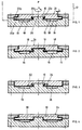
- In Fig. 1 ist, schematisch, eine erfindungsgemäss montierte Targetplatte 10 dargestellt. Eine strichpunktiert angedeutete Vakuumkammer 12 umfasst eine Kühlplatte 14 mit Kanälen 16 für ein Kühlmedium, flüssig oder gasförmig, üblicherweise für Wasser. Die Kanäle 16 in der Kühlplatte 14 sind gegen den Prozessraum P hin mit gut wärmedurchleitenden Membranen 18, vorzugsweise Metallfolien, dichtend verschlossen.
- Die Targetplatte 10 sowie die Kühlplatte 14 weisen je im Zentrum und an der Peripherie Bajonettverschlussteile auf, so die Targetplatte 10 radial aus- bzw. einspringende Partien 20p und 20z und die Kühlplatte 14 entsprechende Bajonettverschlusspartien 22p bzw. 22z. Dabei bilden die Teile 22p Teil der Kammerwand der Vakuumkammer 12. Die kühlplatten- und targetplattenseitigen Bajonettverschlussteile 20, 22 gemäss Fig. 1 bilden zwei koaxial angeordnete Bajonettverschlüsse, entsprechend den Indices p und z, welche, wie mit dem Pfeil b dargestellt, durch Verschwenken der Targetplatte im wesentlichen parallel zu der dem Prozessraum P zugewandten Targetoberfläche 24 geschlossen bzw. geöffnet werden. Es wird auf das radiale Spiel zwischen Targetplatte 10 und kammerseitiger Trägeranordnung hingewiesen, das eine thermische Radialausdehnung der Platte 10 im wesentlichen spannungsfrei zulässt.
- Eine Ausbildung der Bajonettverschlussteile ist in den Fig. 5 bis 7 in Aufsicht dargestellt, wobei dort primär die Ausbildung des Peripherieverschlusses dargestellt ist, und, in den Fig. 5 und 6 gestrichelt, die zusätzliche Ausbildung des Zentralverschlusses, entsprechend den Indices z.
- Bei der Darstellung von Fig. 1 ist das Kühlmedium in den Kanälen 16 noch nicht unter Druck gesetzt. In diesem Zustand besteht zwischen Targetplatte und Kühlplatte axiales und radiales Spiel, so dass die Targetplatte 10 nach dem Aufsetzen auf die Kühlplatte leicht durch Drehen in das Bajonett geschoben werden kann. Dabei wird das Target trotz des radialen Spiels L im Peripheriebereich durch den zentralen Bajonettzapfen an der Kühlplatte 14, bei 26 eingetragen, gegenüber der Kühlplatte 14 zentriert.
- In Fig. 2 ist das Kühlmedium in den Kanälen 16 der Anordnung gemäss Fig. 1 unter Druck gesetzt, wodurch sich die Membrane 18, wie erwähnt vorzugsweise durch Metallfolien gebildet, gegen die Targetplatte 10 legt und diese axial im Rahmen des vorgesehenen axialen Spiels hochhebt. Dadurch wird der Bajonettverschluss verspannt und gleichzeitig ein guter Wärmeübergang von Targetplatte 10 über die Metallfolie 18 auf das Medium in den Kanälen 16 sichergestellt. Trotz des axialen Verspannens des Bajonettverschlusses bleibt das radiale Spiel L der Targetplatte 10 bezüglich der Kühlplatte 14 an der Vakuumkammer 12 bestehen, so dass sich die Targetplatte 10 thermisch frei radial ausdehnen kann. Bei axialer Ausdehnung arbeitet sie gegen den Druck des Mediums in den Kanälen 16. Dadurch werden thermisch bedingte Spannungen im Target reduziert und mithin Verformungen der Targetoberfläche 24.
- Damit wird grundsätzlich erreicht, dass Targetplatten 10 besser ausgenützt werden können, teilweise, wie in den Fig. 1 und 2 dargestellt, Targets ohne versteifende Platten einsetzbar sind und damit billiger werden und grössere Targetplatten realisiert werden können.
- Wie noch gezeigt werden wird, können anstelle von zentralen und peripheren Bajonettverschlüssen auch nur zentrale oder nur periphere eingesetzt werden, was sich nach den Dimensionen, insbesondere dem Verhältnis Targetausdehnung zu Targetdicke, und dem Targetmaterial - spröd oder eher duktil - und der Targetbetriebstemperatur entscheiden lässt.
- In Fig. 3 ist eine Targetplatte 10 analog zu Fig. 1 dargestellt, bei entspanntem Medium in den Kanälen 16, wobei die Bajonettverschlussanordnung lediglich einen Zentralbajonettverschluss umfasst.
- In Fig. 4 ist, analog, die entspannte Verschlussanordnung dargestellt mit nur peripherem Bajonettverschluss.
- Wie als Beispiel an der Anordnung gemäss Fig. 4 dargestellt, kann die eigentliche Targetplatte 10 mit der zu zerstäubenden Oberfläche 24 je nach Targetmaterial, Dimension und der Targetbetriebstemperatur auf eine Versteifungsplatte 30 montiert sein, beispielsweise gebondet sein, wobei dann, im Sinne der vorliegenden Erfindung, Platte 10 und Versteifungsplatte 30 gemeinsam die Targetplatte bilden.
- Im weiteren können, wie gestrichelt in Fig. 3 eingetragen, die den Bajonettverschlussteil oder die Bajonettverschlussteile an der Targetplatte 10 bildenden Partien durch separate Bauteile, Bajonettverschlussrahmen 32, gebildet sein, welche nach Verbrauch des Targets 10 wieder eingesetzt werden für ein nächstes Target und hierzu beispielsweise, wie bei 34 dargestellt, mit der Targetplatte verschraubt sind.
- Es hat sich gezeigt, dass die vorgeschlagene Technik sich insbesondere beim Einsatz von Aluminium- oder Aluminiumlegierungstargets ausgezeichnet eignet.
Claims (12)
- Verfahren zur Montage bzw. Demontage einer zu kühlenden Targetplatte in einem Vakuumprozessraum, bei welchem die Platte (10) mittels flächiger Auskragungen (20p, 20z) unter flächige Auskragungen (22p, 22z) an einem Träger (14) lose und im wesentlichen parallel zur Plattenebene eingeschoben wird, darnach die sich hintergreifenden Auskragungen durch Druckbeaufschlagung der Platte mittels eines Kühlmediums verspannt werden und umgekehrt für die Demontage, dadurch gekennzeichnet, dass die flächigen Auskragungen (20p, 20z; 22p, 22z) an Platte (10) und Träger (14) jeweils Aussparungen zwischen sich festlegen, die Auskragungen (20p, 20z) an der Platte (10) quer zur Plattenebene in die Aussparungen trägerseitig lose eingeführt werden und bajonettartig lose unter die trägerseitigen Auskragungen (22p, 22z) geschoben werden, dabei ein thermisch bedingter Verzug der Platte (10) durch Spiel der plattenseitigen Ausformungen (20p, 20z) bezüglich des Trägers (14) und der trägerseitigen Ausformungen (22p, 22z) bezüglich der Platte (10) vermieden wird.
- Verfahren nach Anspruch 1, dadurch gekennzeichnet, dass man durch eine Relativdrehung der Platte (10) die Auskragungen (20p, 20z) an der Platte (10) unter die trägerseitigen (22p, 22z) schiebt.
- Verfahren nach Anspruch 1 oder 2, dadurch gekennzeichnet, dass man Auskragungen an der Platte (10) sowie trägerseitig (14) im Zentrumsbereich und/oder im Peripheriebereich bezüglich der Platte (10) vorsieht.
- Verfahren nach einem der Ansprüche 1 bis 3, dadurch gekennzeichnet, dass man das Medium über eine Trennmembran, wie z.B. eine Metallfolie, auf die Platte (10) zur Wirkung bringt.
- Targetmontageanordnung zur Ausführung des Verfahrens nach einem der Ansprüche 1 bis 4 mit flächigen Auskragungen (20p, 20z) an einer Targetplatte (10) sowie flächigen Auskragungen (22p, 22z) an einem Targetträger (14), wobei die plattenseitigen Auskragungen (20p, 20z) unter die trägerseitigen (22p, 22z) im wesentlichen parallel zur Plattenebene lose einschiebbar sind, und mit einer targetseitigen Kanalanordnung (16) für ein Kühlmedium mit unter Druck des Mediums gegen die lose eingeschobene Platte (10) spannbarer, membranartiger Trennwand (18), dadurch gekennzeichnet, dass die flächigen Auskragungen (20p, 20z; 22p, 22z), träger(14)- und platten(10)seitig, zwischen sich Aussparungen aufweisen, derart, dass die plattenseitigen Auskragungen (20p, 20z) lose in die trägerseitigen Aussparungen quer zur Plattenebene einführbar sind und darnach, durch Relatiwerschiebung im wesentlichen parallel zur Plattenebene, die Auskragungen (20p, 20z; 22p, 22z) lose bajonettartig hinterhakbar sind, und dass weiter die plattenseitigen Auskragungen (20p, 20z) bezüglich des Trägers (14) und die trägerseitigen Auskragungen (22p, 22z) bezüglich der Targetplatte (10) Spiel aufweisen zur Aufnahme thermischer Plattenausdehnung.
- Anordnung nach Anspruch 5, dadurch gekennzeichnet, dass an der Platte Auskragungen (20p, 20z) in deren Mittenbereich angeordnet sind und/oder an deren Peripheriebereich.
- Anordnung nach einem der Ansprüche 5 oder 6, dadurch gekennzeichnet, dass die Platte (10) radial zu kammerseitigen Teilen (14) Spiel (L) aufweist.
- Targetplatte für eine Montageanordnung nach einem der Ansprüche 5 bis 7, dadurch gekennzeichnet, dass sie eine aus zu zerstäubendem Material bestehende Platte aufweist und eine Stabilisierungsplatte (30), worauf sie montiert ist, wie daran festgebondet ist, wobei die Auskragungen (20p, 20z) an der Stabilisierungsplatte vorgesehen sind.
- Targetplatte nach Anspruch 8, dadurch gekennzeichnet, dass die Auskragungen (20p, 20z) daran lösbar befestigt sind.
- Targetplatte für eine Montageanordnung nach einem der Ansprüche 5 bis 7, dadurch gekennzeichnet, dass die Auskragungen (20p, 20z) daran lösbar befestigt sind.
- Vakuumkammer mit einer Montageanordnung nach einem der Ansprüche 5 bis 7.
- Verwendung des Verfahrens nach einem der Ansprüche 1 bis 4 oder der Montageanordnung nach einem der Ansprüche 5 bis 7 an einer Targetplatte in einem Abstäubungs- oder Verdampfungsprozess zur Beschichtung eines Werkstückes, wie in einem Ionenstrahlzerstäubungsprozess, einem Plasmazerstäubungsprozess, einem Elektronenstrahlverdampfungsprozess oder einem Lichtbogenverdampfungsprozess, alle reaktiv oder nicht reaktiv.
Applications Claiming Priority (2)
| Application Number | Priority Date | Filing Date | Title |
|---|---|---|---|
| CH1386/91 | 1991-05-08 | ||
| CH138691 | 1991-05-08 |
Publications (2)
| Publication Number | Publication Date |
|---|---|
| EP0512456A1 EP0512456A1 (de) | 1992-11-11 |
| EP0512456B1 true EP0512456B1 (de) | 1997-06-18 |
Family
ID=4209217
Family Applications (1)
| Application Number | Title | Priority Date | Filing Date |
|---|---|---|---|
| EP92107498A Expired - Lifetime EP0512456B1 (de) | 1991-05-08 | 1992-05-04 | Verfahren zur Montage bzw. Demontage einer Targetplatte in einem Vakuumprozessraum, Montageanordnung hierfür sowie Targetplatte bzw. Vakuumkammer |
Country Status (5)
| Country | Link |
|---|---|
| US (1) | US5269894A (de) |
| EP (1) | EP0512456B1 (de) |
| JP (1) | JP3417578B2 (de) |
| KR (2) | KR100263136B1 (de) |
| DE (1) | DE59208623D1 (de) |
Cited By (2)
| Publication number | Priority date | Publication date | Assignee | Title |
|---|---|---|---|---|
| US6866676B2 (en) | 1992-06-02 | 2005-03-15 | General Surgical Innovations, Inc. | Apparatus and method for dissecting tissue layers |
| US6953467B2 (en) | 1992-06-02 | 2005-10-11 | General Surgical Innovations, Inc. | Apparatus and method for developing an anatomic space for laparoscopic hernia repair and patch for use therewith |
Families Citing this family (38)
| Publication number | Priority date | Publication date | Assignee | Title |
|---|---|---|---|---|
| US6689254B1 (en) * | 1990-10-31 | 2004-02-10 | Tokyo Electron Limited | Sputtering apparatus with isolated coolant and sputtering target therefor |
| DE9102052U1 (de) * | 1991-02-21 | 1991-06-13 | Hauzer Holding B.V., Venlo | Indirekt gekühlter Verdampfer mit Schnellwechselsystem |
| US5540711A (en) | 1992-06-02 | 1996-07-30 | General Surgical Innovations, Inc. | Apparatus and method for developing an anatomic space for laparoscopic procedures with laparoscopic visualization |
| US5286361A (en) * | 1992-10-19 | 1994-02-15 | Regents Of The University Of California | Magnetically attached sputter targets |
| DE4301516C2 (de) * | 1993-01-21 | 2003-02-13 | Applied Films Gmbh & Co Kg | Targetkühlung mit Wanne |
| CH690805A5 (de) * | 1993-05-04 | 2001-01-15 | Unaxis Balzers Ag | Magnetfeldunterstützte Zerstäubungsanordnung und Vakuumbehandlungsanlage hiermit. |
| CH687427A5 (de) * | 1993-10-13 | 1996-11-29 | Balzers Hochvakuum | Sputterquelle mit Targetanordnung und Halterung. |
| US5680013A (en) * | 1994-03-15 | 1997-10-21 | Applied Materials, Inc. | Ceramic protection for heated metal surfaces of plasma processing chamber exposed to chemically aggressive gaseous environment therein and method of protecting such heated metal surfaces |
| DE4410466C1 (de) * | 1994-03-25 | 1995-09-14 | Balzers Hochvakuum | Targethalterung, Target und ihre Verwendung |
| US5653726A (en) * | 1994-11-03 | 1997-08-05 | Archimedes Surgical, Inc. | Retrograde dissector and method for facilitating a TRAM flap |
| US5597459A (en) * | 1995-02-08 | 1997-01-28 | Nobler Technologies, Inc. | Magnetron cathode sputtering method and apparatus |
| DE19535894A1 (de) * | 1995-09-27 | 1997-04-03 | Leybold Materials Gmbh | Target für die Sputterkathode einer Vakuumbeschichtungsanlage und Verfahren zu seiner Herstellung |
| US5589003A (en) * | 1996-02-09 | 1996-12-31 | Applied Materials, Inc. | Shielded substrate support for processing chamber |
| US6068742A (en) * | 1996-07-22 | 2000-05-30 | Balzers Aktiengesellschaft | Target arrangement with a circular plate, magnetron for mounting the target arrangement, and process for coating a series of circular disc-shaped workpieces by means of said magnetron source |
| US6015421A (en) * | 1997-05-15 | 2000-01-18 | General Surgical Innovations, Inc. | Apparatus and method for developing an anatomic space for laparoscopic procedures |
| EP0951049A1 (de) * | 1998-04-16 | 1999-10-20 | Balzers Aktiengesellschaft | Haltering sowie Target und Verfahren zu seiner Herstellung |
| DE10016880A1 (de) | 2000-04-05 | 2001-10-18 | Bayerische Motoren Werke Ag | Schwingungsdämpfer für eine hydraulische Fahrzeug-Bremsanlage |
| EP1322444A4 (de) * | 2000-09-11 | 2008-01-23 | Tosoh Smd Inc | Verfahren zur herstellung von sputtertargets mit inneren kühlkanälen |
| US6503380B1 (en) * | 2000-10-13 | 2003-01-07 | Honeywell International Inc. | Physical vapor target constructions |
| JP3818084B2 (ja) * | 2000-12-22 | 2006-09-06 | 日立電線株式会社 | 冷却板とその製造方法及びスパッタリングターゲットとその製造方法 |
| FR2842348B1 (fr) * | 2002-07-10 | 2004-09-10 | Tecmachine | Cathode pour pulverisation sous vide |
| FR2842347B1 (fr) * | 2002-07-10 | 2004-12-03 | Tecmachine | Cathode pour machine de traitement par pulverisation sous vide |
| KR20060029622A (ko) * | 2003-06-20 | 2006-04-06 | 캐보트 코포레이션 | 백킹 플레이트에 스퍼터 타겟 부착을 위한 방법 및 디자인 |
| KR100989156B1 (ko) * | 2003-12-18 | 2010-10-20 | 엘지디스플레이 주식회사 | 화학기상 증착장비 |
| PL1609880T3 (pl) * | 2004-06-22 | 2008-10-31 | Applied Mat Gmbh & Co Kg | Katoda do rozpylania jonowego do procesów nakładania powłok |
| TW200710243A (en) * | 2005-05-02 | 2007-03-16 | Honeywell Int Inc | Target assemblies, targets, backing plates, and methods of target cooling |
| EP1835525A1 (de) * | 2006-03-16 | 2007-09-19 | Sulzer Metco AG (Switzerland) | Targethaltevorrichtung |
| CA2577757A1 (en) * | 2006-03-16 | 2007-09-16 | Sulzer Metco Ag | Target holding apparatus |
| JP5465585B2 (ja) * | 2010-04-09 | 2014-04-09 | 住友重機械工業株式会社 | 成膜装置 |
| DE102012006717A1 (de) * | 2012-04-04 | 2013-10-10 | Oerlikon Trading Ag, Trübbach | An eine indirekte Kühlvorrichtung angepasstes Target |
| SG11201508324VA (en) * | 2013-04-08 | 2015-11-27 | Oerlikon Surface Solutions Ag Trubbach | Centering of a plate in a holder both at room temperatures and at higher temperatures |
| DE102013011074A1 (de) * | 2013-07-03 | 2015-01-08 | Oerlikon Trading Ag | An eine indirekte Kühlvorrichtung angepasstes Target mit Kühlplatte |
| MX2019014425A (es) | 2017-06-01 | 2020-02-10 | Oerlikon Surface Solutions Ag Pfaeffikon | Conjunto de blanco para la evaporación segura y económica de materiales frágiles. |
| CN108203812B (zh) * | 2018-01-25 | 2020-02-07 | 京东方科技集团股份有限公司 | 一种基板固定载具、蒸镀设备及蒸镀方法 |
| US20210025050A1 (en) * | 2018-03-30 | 2021-01-28 | Jfe Steel Corporation | Target exchanging device and surface treatment facility |
| US11600517B2 (en) * | 2018-08-17 | 2023-03-07 | Taiwan Semiconductor Manufacturing Co., Ltd. | Screwless semiconductor processing chambers |
| CN110838458B (zh) | 2018-08-17 | 2022-08-09 | 台湾积体电路制造股份有限公司 | 半导体制程系统以及方法 |
| DE102023114526B3 (de) | 2023-06-02 | 2024-11-28 | Carl Zeiss Sms Ltd. | Vakuumkammer, Vorrichtung und Verfahren |
Citations (2)
| Publication number | Priority date | Publication date | Assignee | Title |
|---|---|---|---|---|
| US4657654A (en) * | 1984-05-17 | 1987-04-14 | Varian Associates, Inc. | Targets for magnetron sputter device having separate confining magnetic fields to separate targets subject to separate discharges |
| EP0499770A2 (de) * | 1991-02-21 | 1992-08-26 | Hauzer Holding B.V. | Indirekt gekühltes Target mit Schnellwechselsystem |
Family Cites Families (6)
| Publication number | Priority date | Publication date | Assignee | Title |
|---|---|---|---|---|
| JPH0739630B2 (ja) * | 1986-02-26 | 1995-05-01 | 株式会社日立製作所 | 真空蒸着装置 |
| EP0393344A1 (de) * | 1989-04-20 | 1990-10-24 | Balzers Aktiengesellschaft | Haltevorrichtung für Targets von Zerstäubungsquellen und Verfahren zum Festhalten eines Targets in einer Halterung |
| DE59009549D1 (de) * | 1989-06-05 | 1995-09-28 | Balzers Hochvakuum | Verfahren zum Kühlen von Targets sowie Kühleinrichtung für Targets. |
| DE4015388C2 (de) * | 1990-05-14 | 1997-07-17 | Leybold Ag | Kathodenzerstäubungsvorrichtung |
| US5032246A (en) * | 1990-05-17 | 1991-07-16 | Tosoh Smd, Inc. | Sputtering target wrench and sputtering target design |
| US5009765A (en) * | 1990-05-17 | 1991-04-23 | Tosoh Smd, Inc. | Sputter target design |
-
1992
- 1992-05-04 EP EP92107498A patent/EP0512456B1/de not_active Expired - Lifetime
- 1992-05-04 US US07/878,049 patent/US5269894A/en not_active Expired - Lifetime
- 1992-05-04 DE DE59208623T patent/DE59208623D1/de not_active Expired - Lifetime
- 1992-05-08 KR KR1019920007833A patent/KR100263136B1/ko not_active Expired - Lifetime
- 1992-05-08 JP JP15997692A patent/JP3417578B2/ja not_active Expired - Fee Related
-
2000
- 2000-01-27 KR KR1020000003946A patent/KR100403567B1/ko not_active Expired - Lifetime
Patent Citations (2)
| Publication number | Priority date | Publication date | Assignee | Title |
|---|---|---|---|---|
| US4657654A (en) * | 1984-05-17 | 1987-04-14 | Varian Associates, Inc. | Targets for magnetron sputter device having separate confining magnetic fields to separate targets subject to separate discharges |
| EP0499770A2 (de) * | 1991-02-21 | 1992-08-26 | Hauzer Holding B.V. | Indirekt gekühltes Target mit Schnellwechselsystem |
Cited By (3)
| Publication number | Priority date | Publication date | Assignee | Title |
|---|---|---|---|---|
| US6866676B2 (en) | 1992-06-02 | 2005-03-15 | General Surgical Innovations, Inc. | Apparatus and method for dissecting tissue layers |
| US6953467B2 (en) | 1992-06-02 | 2005-10-11 | General Surgical Innovations, Inc. | Apparatus and method for developing an anatomic space for laparoscopic hernia repair and patch for use therewith |
| US7297153B2 (en) | 1992-06-02 | 2007-11-20 | General Surgical Innovations, Inc. | Apparatus and method for developing an anatomic space for laparoscopic hernia repair and patch for use therewith |
Also Published As
| Publication number | Publication date |
|---|---|
| KR100263136B1 (ko) | 2000-08-01 |
| EP0512456A1 (de) | 1992-11-11 |
| KR920021732A (ko) | 1992-12-18 |
| DE59208623D1 (de) | 1997-07-24 |
| JP3417578B2 (ja) | 2003-06-16 |
| KR100403567B1 (ko) | 2003-11-01 |
| JPH05171429A (ja) | 1993-07-09 |
| US5269894A (en) | 1993-12-14 |
Similar Documents
| Publication | Publication Date | Title |
|---|---|---|
| EP0512456A1 (de) | Verfahren zur Montage bzw. Demontage einer Targetplatte in einem Vakuumprozessraum, Montageanordnung hierfür sowie Targetplatte bzw. Vakuumkammer | |
| EP0165565B1 (de) | Vakuum-Plasma-Beschichtungsanlage | |
| DE69023633T2 (de) | Kathodenzerstäubungsgerät und kathodenzerstäubungsanlage. | |
| DE69011052T2 (de) | Chemische Gasphasen-Beschichtungsanlage der In-Line-Bauart. | |
| DE68915014T2 (de) | Gerät zur Bildung dünner Schichten und durch Mikrowellen-Zerstäubung arbeitende Ionenquelle. | |
| DE102005050358B4 (de) | Vakuumbehandlungsanlage | |
| AT407995B (de) | Einrichtung zur vakuumbeschichtung von gleitlagern | |
| DE4410466C1 (de) | Targethalterung, Target und ihre Verwendung | |
| EP0499770A2 (de) | Indirekt gekühltes Target mit Schnellwechselsystem | |
| DE3850941T2 (de) | Vakuumbeschichtungsanlage. | |
| DE69018580T2 (de) | Zerstäubungsgerät. | |
| CH692000A5 (de) | Beschichtungskammer, Substratträger hierfür, Verfahren zum Vakuumbedampfen sowie Beschichtungsverfahren. | |
| EP2834389B1 (de) | Beschichtungsquelle mit einem an eine indirekte kühlvorrichtung angepassten target | |
| CH621580A5 (de) | ||
| EP0438627B1 (de) | Bogenentladungsverdampfer mit mehreren Verdampfertiegeln | |
| DE69128544T2 (de) | Verfahren und vorrichtung zur sputtenbeschichtung mit rotierender magnetischer kathode | |
| DE3787390T2 (de) | Kathoden- und Target-Anordnung für eine Beschichtungsvorrichtung zum Zerstäuben. | |
| EP0282540B1 (de) | Verfahren und vorrichtung zum metallisieren von folienoberflächen | |
| EP1849886A1 (de) | Einrichtung und Verfahren zur plasmagestützten Abscheidung von Hartstoffschichten | |
| EP1306463B1 (de) | Plattenträger | |
| EP1520290B1 (de) | Vorrichtung zur beschichtung von substraten mittels physikalischer dampfabscheidung über den hohlkathodeneffekt | |
| DE69501139T2 (de) | Kathodenzerstäubungs-Drehkathode mit mehreren Targets | |
| EP0897189B1 (de) | Hochdruck-Magnetron-Kathode sowie eine solche enthaltende Vorrichtung | |
| EP4131332A1 (de) | Mehrfach-sputtertarget | |
| EP0507113B1 (de) | Verfahren zur Beschichtung eines Werkstückes aus Kunststoff mit einer Metallschicht |
Legal Events
| Date | Code | Title | Description |
|---|---|---|---|
| PUAI | Public reference made under article 153(3) epc to a published international application that has entered the european phase |
Free format text: ORIGINAL CODE: 0009012 |
|
| AK | Designated contracting states |
Kind code of ref document: A1 Designated state(s): CH DE FR GB LI NL |
|
| 17P | Request for examination filed |
Effective date: 19930423 |
|
| 17Q | First examination report despatched |
Effective date: 19940727 |
|
| GRAG | Despatch of communication of intention to grant |
Free format text: ORIGINAL CODE: EPIDOS AGRA |
|
| GRAH | Despatch of communication of intention to grant a patent |
Free format text: ORIGINAL CODE: EPIDOS IGRA |
|
| GRAH | Despatch of communication of intention to grant a patent |
Free format text: ORIGINAL CODE: EPIDOS IGRA |
|
| GRAA | (expected) grant |
Free format text: ORIGINAL CODE: 0009210 |
|
| AK | Designated contracting states |
Kind code of ref document: B1 Designated state(s): CH DE FR GB LI NL |
|
| PG25 | Lapsed in a contracting state [announced via postgrant information from national office to epo] |
Ref country code: FR Effective date: 19970618 |
|
| REG | Reference to a national code |
Ref country code: CH Ref legal event code: EP |
|
| GBT | Gb: translation of ep patent filed (gb section 77(6)(a)/1977) |
Effective date: 19970619 |
|
| REF | Corresponds to: |
Ref document number: 59208623 Country of ref document: DE Date of ref document: 19970724 |
|
| EN | Fr: translation not filed | ||
| PLBE | No opposition filed within time limit |
Free format text: ORIGINAL CODE: 0009261 |
|
| STAA | Information on the status of an ep patent application or granted ep patent |
Free format text: STATUS: NO OPPOSITION FILED WITHIN TIME LIMIT |
|
| 26N | No opposition filed | ||
| REG | Reference to a national code |
Ref country code: GB Ref legal event code: IF02 |
|
| REG | Reference to a national code |
Ref country code: CH Ref legal event code: PFA Owner name: OC OERLIKON BALZERS AG Free format text: BALZERS AKTIENGESELLSCHAFT# #9496 BALZERS (LI) -TRANSFER TO- OC OERLIKON BALZERS AG#PATENTABTEILUNG POSTFACH 1000#9496 BALZERS (LI) |
|
| REG | Reference to a national code |
Ref country code: CH Ref legal event code: PUE Owner name: OERLIKON TRADING AG, TRUEBBACH Free format text: OC OERLIKON BALZERS AG#PATENTABTEILUNG POSTFACH 1000#9496 BALZERS (LI) -TRANSFER TO- OERLIKON TRADING AG, TRUEBBACH#HAUPTSTRASSE#9477 TRUEBBACH (CH) |
|
| REG | Reference to a national code |
Ref country code: GB Ref legal event code: 732E |
|
| NLS | Nl: assignments of ep-patents |
Owner name: OERLIKON TRADING AG, TRUEBBACH Effective date: 20080618 |
|
| NLT1 | Nl: modifications of names registered in virtue of documents presented to the patent office pursuant to art. 16 a, paragraph 1 |
Owner name: UNAXIS BALZERS AKTIENGESELLSCHAFT Owner name: OC OERLIKON BALZERS AG |
|
| PGFP | Annual fee paid to national office [announced via postgrant information from national office to epo] |
Ref country code: NL Payment date: 20080703 Year of fee payment: 18 |
|
| REG | Reference to a national code |
Ref country code: NL Ref legal event code: V1 Effective date: 20101201 |
|
| PG25 | Lapsed in a contracting state [announced via postgrant information from national office to epo] |
Ref country code: NL Free format text: LAPSE BECAUSE OF NON-PAYMENT OF DUE FEES Effective date: 20101201 |
|
| PGFP | Annual fee paid to national office [announced via postgrant information from national office to epo] |
Ref country code: GB Payment date: 20110504 Year of fee payment: 20 |
|
| PGFP | Annual fee paid to national office [announced via postgrant information from national office to epo] |
Ref country code: DE Payment date: 20110427 Year of fee payment: 20 |
|
| PGFP | Annual fee paid to national office [announced via postgrant information from national office to epo] |
Ref country code: CH Payment date: 20110825 Year of fee payment: 20 |
|
| REG | Reference to a national code |
Ref country code: DE Ref legal event code: R071 Ref document number: 59208623 Country of ref document: DE |
|
| REG | Reference to a national code |
Ref country code: CH Ref legal event code: PL |
|
| REG | Reference to a national code |
Ref country code: GB Ref legal event code: PE20 Expiry date: 20120503 |
|
| PG25 | Lapsed in a contracting state [announced via postgrant information from national office to epo] |
Ref country code: GB Free format text: LAPSE BECAUSE OF EXPIRATION OF PROTECTION Effective date: 20120503 |
|
| PG25 | Lapsed in a contracting state [announced via postgrant information from national office to epo] |
Ref country code: DE Free format text: LAPSE BECAUSE OF EXPIRATION OF PROTECTION Effective date: 20120505 |