EP0512461A2 - Machine d'usinage des pièces en bois, plastique ou similaires - Google Patents
Machine d'usinage des pièces en bois, plastique ou similaires Download PDFInfo
- Publication number
- EP0512461A2 EP0512461A2 EP92107514A EP92107514A EP0512461A2 EP 0512461 A2 EP0512461 A2 EP 0512461A2 EP 92107514 A EP92107514 A EP 92107514A EP 92107514 A EP92107514 A EP 92107514A EP 0512461 A2 EP0512461 A2 EP 0512461A2
- Authority
- EP
- European Patent Office
- Prior art keywords
- workpieces
- closing part
- machine
- workpiece
- insertion opening
- Prior art date
- Legal status (The legal status is an assumption and is not a legal conclusion. Google has not performed a legal analysis and makes no representation as to the accuracy of the status listed.)
- Granted
Links
Images

Classifications
-
- B—PERFORMING OPERATIONS; TRANSPORTING
- B23—MACHINE TOOLS; METAL-WORKING NOT OTHERWISE PROVIDED FOR
- B23Q—DETAILS, COMPONENTS, OR ACCESSORIES FOR MACHINE TOOLS, e.g. ARRANGEMENTS FOR COPYING OR CONTROLLING; MACHINE TOOLS IN GENERAL CHARACTERISED BY THE CONSTRUCTION OF PARTICULAR DETAILS OR COMPONENTS; COMBINATIONS OR ASSOCIATIONS OF METAL-WORKING MACHINES, NOT DIRECTED TO A PARTICULAR RESULT
- B23Q11/00—Accessories fitted to machine tools for keeping tools or parts of the machine in good working condition or for cooling work; Safety devices specially combined with or arranged in, or specially adapted for use in connection with, machine tools
- B23Q11/08—Protective coverings for parts of machine tools; Splash guards
-
- B—PERFORMING OPERATIONS; TRANSPORTING
- B27—WORKING OR PRESERVING WOOD OR SIMILAR MATERIAL; NAILING OR STAPLING MACHINES IN GENERAL
- B27G—ACCESSORY MACHINES OR APPARATUS FOR WORKING WOOD OR SIMILAR MATERIALS; TOOLS FOR WORKING WOOD OR SIMILAR MATERIALS; SAFETY DEVICES FOR WOOD WORKING MACHINES OR TOOLS
- B27G21/00—Safety guards or devices specially designed for other wood-working machines auxiliary devices facilitating proper operation of said wood-working machines
-
- F—MECHANICAL ENGINEERING; LIGHTING; HEATING; WEAPONS; BLASTING
- F16—ENGINEERING ELEMENTS AND UNITS; GENERAL MEASURES FOR PRODUCING AND MAINTAINING EFFECTIVE FUNCTIONING OF MACHINES OR INSTALLATIONS; THERMAL INSULATION IN GENERAL
- F16P—SAFETY DEVICES IN GENERAL; SAFETY DEVICES FOR PRESSES
- F16P1/00—Safety devices independent of the control and operation of any machine
- F16P1/005—Guards for rolls in calendering or other roll machines, e.g. nip guards, finger guards
Definitions
- the invention relates to a processing machine for workpieces made of wood, plastic and the like. According to the preamble of claim 1.
- the workpieces to be processed are placed on the transport path from an input area and then transported through the machine by means of a feed device.
- the workpiece is machined in the machine using the appropriate tool.
- This creates chips, splinters and the like, which are thrown out through the insertion opening.
- the insertion opening is partially covered by the inlet protection, the insertion opening is open over the height of the workpiece.
- the operator is adversely affected by the chips, splinters and the like that fly out through the insertion opening. As a result of the high force with which these chips fly through the insertion opening, there is also a considerable risk of injury to the operator.
- the invention has for its object to design the generic processing machine so that the chips, splinters and the like inevitably occurring when machining the workpieces cannot impair or endanger the operator.
- the area below the inlet protection is now closed by the closing part.
- the insertion opening is completely closed by the inlet protection and this closing part, so that chips, splinters and the like which arise during the machining of the workpiece are no longer thrown out through the insertion opening.
- the closing part is adjustable transversely to the direction of advance of the workpieces, it is pushed back only so far during the passage of the workpieces that it lies against the workpiece, so that the insertion opening is completely closed except for the passage area for the respective workpiece.
- the securing device is part of a processing machine for wood, in particular window woods, plastic and the like.
- a processing machine has, in a known manner, at least one spindle on which a corresponding tool, preferably a profiling tool, is seated, with which the workpiece 1 (FIG. 2) is processed becomes.
- the workpiece 1 which is a window wood in the exemplary embodiment, is transported in its longitudinal direction through the machine.
- a transport path 3 is provided on a machine table 2, on which the workpiece 1 is transported through the machine in its longitudinal direction.
- the workpiece 1 rests against a stop 4 with its long side on the right in FIG. 2.
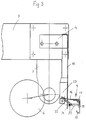
- the machine To transport the workpiece 1, the machine is provided in a known manner with a feed bar 5 (FIG. 3) on which feed rollers 6, driven in a known manner, are mounted one behind the other in the transport direction.
- a feed bar 5 (FIG. 3) on which feed rollers 6, driven in a known manner, are mounted one behind the other in the transport direction.
- Fig. 3 of the feed bar 5 only the end lying in the inlet area of the workpiece 1 is shown.
- at least one feed roller 6 is pivotally mounted on a holder 7 in the height direction. It projects from the feed beam 5 downwards in the direction of the transport path 3.
- the height of the feed bar 5 is adjusted in a known manner so that the feed rollers 6 mounted on it rest on the workpiece and transport it through the machine. 2 are the clarity because of the feed bar 5 and the feed rollers 6 not shown.
- the workpieces 1 to be machined are entered into the machine by an operator from the input area 8 (FIG. 1).
- the workpiece 1 is placed against the stop 4 extending in the feed direction of the workpiece 1, so that it is aligned precisely with the machining spindle with the tool seated thereon.
- the processing machine itself is not shown for the sake of clarity, but merely a securing device with which it is prevented that the operator brings the hand or hands too far into the machine when entering the workpieces 1 to be machined.
- this securing device reliably prevents, in a manner yet to be described, chips or splinters which arise during the machining of the workpiece 1 from being thrown outward into the input region 8.
- the securing device also prevents the entire workpiece 1 from being inadvertently kicked back.
- the inlet area 8 for the workpieces 1 to be machined is closed by an inlet protection 9 such that the user who enters the workpieces 1 into the machine cannot be accidentally pulled through the workpiece into the machine. If this happens, then the machine is stopped immediately by the run-in protection 9 in a manner to be described.
- the spindle (not shown) with the tool sits in a known manner under a cover 10 (FIG. 2), one side wall 10a of which has a corresponding rectangular opening 11, which forms an insertion opening for the workpieces 1. It is delimited on one side by the vertical edge 10b on the right in FIG. 2 and at the top by the upper horizontal edge 10c of the side wall 10a.
- the insertion opening 11 is delimited downwards by the machine table 2 and in FIG. 2 to the right by a vertical plate-shaped side wall 12 which can be fastened to the machine table 2.
- the insertion opening 11 thus has a rectangular outline.
- the insertion opening 11, as shown in FIG. 2, is covered over the largest part of its height during the passage of the workpieces 1 through the machine by the inlet protection. It is attached to the inlet-side end of the feed beam 5 via a plate-shaped protective wall 13 and via a fastening tab 14 which is fastened to the upper end of the protective wall 13. As a result, the run-in protection 9 is carried along by the feed beam 5, so that the run-in protection is always arranged at the correct height in relation to the thickness of the workpiece 1 to be machined.
- the protective wall 13 extends beyond the insertion opening 11, as shown in FIG. 2.
- a plate-shaped connecting part 16 which is approximately the same width as the insertion opening 11 and extends at the free end of this connecting part 16, is perpendicular to the protective wall 13 and extends vertically outwards against the direction of advance 15 (FIG. 1) of the workpieces 1 hinged down flap 17 which is pivotable about a horizontal axis 18 (Fig. 3).
- the lower end 19 of the flap 17 is bent in the feed direction 15. This prevents the flap 17 from getting caught on the workpiece when the workpiece 1 enters the machine.
- a lever 20 is rigidly attached, which projects vertically from the flap 17 and extends horizontally.
- the free end 21 of the lever 20 is bent at right angles or carries at the free end a support piece running perpendicular to it, on which the free end of a pivot lever 22 rests. It is pivotally supported at its other end on a limit switch 23 which is attached to the rear of the protective wall 13.
- the inlet guard 9 is connected to the feed bar 5 such that it has a small distance from the workpiece when the workpieces 1 to be machined enter the machine, as shown in FIG. In this starting position, the flap 17 assumes the vertical position shown in FIG. 3. If the operator accidentally gets into the area of the flap 17 when entering the respective workpiece 1 into the machine, the flap pivots about the horizontal axis 18 in the feed direction 15.
- the lever 20, which is firmly connected to the flap 17, is pivoted upwards. About the support 21 of the lever 20, the pivot lever 22 is pivoted counterclockwise upwards. This actuates the limit switch 23, which immediately stops the machine. In this way, it is reliably prevented that the operator, if, for example, he gets stuck on the workpiece due to careless work and is pulled by this workpiece in the feed direction 15, reaches the area of the subsequent tool.
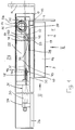
- the safety device 24 is also provided, which will be explained in more detail below with reference to FIGS. 1 and 2. It has a slide 25, which is mounted horizontally and perpendicular to the feed direction 15 on the machine.
- a bracket 26 is provided for mounting the carriage 25 and is fastened to the machine.
- This bracket 26 has guide rods 27 and 28 lying parallel to one another and in the region one above the other, on which the slide 25 is guided so as to be horizontally displaceable.
- the holder 26 carries a bearing piece 29 to which one end of a cylinder 30 of a piston-cylinder unit 31, preferably a pneumatic or hydraulic cylinder, is fastened.
- the free end of its piston rod 32 is fixed to the carriage 25.
- it has a corresponding holder 33 for the piston rod end at its end facing away from the cylinder 30.
- a guide piece 34 is provided, through which the cylinder 30 protrudes.
- a closing plate 35 is attached to the slide 25, which is arranged vertically and almost completely closes the insertion opening 11 when there is no workpiece 1 in the input area 8.
- This locking plate 35 extends vertically upward from the machine table 2 above the height of the connecting part 16 of the inlet protection 9.
- the upper horizontal edge 36 of the locking plate 35 (FIG. 2) is preferably in the upper third of the insertion opening 11. As shown in FIG. the closing plate 35 does not extend completely over the entire width of the insertion opening 11.
- the vertical edge 37 of the closing plate 35 facing away from the cylinder 30 lies, seen in the feed direction 15, at a distance from the side wall 12 which the insertion opening 11 is on the right in the feed direction 15 Side limited.
- This area is closed by a plate-shaped closing part 38, which is mounted on the rear side of the closing plate 35 facing away from the inlet protection and can be displaced horizontally relative to the closing plate 35 and can be tilted to a limited extent. At least from the closing plate 35 two bolts, screws 39 or the like, which protrude through horizontally running elongated holes 40 and 41 in the closing part 38. In the closed position shown in FIG. 1, the closing part 38 protrudes with its end facing away from the cylinder 30 beyond the closing plate 35, as a result of which the insertion opening 11 in the region below the inlet protection 9 is completely closed over the entire width.
- the locking part 38 has the same height as the locking plate 35, so that the upper horizontal edge 42 (FIG. 2) of the locking part 38 lies approximately at the same height as the upper horizontal edge 36 of the locking plate 35.
- the end of the closing part 38 facing away from the cylinder 30 is designed as a trigger member 43 or has such a trigger member 43.
- it is formed by a square tube which is fastened to the side of the closing part 38 facing the inlet protection 9 and is arranged in an upright position.
- the locking part 38 which is parallel to the locking plate 35, is at a short distance from it, so that the pivoting movement of the locking part 38, which will be described later, relative to the locking plate 35 is made possible.
- the end of the closing part 38 facing away from the trigger member 43 is bent at a right angle and has a passage opening 44 for a holding part 45. It is fastened in the guide piece 34 of the slide 25 and projects horizontally from it in the direction of the fastening tab 14 projecting perpendicularly from the protective wall 13.
- the holding part 45 is preferably formed by a threaded rod, on the end of which projects through the passage opening 44, a nut 46 is screwed.
- the holding part 45 is in the area between the guide piece 34 and the angled end 47 of the closing part 38 surrounded by a compression spring 48. It presses the free end 47 against the nut 46.
- a roller 49 of a contact lever 50 of a limit switch 51 bears against the side of the closing part 38 facing away from the closing plate 35.
- a run-up cam 52 is fastened to this rear side of the closing part 38, which is arranged horizontally and has a run-up surface 53 running in the direction of the cylinder 30. In the starting position shown in FIG. 1, in which the closing plate 35 and the closing part 38 close the insertion opening 11 in the area below the inlet protection 9, the roller 49 lies directly in front of the run-on surface 53 on the rear side of the closing part 38.
- the carriage 25 also carries a return safety device 54 for the workpiece 1. It is formed by a roller which is mounted on the carriage 25 so as to be rotatable about a vertical axis 55.
- the roller 54 is a freewheel roller which is freely rotatable counterclockwise, but is locked against rotation in the clockwise direction. As shown in FIG. 2, the roller 54 also extends from the machine table 2 to the level of the upper edges 36 and 42 of the closing plate 35 and the closing part 38.
- the roller 54 is provided on the jacket with teeth 56 (FIG. 1) which are provided over the entire circumference and over the entire height of the roller.
- the run-in protection 9 assumes the position shown in FIG. 3.
- the safety device 24 is here in the starting position according to FIG. 1, in which the carriage 25 assumes its end position on the right in FIG. 1.
- the striker 35 and the closing part 38 close the insertion opening 11 in the area below the inlet protection 9.
- the piston rod 32 is extended to the maximum.
- the passage opening 44 at the free end 47 of the closing part 38 is designed so that this small pivoting angle, which is only in the order of magnitude of, for example, about 2 to 4 °, is ensured.
- the contact lever 50 is pivoted back clockwise from the initial position shown in FIG. 1, as a result of which the limit switch 51 is actuated. It sends a signal to a control (not shown) for the piston-cylinder unit 31.
- the piston rod 32 is retracted by this signal, as a result of which the slide 25 with the closing plate 35, the closing part 38, the limit switch 51 and the roller 54 is pushed back will.
- the closing part 38 pivots back into its starting position shown in FIG. 1.
- the contact lever 50 then pivots back counterclockwise, whereby the limit switch 51 is actuated again and emits a corresponding signal to the piston-cylinder unit 31, which then extends the piston rod 32 again.
- the carriage 25 is moved back again until the roller 54 comes to rest on the longitudinal side of the workpiece 1 which is on the left in the feed direction 15.
- the trigger member 43 can be adjusted by means of the nut 46 so that it is on the workpiece 1 is not present, but has a small distance from it. This allows the workpiece to be transported through the machine without hindrance. In particular, it can thereby be ensured that the roller 54 with its teeth 56 perfectly engages with the workpiece 1 passing through the machine. If the workpiece 1 is transported through the machine in the feed direction 15, then the roller 54 is rotated counterclockwise in FIG. 1 about its vertical axis 55.
- the insertion opening 11 is completely closed by the inlet protection 9 and on the sides by the side wall 12 and the closing part 38 except for the area of the workpiece 1. This reliably prevents chips or splinters from escaping through the insertion opening 11 during the machining of the workpiece 1 with the tool.
- the roller 54 forms the backflow protection for the workpiece 1. It prevents the workpiece 1 from being pushed back against the feed direction 15. If the workpiece 1 experiences a force against the feed direction 15, then it cannot be thrown back because the roller 54 is locked against rotation in the clockwise direction. The teeth 56 of the roller 54 engaging in the workpiece 1 then prevent the workpiece 1 from being hit back. As a result of this safety device 24, it is thus excluded that the workpiece 1 inadvertently strikes back against the feed direction 15 and injures the operator.
- the roller 54 is securely engaged with the workpiece 1 passing through the machine because the piston-cylinder unit 31 constantly exerts pressure on the carriage 25 in the direction of the end position shown in FIG. 1. As soon as the workpiece 1 has passed the trigger member 43 and the roller 54, the slide 25 is thus immediately advanced into the end position shown in FIG. 1, in which the insertion opening 11 is completely closed again in the manner described.
- the machine offers the highest level of safety. Since the insertion opening 11 is completely closed in the manner described when the workpieces 1 pass through, except for the passage area of the workpiece, chips, splinters and the like cannot be thrown out through the insertion opening 11 during machining of the workpiece 1 and injure the operator could. If the operator accidentally pulls his hand through the insertion opening 11 gripping or, for example, getting caught on the workpiece 1 and thereby being pulled in the direction of the insertion opening 11, the flap 17 of the inlet protection 9 immediately stops the machine in the manner described. In the same way, the trigger member 43 ensures that the machine is stopped immediately if the operator accidentally puts his hand between the workpiece 1 and the trigger member 43 during machining.
Landscapes
- Engineering & Computer Science (AREA)
- Mechanical Engineering (AREA)
- Life Sciences & Earth Sciences (AREA)
- General Engineering & Computer Science (AREA)
- Wood Science & Technology (AREA)
- Forests & Forestry (AREA)
- Auxiliary Devices For Machine Tools (AREA)
Applications Claiming Priority (2)
| Application Number | Priority Date | Filing Date | Title |
|---|---|---|---|
| DE4115062A DE4115062A1 (de) | 1991-05-08 | 1991-05-08 | Bearbeitungsmaschine fuer werkstuecke aus holz, kunststoff und dergleichen |
| DE4115062 | 1991-05-08 |
Publications (3)
| Publication Number | Publication Date |
|---|---|
| EP0512461A2 true EP0512461A2 (fr) | 1992-11-11 |
| EP0512461A3 EP0512461A3 (en) | 1993-05-19 |
| EP0512461B1 EP0512461B1 (fr) | 1995-11-22 |
Family
ID=6431265
Family Applications (1)
| Application Number | Title | Priority Date | Filing Date |
|---|---|---|---|
| EP92107514A Expired - Lifetime EP0512461B1 (fr) | 1991-05-08 | 1992-05-04 | Machine d'usinage des pièces en bois, plastique ou similaires |
Country Status (2)
| Country | Link |
|---|---|
| EP (1) | EP0512461B1 (fr) |
| DE (2) | DE4115062A1 (fr) |
Cited By (1)
| Publication number | Priority date | Publication date | Assignee | Title |
|---|---|---|---|---|
| CN115723219A (zh) * | 2022-11-17 | 2023-03-03 | 浙江诚悦家具集团有限公司 | 一种定制衣柜的生产组件及方法 |
Family Cites Families (9)
| Publication number | Priority date | Publication date | Assignee | Title |
|---|---|---|---|---|
| US1430983A (en) * | 1921-10-05 | 1922-10-03 | Granberg Wilhelm | Guard for sawing machines |
| GB627645A (en) * | 1947-11-29 | 1949-08-12 | William James Pirie | Improvements in safety machinery guards |
| GB653866A (en) * | 1948-07-15 | 1951-05-30 | British Transp Commission | Improvements in guards for sewing machines |
| GB1443001A (en) * | 1973-03-28 | 1976-07-21 | Dunlop Ltd | Safety devices for machine tools |
| FR2268609A1 (en) * | 1974-04-26 | 1975-11-21 | Fagueret Henri | Safety device for woodworking machine - has plate over cutter raised and lowered by sensors actuated by workpiece |
| FR2620074B1 (fr) * | 1987-09-08 | 1992-05-15 | Nat Essais Lab | Dispositif de securite pour machine a bois, comportant un ecran mobile |
| FR2620075B1 (fr) * | 1987-09-08 | 1992-03-06 | Nat Essais Lab | Dispositif de securite a ecran mobile pour machines a bois |
| DE8810390U1 (de) * | 1988-08-17 | 1989-12-28 | Heinrichs, Peter, 6501 Sörgenloch | Motorangetriebene bewegliche Schutzscheibe für die Arbeitsplatzsicherung an Fließbandbetriebspunkten, Press-, Stanz-, Schweißanlagen o.dgl. |
| CA1301600C (fr) * | 1988-11-04 | 1992-05-26 | Serge Masse | Dispositif anti-rebond pour machine de traitement du bois |
-
1991
- 1991-05-08 DE DE4115062A patent/DE4115062A1/de not_active Withdrawn
-
1992
- 1992-05-04 EP EP92107514A patent/EP0512461B1/fr not_active Expired - Lifetime
- 1992-05-04 DE DE59204393T patent/DE59204393D1/de not_active Expired - Fee Related
Cited By (1)
| Publication number | Priority date | Publication date | Assignee | Title |
|---|---|---|---|---|
| CN115723219A (zh) * | 2022-11-17 | 2023-03-03 | 浙江诚悦家具集团有限公司 | 一种定制衣柜的生产组件及方法 |
Also Published As
| Publication number | Publication date |
|---|---|
| EP0512461B1 (fr) | 1995-11-22 |
| DE59204393D1 (de) | 1996-01-04 |
| DE4115062A1 (de) | 1992-11-12 |
| EP0512461A3 (en) | 1993-05-19 |
Similar Documents
| Publication | Publication Date | Title |
|---|---|---|
| DE1910977C3 (de) | Spannvorrichtung an einer Werkbank | |
| DE3233696C2 (fr) | ||
| DE4027316A1 (de) | Vorrichtung zum einstellen der position eines saegeblattes | |
| EP3175961B1 (fr) | Dispositif de compression pour une machine-outil servant à l'usinage de pièces en bois, en matière plastique et similaire et machine-outil comprenant au moins un dispositif de compression | |
| EP0654333A1 (fr) | Machine à travailler des pièces à usiner en bois, plastique ou similaires | |
| EP2199000B1 (fr) | Machine-outil, notamment scie circulaire et à onglet | |
| EP0512461B1 (fr) | Machine d'usinage des pièces en bois, plastique ou similaires | |
| DE3509227C2 (fr) | ||
| DE4025440A1 (de) | Tischsaege | |
| DE4007590A1 (de) | Werkstueckspanner | |
| DE10001029A1 (de) | Vorrichtung zum Bearbeiten von Baumstämmen | |
| DE1703446B2 (de) | Kappvorrichtung für Furnierkanten | |
| EP2198999B1 (fr) | Machine-outil, notamment scie circulaire et à onglet | |
| EP0629476B1 (fr) | Machine à travailler des pièces à usiner en bois, plastique ou similaires | |
| EP1704939B1 (fr) | Dispositif d'alimentation de fils, en particulier vers machines de soudage | |
| DE1528003A1 (de) | Vorrichtung zum Bearbeiten von plattenfoermigen Werkstuecken | |
| DE2111102C2 (de) | Maschine zum Herstellen von Streifen von stabförmigen Befestigungsmitteln | |
| DE2457630C3 (de) | Bewegliche Sicherheitsabschirmung für kraftbetriebene Pressen | |
| DE4016591C2 (de) | Maschine zum Bearbeiten von Werkstücken, insbesondere aus Holz | |
| DE290052C (fr) | ||
| DE4218932C1 (en) | Length stop for machines handling elongated workpieces - uses workpiece flank pressure to deactivate stop mechanism | |
| DE2332921C2 (de) | Anschlagvorrichtung | |
| DE29517466U1 (de) | Schneidmaschine | |
| DE3918900C2 (de) | Bearbeitungsmaschine mit einem Werkzeugspindelträgermagazin | |
| DE2443550C3 (de) | Werkstücktisch zum Anbau von Handkreissägen |
Legal Events
| Date | Code | Title | Description |
|---|---|---|---|
| PUAI | Public reference made under article 153(3) epc to a published international application that has entered the european phase |
Free format text: ORIGINAL CODE: 0009012 |
|
| AK | Designated contracting states |
Kind code of ref document: A2 Designated state(s): BE DE FR GB IT SE |
|
| PUAL | Search report despatched |
Free format text: ORIGINAL CODE: 0009013 |
|
| AK | Designated contracting states |
Kind code of ref document: A3 Designated state(s): BE DE FR GB IT SE |
|
| 17P | Request for examination filed |
Effective date: 19931020 |
|
| 17Q | First examination report despatched |
Effective date: 19931228 |
|
| GRAA | (expected) grant |
Free format text: ORIGINAL CODE: 0009210 |
|
| AK | Designated contracting states |
Kind code of ref document: B1 Designated state(s): BE DE FR GB IT SE |
|
| PG25 | Lapsed in a contracting state [announced via postgrant information from national office to epo] |
Ref country code: BE Effective date: 19951122 |
|
| GBT | Gb: translation of ep patent filed (gb section 77(6)(a)/1977) |
Effective date: 19951201 |
|
| REF | Corresponds to: |
Ref document number: 59204393 Country of ref document: DE Date of ref document: 19960104 |
|
| ITF | It: translation for a ep patent filed | ||
| RIN2 | Information on inventor provided after grant (corrected) |
Free format text: ENGLERT, HEINRICH * SCHMITT, GERHARD * SCHUBERT, HENRY |
|
| PG25 | Lapsed in a contracting state [announced via postgrant information from national office to epo] |
Ref country code: SE Effective date: 19960222 |
|
| ET | Fr: translation filed | ||
| PG25 | Lapsed in a contracting state [announced via postgrant information from national office to epo] |
Ref country code: GB Effective date: 19960504 |
|
| PLBE | No opposition filed within time limit |
Free format text: ORIGINAL CODE: 0009261 |
|
| STAA | Information on the status of an ep patent application or granted ep patent |
Free format text: STATUS: NO OPPOSITION FILED WITHIN TIME LIMIT |
|
| 26N | No opposition filed | ||
| GBPC | Gb: european patent ceased through non-payment of renewal fee |
Effective date: 19960504 |
|
| PG25 | Lapsed in a contracting state [announced via postgrant information from national office to epo] |
Ref country code: FR Effective date: 19970131 |
|
| PG25 | Lapsed in a contracting state [announced via postgrant information from national office to epo] |
Ref country code: DE Effective date: 19970201 |
|
| REG | Reference to a national code |
Ref country code: FR Ref legal event code: ST |
|
| PG25 | Lapsed in a contracting state [announced via postgrant information from national office to epo] |
Ref country code: IT Free format text: LAPSE BECAUSE OF NON-PAYMENT OF DUE FEES;WARNING: LAPSES OF ITALIAN PATENTS WITH EFFECTIVE DATE BEFORE 2007 MAY HAVE OCCURRED AT ANY TIME BEFORE 2007. THE CORRECT EFFECTIVE DATE MAY BE DIFFERENT FROM THE ONE RECORDED. Effective date: 20050504 |