EP0512572A2 - Optischer Isolator und Verfahren zu seiner Herstellung - Google Patents
Optischer Isolator und Verfahren zu seiner Herstellung Download PDFInfo
- Publication number
- EP0512572A2 EP0512572A2 EP92107893A EP92107893A EP0512572A2 EP 0512572 A2 EP0512572 A2 EP 0512572A2 EP 92107893 A EP92107893 A EP 92107893A EP 92107893 A EP92107893 A EP 92107893A EP 0512572 A2 EP0512572 A2 EP 0512572A2
- Authority
- EP
- European Patent Office
- Prior art keywords
- faraday rotator
- analyzer
- polarizer
- optical isolator
- glass
- Prior art date
- Legal status (The legal status is an assumption and is not a legal conclusion. Google has not performed a legal analysis and makes no representation as to the accuracy of the status listed.)
- Granted
Links
Images


Classifications
-
- G—PHYSICS
- G02—OPTICS
- G02F—OPTICAL DEVICES OR ARRANGEMENTS FOR THE CONTROL OF LIGHT BY MODIFICATION OF THE OPTICAL PROPERTIES OF THE MEDIA OF THE ELEMENTS INVOLVED THEREIN; NON-LINEAR OPTICS; FREQUENCY-CHANGING OF LIGHT; OPTICAL LOGIC ELEMENTS; OPTICAL ANALOGUE/DIGITAL CONVERTERS
- G02F1/00—Devices or arrangements for the control of the intensity, colour, phase, polarisation or direction of light arriving from an independent light source, e.g. switching, gating or modulating; Non-linear optics
- G02F1/01—Devices or arrangements for the control of the intensity, colour, phase, polarisation or direction of light arriving from an independent light source, e.g. switching, gating or modulating; Non-linear optics for the control of the intensity, phase, polarisation or colour
- G02F1/09—Devices or arrangements for the control of the intensity, colour, phase, polarisation or direction of light arriving from an independent light source, e.g. switching, gating or modulating; Non-linear optics for the control of the intensity, phase, polarisation or colour based on magneto-optical elements, e.g. exhibiting Faraday effect
- G02F1/093—Devices or arrangements for the control of the intensity, colour, phase, polarisation or direction of light arriving from an independent light source, e.g. switching, gating or modulating; Non-linear optics for the control of the intensity, phase, polarisation or colour based on magneto-optical elements, e.g. exhibiting Faraday effect used as non-reciprocal devices, e.g. optical isolators, circulators
-
- Y—GENERAL TAGGING OF NEW TECHNOLOGICAL DEVELOPMENTS; GENERAL TAGGING OF CROSS-SECTIONAL TECHNOLOGIES SPANNING OVER SEVERAL SECTIONS OF THE IPC; TECHNICAL SUBJECTS COVERED BY FORMER USPC CROSS-REFERENCE ART COLLECTIONS [XRACs] AND DIGESTS
- Y10—TECHNICAL SUBJECTS COVERED BY FORMER USPC
- Y10S—TECHNICAL SUBJECTS COVERED BY FORMER USPC CROSS-REFERENCE ART COLLECTIONS [XRACs] AND DIGESTS
- Y10S359/00—Optical: systems and elements
- Y10S359/90—Methods
-
- Y—GENERAL TAGGING OF NEW TECHNOLOGICAL DEVELOPMENTS; GENERAL TAGGING OF CROSS-SECTIONAL TECHNOLOGIES SPANNING OVER SEVERAL SECTIONS OF THE IPC; TECHNICAL SUBJECTS COVERED BY FORMER USPC CROSS-REFERENCE ART COLLECTIONS [XRACs] AND DIGESTS
- Y10—TECHNICAL SUBJECTS COVERED BY FORMER USPC
- Y10S—TECHNICAL SUBJECTS COVERED BY FORMER USPC CROSS-REFERENCE ART COLLECTIONS [XRACs] AND DIGESTS
- Y10S372/00—Coherent light generators
- Y10S372/703—Optical isolater
Definitions
- This invention relates to an optical isolator to be used for an optical communication system, an optical information processing system, etc. In accordance with magneto-optic effect, and a method for fabricating the same.
- One type of a conventional optical isolator comprises a polarizer, a 45 degree - Faraday rotator, and an analyzer which are fixed by applying optic adhesive between the polarizer and the Faraday rotator and between the Faraday rotator and the analyzer, and a magnet which is fixed to an outer periphery of the Faraday rotator by use of adhesive.
- incident light is supplied to the polarizer of the optical isolator, so that a polarization component of the incident light coinciding with a polarization plane of the polarizer is passed through the polarizer to be supplied to the Faraday rotator, from which a light having a polarization rotated by 45 degrees is supplied.
- the light having the polarization rotated by 45 degrees is passed through the analyzer, so that output light is supplied from the analyzer of the optical isolator.
- return light propagating in the direction opposite to that of the incident light is stopped by the polarizer, after it is passed through the analyzer and the Faraday rotator.
- the detailed structure and operation will be explained later.
- an object of the invention to provide an optical isolator having improved anti-humidity property, and a method for fabricating the same.
- an optical isolator comprises: a polarizer for propagating light having a predetermined polarization; a Faraday rotator for rotating the predetermined polarization of the light by a predetermined angle; an analyzer for propagating light having a polarization rotated relative to a polarization plane of the polarizer by the predetermined angle; and a magnet provided on an outer periphery of the Faraday rotator to apply a magnetic field to the Faraday rotator; wherein the polarizer and the Faraday rotator are fixed by a first glass applied on at least one of outer peripheries of the polarizer and the Faraday rotator; and the Faraday rotator and the analyzer are fixed by a second glass applied on at least one of outer peripheries of the Faraday rotator and the analyzer.
- a method for fabricating an optical isolator comprises the steps of: providing a polarizer substrate, a Faraday rotator substrate, and an analyzer substrate; providing first and second grid shaped glass tablets which are pre-sintered (hereinafter defined "halfly sintered”); forming grooves on a surface of the polarizer and a surface of the analyser, the grooves coinciding with a pattern of the grid shaped glass tablets, and the surfaces of the polarizer and the analyzer being for contact with the Faraday rotator; interposing the first grid shaped glass tablet between the polarizer and the Faraday rotator, and the second grid shaped glass tablet between the Faraday rotator and the analyzer, the first and second grid shaped glass tablets being positioned in the grooves on the surfaces of the polarizer and the analyzer, thereby fixing the polarizer, the Faraday rotator, and the analyzer to provide an assembled structure by melting the first and second grid shaped glass tablets;
- the conventional optical isolator comprises a polarizer 13, a 45 degree - Faraday rotator 14, an analyzer 15, and a magnet 16, wherein the polarizer 13, the 45 degree - Faraday rotator 14, and the analyzer 15 are fixed on their facing optical planes by use of optic adhesive 17, and the magnet 16 is fixed on an outer periphery of the 45 degree - Faraday rotator 14 by use of adhesive 18.
- the 45 degree - Faraday rotator 14 has a length along light axis, so that light to be propagated therethrough is rotated in its polarization plane in accordance with Faraday effect by 45 degrees, and the rotation of polarization plane is dependent on non-reciprocity property of Faraday effect, in which the rotational direction of incident light polarization is determined by an inherent property of the Faraday rotator 14, and a state of parallel or non-parallel between light propagation direction and a magnetic field.
- This Faraday rotator 14 is often made in an optical communication system of YIG (yttrium iron garnet) or (RBi) IG (Bi-substituted rare earth iron garnet).
- input light (solid line arrow) is supplied to the polarizer 13, so that light having a polarization component in coincidence with a polarization plane of the polarizer 13 is selected to be supplied to the 45 degree - Faraday rotator 14.
- light which is propagated through the 45 degree - Faraday rotator 14 has a polarization rotated relative to the input light by 45 degrees.
- a polarization plane of the analyzer 15 is set to be inclined relative to the polarization plane of the polarizer 13 by 45 degrees. Under this assumption, light supplied from the Faraday rotator 14 is propagated through the analyzer 15 without any loss.
- output light (solid line arrow) is supplied from the analyzer 15.
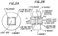
- the optical isolator comprises a polarizer 7, a 45 degree - Faraday rotator 9, an analyzer 10, and a magnet 4, wherein the polarizer 7 and the Faraday rotator 9 are fixed on their optic planes by use of a low melting point glass 8 surrounding an end portion 7a of the polarizer 7, and the Faraday rotator 9 and the analyzer 10 are also fixed on their optic planes by use of a low melting point glass 8 surrounding an end portion 10a of the analyzer 10, while the magnet 12 is fixed on an outer periphery of the polarizer 7, the Faraday rotator 9 and the analyzer 10 thus fixed by use of a low melting point glass 6.
- a polarization plane of the analyzer 10 is arranged to be rotated relative to that of the polarizer 7, and the 45 degree - Faraday rotator 9 is made of a thick film of (GdBi)3 Fe5O12 (Bi-substituted gadolinium iron garnet), a thick film of (GdBi)3 (FeAlGa)5O12 (Bi-substituted gadolinium iron aluminium gallium garnet), etc. obtained, for instance, by liquid phase epitaxy.
- (RBi) IG (Bi-substituted rare earth iron garnet) is large in Faraday rotation coefficient and small in saturation magnetization, so that a small sized optical isolator can be realized by use of it.
- an optical isolator having a diameter of 4mm and a length of 3mm is realized.
- the low melting point glass 6 has a melting point lower than that of the low melting point glass 8.
- the assembly of the polarizer 7, the 45 degree - Faraday rotator 9 and the analyzer 10 fixed beforehand and the magnet 12 is carried out at a temperature lower than the melting point of the low melting point glass 8 and higher than that of the low melting point glass 6. Under this process condition, the disassembling of the polarizer 7, the Faraday rotator 9 and the analyzer 10 is avoided.
- anti-reflection films for air are provided on light input and output planes of the polarizer 7, the 45 degree - Faraday rotator 9, and the analyzer 10.
- input light (solid line arrow) is supplied to the polarizer 7 of the optical isolator, so that output light (solid line arrow) having a polarization rotated relative to a polarization plane of the polarizer 7 by 45 degrees is supplied from the analyzer 10 of the optical isolator, in the same principle as explained in the conventional optical isolator.
- return light (dot line arrow) is interrupted not to be propagated through the optical isolator.
- a polarizer substrate having a plurality of polarizers 7 each defined by cutting lines 11 and having an end portion 7a, a 45 degree - Faraday rotator substrate having the plurality of 45 degree - Faraday rotators 9 each defined by cutting lines 11, and an analyzer substrate having the plurality of analyzers 10 each defined by cutting liens and having an end portion 10a are assembled by using first and second half-sintered grid shaped low melting point glass tablets 8A which are respectively interposed between the polarizer and Faraday rotator substrates and between the Faraday rotator and analyzer substrates, such that the end portions 7a and 10a of the polarizer and analyzer substrates are accommodated in openings of the grid shaped low melting point glass tablets 8A.
- the assembled structure is cut to be separated by the cutting lines 11.
- the analyzer 10 is fabricated in advance to have a polarization plane rotated relative to a polarization plane of the polarizer 7 by 45 degrees.
- the polarizer 7, the 45 degree - Faraday rotator 9 and the analyzer 10 are stacked, such that the analyzer 10 coincides in rotational direction of polarization plane with the 45 degree - Faraday rotator 9, and anti-reflection films for air are provided on facing optical planes of the polarizer 7, the 45 degree - Faraday rotator 9 and the analyzer 10.
- the polarizer substrate and the analyzer substrate have the end portions 7a and 10a which are defined by grid shaped grooves.
- the grooves are provided to correspond to the cutting lines 11 in accordance with the shaving by use of a precise blade saw having a thickness of less than 0.2mm.
- a depth of the grooves is smaller than a thickness of the grid shaped low melting point glass tablets 8A, so that the grid shaped low melting point glass tablets 8A are well contacted with the contacting portions of the polarizer, 45 degree - Faraday rotator and analyzer substrates.
- the depth of the grooves for defining the end portions 7a and 10a is 0.3mm, and the thickness of the glass tablets 8A is 0.35mm.
- a width of the grooves for defining the end portions 7a and 10a is determined dependent on the width W3 of frames of the glass tablets 8A.
- the glass tablets 8A are required to be handled in such a manner that the glass tablets 8A are not broken, when they are mounted on the analyzer substrate, and subsequently on the 45 degree - Faraday rotator substrate by means of an automatical assembling apparatus.
- Fig. 3C the aforementioned separated structure is obtained in accordance with the separation of the assembled structure along the cutting lines 11 positioned over the central lines of the frames of the glass tablets 8A by use of a blade having a thin width.
- optical isolator elements each having the polarizer 7, the 45 degree - Faraday rotator 9 and the analyzer 10 which are assembled by the low melting point glasses 8 fixed on the outer peripheries of the end portions 7a and 10a thereof between the polarizer and Faraday rotator substrates and between the Faraday rotator and analyzer substrates.
- a size of this optical isolator element is 1.7mm in side and 3mm in length.
- this optical isolator element is fixed on the central axis of the magnet 12 to the magnet 12 by use of a low melting point glass 6 (see Figs. 2A and 2B) applied between an outer periphery of the optical isolator element and an inner periphery of the magnet 12.
- the low melting point glass 6 has a melting point lower than that of the low melting point glass 8, as explained before.
- the optical isolator is fabricated, as shown in Figs. 2A and 2B.
- the 45 degree - Faraday rotator 9 may be provided with the end portions having concave peripheries for adhesive on the both sides thereof into which the low melting point glasses 8 are applied in place of the polarizer 7 and the analyzer 10. Further, the dimensions as described before may be changed dependent on the design of an optical isolator.
- low melting point glass tablet 8A may be replaced by low melting point glass filled into grooves for defining the end portions of the polarizer 7 and the analyzer 10.
Landscapes
- Physics & Mathematics (AREA)
- Nonlinear Science (AREA)
- Engineering & Computer Science (AREA)
- Power Engineering (AREA)
- General Physics & Mathematics (AREA)
- Optics & Photonics (AREA)
Applications Claiming Priority (2)
| Application Number | Priority Date | Filing Date | Title |
|---|---|---|---|
| JP3105842A JP2697354B2 (ja) | 1991-05-10 | 1991-05-10 | 光アイソレータの製造方法 |
| JP105842/91 | 1991-05-10 |
Publications (3)
| Publication Number | Publication Date |
|---|---|
| EP0512572A2 true EP0512572A2 (de) | 1992-11-11 |
| EP0512572A3 EP0512572A3 (en) | 1993-03-24 |
| EP0512572B1 EP0512572B1 (de) | 1995-12-27 |
Family
ID=14418275
Family Applications (1)
| Application Number | Title | Priority Date | Filing Date |
|---|---|---|---|
| EP92107893A Expired - Lifetime EP0512572B1 (de) | 1991-05-10 | 1992-05-11 | Optischer Isolator und Verfahren zu seiner Herstellung |
Country Status (4)
| Country | Link |
|---|---|
| US (1) | US5305137A (de) |
| EP (1) | EP0512572B1 (de) |
| JP (1) | JP2697354B2 (de) |
| DE (1) | DE69207059T2 (de) |
Cited By (4)
| Publication number | Priority date | Publication date | Assignee | Title |
|---|---|---|---|---|
| EP0615145A1 (de) * | 1993-03-10 | 1994-09-14 | Tokin Corporation | Anordnung eines optischen Isolators, welche die Verkippung der optischen Achse aufgrund von Klebstoff-Verformung verhindert |
| EP0785456A1 (de) * | 1996-01-17 | 1997-07-23 | Hewlett-Packard Company | Optischer Isolator |
| EP0747747B1 (de) * | 1994-12-27 | 1998-06-17 | Tokin Corporation | Verfahren zur herstellung einer optischen anordnung für optischen isolator |
| EP0860731A1 (de) * | 1997-02-25 | 1998-08-26 | Hewlett-Packard Company | Kompakter Drei-Tor-Zirkulator mit geringem Übersprechen |
Families Citing this family (16)
| Publication number | Priority date | Publication date | Assignee | Title |
|---|---|---|---|---|
| JPH06265726A (ja) * | 1993-03-15 | 1994-09-22 | Chichibu Cement Co Ltd | 偏光子の接合方法およびメタライズ方法 |
| US5867314A (en) * | 1993-12-09 | 1999-02-02 | Fuji Electrochemical Co., Ltd. | Structure of optical passive device and assembling method therefor |
| US5657151A (en) * | 1993-12-09 | 1997-08-12 | Lucent Technologies Inc. | Polarization scrambler/modulator |
| TW294810B (de) * | 1994-09-23 | 1997-01-01 | Philips Electronics Nv | |
| US5539574A (en) * | 1994-12-21 | 1996-07-23 | At&T Corp. | Optical isolator with fabry-perot ripple reduction |
| EP0757275A1 (de) * | 1995-02-16 | 1997-02-05 | Tokin Corporation | Optischer isolator |
| DE19506498C2 (de) * | 1995-02-24 | 1999-07-22 | Gsaenger Optoelektronik Gmbh & | Faraday-Isolator |
| US6043933A (en) * | 1997-11-21 | 2000-03-28 | Hewlett-Packard Company | Split optical element and a low cost fabrication approach |
| US6126775A (en) * | 1998-02-06 | 2000-10-03 | Horizon Photonics, Llc | Method of microfabrication |
| US6395126B1 (en) | 1998-02-06 | 2002-05-28 | Horizon Photonics, Inc. | Method of micro-fabrication |
| JP4550209B2 (ja) * | 2000-03-08 | 2010-09-22 | 信越化学工業株式会社 | 光アイソレータ |
| US20020154403A1 (en) * | 2001-04-23 | 2002-10-24 | Trotter, Donald M. | Photonic crystal optical isolator |
| JP2006309190A (ja) * | 2005-03-30 | 2006-11-09 | Kyocera Corp | 光アイソレータおよびそれを用いた光モジュール |
| DE102005040408B4 (de) | 2005-08-26 | 2010-08-26 | Rheinmetall Defence Electronics Gmbh | Skalierbares Frachtladesystem, insbesondere für ein Luftfahrzeug |
| JP5528827B2 (ja) * | 2010-01-25 | 2014-06-25 | 信越化学工業株式会社 | 光アイソレータ |
| JP5848474B1 (ja) * | 2015-03-17 | 2016-01-27 | 株式会社精工技研 | 光学部品の製造方法 |
Family Cites Families (10)
| Publication number | Priority date | Publication date | Assignee | Title |
|---|---|---|---|---|
| JPS59176721A (ja) * | 1983-03-25 | 1984-10-06 | Fujitsu Ltd | 光アイソレ−タ |
| US4686678A (en) * | 1984-03-27 | 1987-08-11 | Nec Corporation | Semiconductor laser apparatus with isolator |
| JPS61266485A (ja) * | 1985-05-21 | 1986-11-26 | Sharp Corp | 溶着方法 |
| JPS62148918A (ja) * | 1985-12-23 | 1987-07-02 | Matsushita Electric Ind Co Ltd | 光アイソレ−タ装置 |
| JPH0750262B2 (ja) * | 1988-02-04 | 1995-05-31 | 富士電気化学株式会社 | 光アイソレータの製造方法 |
| GB2217508B (en) * | 1988-03-29 | 1992-08-19 | Hitachi Metals Ltd | Flying-type magnetic head |
| JP2645862B2 (ja) * | 1988-08-11 | 1997-08-25 | 株式会社日立製作所 | 半導体発光装置およびその応用製品 |
| JPH02123321A (ja) * | 1988-11-02 | 1990-05-10 | Shojiro Kawakami | 光アイソレータの製造方法および同製造方法に用いられる偏光素子アレイ並びに同製造方法で得られた光アイソレータを一体化した光学モジュール |
| JP2758693B2 (ja) * | 1990-04-18 | 1998-05-28 | 信越化学工業株式会社 | 光アイソレータおよびその製造方法 |
| JP2628774B2 (ja) * | 1990-04-20 | 1997-07-09 | 株式会社日立製作所 | 光アイソレータ内蔵形半導体レーザモジュール |
-
1991
- 1991-05-10 JP JP3105842A patent/JP2697354B2/ja not_active Expired - Lifetime
-
1992
- 1992-05-11 DE DE69207059T patent/DE69207059T2/de not_active Expired - Fee Related
- 1992-05-11 EP EP92107893A patent/EP0512572B1/de not_active Expired - Lifetime
- 1992-05-11 US US07/881,257 patent/US5305137A/en not_active Expired - Fee Related
Cited By (6)
| Publication number | Priority date | Publication date | Assignee | Title |
|---|---|---|---|---|
| EP0615145A1 (de) * | 1993-03-10 | 1994-09-14 | Tokin Corporation | Anordnung eines optischen Isolators, welche die Verkippung der optischen Achse aufgrund von Klebstoff-Verformung verhindert |
| EP0747747B1 (de) * | 1994-12-27 | 1998-06-17 | Tokin Corporation | Verfahren zur herstellung einer optischen anordnung für optischen isolator |
| EP0785456A1 (de) * | 1996-01-17 | 1997-07-23 | Hewlett-Packard Company | Optischer Isolator |
| US5808793A (en) * | 1996-01-17 | 1998-09-15 | Hewlett-Packard Company | Low-cost compact optical isolators |
| EP0860731A1 (de) * | 1997-02-25 | 1998-08-26 | Hewlett-Packard Company | Kompakter Drei-Tor-Zirkulator mit geringem Übersprechen |
| US6026202A (en) * | 1997-02-25 | 2000-02-15 | Hewlett-Packard Company | Compact, low crosstalk, three-port optical circulator |
Also Published As
| Publication number | Publication date |
|---|---|
| JP2697354B2 (ja) | 1998-01-14 |
| EP0512572A3 (en) | 1993-03-24 |
| DE69207059D1 (de) | 1996-02-08 |
| US5305137A (en) | 1994-04-19 |
| EP0512572B1 (de) | 1995-12-27 |
| DE69207059T2 (de) | 1996-05-15 |
| JPH04333818A (ja) | 1992-11-20 |
Similar Documents
| Publication | Publication Date | Title |
|---|---|---|
| EP0512572B1 (de) | Optischer Isolator und Verfahren zu seiner Herstellung | |
| EP0525208B1 (de) | Optischer isolator | |
| EP0785456B1 (de) | Herstellung optischer Isolatoren | |
| US6275336B1 (en) | Optical isolator | |
| KR100287596B1 (ko) | 광아이솔레이터 | |
| EP0707230B1 (de) | Optischer Isolator | |
| JP2542532B2 (ja) | 偏光無依存型光アイソレ―タの製造方法 | |
| EP1396751B1 (de) | Kombinierter optischer variabler Abschwächer und Isolator, und Montageverfahren | |
| JP3290474B2 (ja) | 半導体レーザアレイ用光アイソレータ | |
| JP3739686B2 (ja) | 埋込型光アイソレータ | |
| JP3075435B2 (ja) | 光アイソレータ | |
| JP4540155B2 (ja) | 光アイソレータ | |
| JPH10142558A (ja) | 光アイソレータおよびその製造方法 | |
| JPH05323234A (ja) | 3ポート型光サーキュレータ | |
| JPH02188715A (ja) | 光アイソレータ | |
| JP2598531Y2 (ja) | 光アイソレータ | |
| JPH04264515A (ja) | 光アイソレータ | |
| JP2775499B2 (ja) | 光アイソレータ | |
| WO2000049450A2 (en) | Optical circulator | |
| JP2003329975A (ja) | 光デバイスとその製造方法 | |
| WO2000049450A9 (en) | Optical circulator | |
| JPH03107915A (ja) | 光アイソレータ | |
| JPH0749468A (ja) | 光アイソレータ | |
| JPH03137615A (ja) | 光アイソレータの製造方法 | |
| JP2970159B2 (ja) | 光アイソレータ及びその製造方法 |
Legal Events
| Date | Code | Title | Description |
|---|---|---|---|
| PUAI | Public reference made under article 153(3) epc to a published international application that has entered the european phase |
Free format text: ORIGINAL CODE: 0009012 |
|
| AK | Designated contracting states |
Kind code of ref document: A2 Designated state(s): DE FR GB |
|
| PUAL | Search report despatched |
Free format text: ORIGINAL CODE: 0009013 |
|
| AK | Designated contracting states |
Kind code of ref document: A3 Designated state(s): DE FR GB |
|
| 17P | Request for examination filed |
Effective date: 19930217 |
|
| 17Q | First examination report despatched |
Effective date: 19950113 |
|
| GRAA | (expected) grant |
Free format text: ORIGINAL CODE: 0009210 |
|
| AK | Designated contracting states |
Kind code of ref document: B1 Designated state(s): DE FR GB |
|
| REF | Corresponds to: |
Ref document number: 69207059 Country of ref document: DE Date of ref document: 19960208 |
|
| ET | Fr: translation filed | ||
| PLBE | No opposition filed within time limit |
Free format text: ORIGINAL CODE: 0009261 |
|
| STAA | Information on the status of an ep patent application or granted ep patent |
Free format text: STATUS: NO OPPOSITION FILED WITHIN TIME LIMIT |
|
| 26N | No opposition filed | ||
| PGFP | Annual fee paid to national office [announced via postgrant information from national office to epo] |
Ref country code: DE Payment date: 20010508 Year of fee payment: 10 |
|
| PGFP | Annual fee paid to national office [announced via postgrant information from national office to epo] |
Ref country code: GB Payment date: 20010509 Year of fee payment: 10 |
|
| PGFP | Annual fee paid to national office [announced via postgrant information from national office to epo] |
Ref country code: FR Payment date: 20010518 Year of fee payment: 10 |
|
| REG | Reference to a national code |
Ref country code: GB Ref legal event code: IF02 |
|
| PG25 | Lapsed in a contracting state [announced via postgrant information from national office to epo] |
Ref country code: GB Free format text: LAPSE BECAUSE OF NON-PAYMENT OF DUE FEES Effective date: 20020511 |
|
| PG25 | Lapsed in a contracting state [announced via postgrant information from national office to epo] |
Ref country code: DE Free format text: LAPSE BECAUSE OF NON-PAYMENT OF DUE FEES Effective date: 20021203 |
|
| GBPC | Gb: european patent ceased through non-payment of renewal fee |
Effective date: 20020511 |
|
| PG25 | Lapsed in a contracting state [announced via postgrant information from national office to epo] |
Ref country code: FR Free format text: LAPSE BECAUSE OF NON-PAYMENT OF DUE FEES Effective date: 20030131 |
|
| REG | Reference to a national code |
Ref country code: FR Ref legal event code: ST |