EP0512711A2 - Dispositf de mesure de la quantité d'électricité stockée dans une batterie - Google Patents
Dispositf de mesure de la quantité d'électricité stockée dans une batterie Download PDFInfo
- Publication number
- EP0512711A2 EP0512711A2 EP92303578A EP92303578A EP0512711A2 EP 0512711 A2 EP0512711 A2 EP 0512711A2 EP 92303578 A EP92303578 A EP 92303578A EP 92303578 A EP92303578 A EP 92303578A EP 0512711 A2 EP0512711 A2 EP 0512711A2
- Authority
- EP
- European Patent Office
- Prior art keywords
- battery
- electricity
- measuring device
- voltage
- communication apparatus
- Prior art date
- Legal status (The legal status is an assumption and is not a legal conclusion. Google has not performed a legal analysis and makes no representation as to the accuracy of the status listed.)
- Granted
Links
Images

Classifications
-
- G—PHYSICS
- G01—MEASURING; TESTING
- G01R—MEASURING ELECTRIC VARIABLES; MEASURING MAGNETIC VARIABLES
- G01R31/00—Arrangements for testing electric properties; Arrangements for locating electric faults; Arrangements for electrical testing characterised by what is being tested not provided for elsewhere
- G01R31/36—Arrangements for testing, measuring or monitoring the electrical condition of accumulators or electric batteries, e.g. capacity or state of charge [SoC]
- G01R31/382—Arrangements for monitoring battery or accumulator variables, e.g. SoC
- G01R31/3835—Arrangements for monitoring battery or accumulator variables, e.g. SoC involving only voltage measurements
-
- G—PHYSICS
- G01—MEASURING; TESTING
- G01R—MEASURING ELECTRIC VARIABLES; MEASURING MAGNETIC VARIABLES
- G01R31/00—Arrangements for testing electric properties; Arrangements for locating electric faults; Arrangements for electrical testing characterised by what is being tested not provided for elsewhere
- G01R31/36—Arrangements for testing, measuring or monitoring the electrical condition of accumulators or electric batteries, e.g. capacity or state of charge [SoC]
- G01R31/3644—Constructional arrangements
- G01R31/3648—Constructional arrangements comprising digital calculation means, e.g. for performing an algorithm
Definitions
- This invention relates to a device which is equipped in such a radio communication apparatus as a time-division-multiplex mobile transceiver, portable telephone unit or indoor wireless telephone unit and is intended to measure the quantity of electricity stored in the battery used in the apparatus thereby to indicate the quantity of consumed electricity after the battery has been charged.
- Fig. 4 shows the arrangement of a conventional device for measuring the quantity of battery electricity.
- indicated by 2 is a voltage detection circuit which detects the voltage of a battery 1 and delivers the voltage level to an A/D converter 3.
- Output data of the A/D converter 3 is fed to a digital display panel 4, and it calculates the quantity of electricity of the battery 1 based on the characteristics of the battery, i.e., the relation between the quantity of electricity and the output voltage, and displays the result.
- the A/D converter 3 is capable of displaying the quantity of battery electricity consumed by a time-division-multiplex transceiver 5.
- the conventional battery electricity measuring device shown in Fig. 4 needs to measure a pulsative battery voltage resulting from pulsative power consumption by the time-division-multiplex transceiver 5, and therefore it is deficient in the accuracy of measurement.
- a digital automobile telephone unit has its transmission power output varied in response to the radio signal from the base station, and such a varying pulsative battery voltage makes the electricity measurement more difficult.
- An object of this invention is to provide a device capable of accurately measuring the quantity of battery electricity through the synchronization of operation of the A/D converter with the time-division-multiplex control signal provided by the time-division-multiplex transceiver.
- the electricity measuring device based on this invention is designed to calculate the quantity of battery electricity by detecting the battery voltage during the inactive period of transmission and reception of the unit. In consequence, a stable battery voltage is detected, and the quantity of battery electricity can be measured accurately.
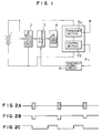
- Fig. 1 shows the battery electricity measuring device based on this invention.
- a battery 2 is a voltage detection circuit for detecting the output voltage of the battery 1
- 3 is an A/D converter
- 4 is a digital display panel
- 5 is a time-division-multiplex transceiver which operates on the battery 1
- 6 is a synchronizing circuit.
- the transceiver 5 consists of a transceiver section 5a and a control section 5b which controls the transceiver section 5a.
- the transceiver 5 produces a timing signal 7 for the time-division-multiplex transmission control, and the signal is fed to the synchronizing circuit 6 so that the output of the circuit 6 controls the timing of sampling of the battery voltage by the A/D converter 3.
- the time-division-multiplex transceiver has intermittent transmission outputs as shown by Fig. 2A.
- This load variation causes the battery output voltage to pulsate as shown by Fig. 2B.
- the transmitting operation takes place in response to the command from the time-division-multiplex controller 5b in the transceiver 5, and the A/D converter 3 is designed to sample the battery voltage when transmission output is off by being timed to the timing signal 7 provided by the time-division-multiplex controller.
- the timing signal 7 is applied to the synchronizing circuit 6 so that the A/D converter 3 operates at the rising edge of the output pulse signal as shown by Fig. 2C. Consequently, according to this invention, the A/D converter 3 detects the battery voltage during the period when it is stable because of little power consumption of the battery 1, and the detection result is accurate enough to calculate the quantity of electricity of the battery 1.
- time-division-multiplex transceivers base their time-division-multiplex control on the microcomputer incorporated in the transceiver 5, and the timing signal 7 used for this control is produced by means of programming.
- the digital display panel 4 which functions to calculate the quantity of electricity of the battery 1 from the battery voltage, is mainly controlled by the microcomputer. It is also possible for this invention to use a single microcomputer and associated program for synchronizing the detection of battery voltage with the time-division-multiplex control.
- Resulting data based on the accurate detection is used by the digital display panel 4 for displaying the residual electricity of the battery at a resolution of five levels for example, or indicating the alarm of too-low battery voltage.
- Fig. 3 shows another embodiment of this invention.
- the time-division-multiplex transceiver 5 shown in Fig. 1 is divided into a time-division-multiplex controller 8 and a transceiver section 9, and the synchronizing circuit 6 and digital display panel 4 in Fig. 1 are replaced with a microcomputer 10 and a display panel 11.
- the arrangement of Fig. 3 operates such that the time-division-multiplex controller 8 controls the operational timing of the transceiver section 9 and imparts the timing of transmission to the microcomputer 10.
- the microcomputer 10 imparts the timing of operation to the A/D converter 3, which then returns the voltage data to the microcomputer 10, and it calculates the quantity of battery electricity from the data.
- the result of calculation of the microcomputer 10 is displayed on the display panel 11.
- time-division-multiplex controller 8 and microcomputer 10 it is possible for the time-division-multiplex controller 8 and microcomputer 10 to be replaced with a single control microcomputer.
- the present invention is also applicable to mobile transceivers of the press-and-talk design, besides the foregoing time-division-multiplex mobile transceivers.
- the time-division-multiplex transceiver is provided with the function of measuring the quantity of battery electricity in synchronism with the time-division-multiplex control of the unit, and consequently the quantity of residual electricity of the built-in battery can be measured and displayed accurately.
Landscapes
- Physics & Mathematics (AREA)
- General Physics & Mathematics (AREA)
- Tests Of Electric Status Of Batteries (AREA)
- Measurement Of Current Or Voltage (AREA)
- Charge And Discharge Circuits For Batteries Or The Like (AREA)
- Monitoring And Testing Of Transmission In General (AREA)
- Mobile Radio Communication Systems (AREA)
- Transceivers (AREA)
Applications Claiming Priority (3)
| Application Number | Priority Date | Filing Date | Title |
|---|---|---|---|
| JP3101299A JP2616509B2 (ja) | 1991-05-07 | 1991-05-07 | 電気量測定装置 |
| JP101299/91 | 1991-05-07 | ||
| JP10129991 | 1991-05-07 |
Publications (3)
| Publication Number | Publication Date |
|---|---|
| EP0512711A2 true EP0512711A2 (fr) | 1992-11-11 |
| EP0512711A3 EP0512711A3 (en) | 1993-09-15 |
| EP0512711B1 EP0512711B1 (fr) | 1999-07-07 |
Family
ID=14296944
Family Applications (1)
| Application Number | Title | Priority Date | Filing Date |
|---|---|---|---|
| EP92303578A Expired - Lifetime EP0512711B1 (fr) | 1991-05-07 | 1992-04-22 | Dispositif de mesure de la quantité d'électricité stockée dans une batterie |
Country Status (3)
| Country | Link |
|---|---|
| EP (1) | EP0512711B1 (fr) |
| JP (1) | JP2616509B2 (fr) |
| DE (1) | DE69229522T2 (fr) |
Cited By (7)
| Publication number | Priority date | Publication date | Assignee | Title |
|---|---|---|---|---|
| EP0608086A3 (fr) * | 1993-01-21 | 1994-12-07 | Toshiba Kk | Indicateur de l'état de charge d'une batterie pour un émetteur-récepteur. |
| EP0665444A1 (fr) * | 1994-01-31 | 1995-08-02 | Nec Corporation | Détecteur de capacité d'une batterie |
| US5784690A (en) * | 1994-01-21 | 1998-07-21 | Kabushiki Kaisha Toshiba | Transceiver measuring battery voltage when receiving in a TDMA system |
| US6810338B2 (en) | 2000-10-23 | 2004-10-26 | Telefonaktiebolaget Lm Ericsson (Publ) | Monitoring circuit |
| CN102520364A (zh) * | 2011-12-20 | 2012-06-27 | 广东欧珀移动通信有限公司 | 一种利用电池电压显示电量的方法 |
| CN103176132A (zh) * | 2011-12-22 | 2013-06-26 | 联芯科技有限公司 | 电池电量的估算方法及终端设备 |
| WO2015154381A1 (fr) * | 2014-08-08 | 2015-10-15 | 中兴通讯股份有限公司 | Procédé et système de détection de niveau de charge de batterie et batterie |
Families Citing this family (4)
| Publication number | Priority date | Publication date | Assignee | Title |
|---|---|---|---|---|
| JP2739845B2 (ja) * | 1995-07-21 | 1998-04-15 | 日本電気株式会社 | 電源電圧検出機能付無線選択呼出受信機 |
| JP4536569B2 (ja) * | 2005-04-01 | 2010-09-01 | リンナイ株式会社 | 電池電圧監視方法 |
| JP2017022613A (ja) * | 2015-07-13 | 2017-01-26 | パナソニックIpマネジメント株式会社 | 通信装置、通信システムおよびプログラム |
| CN115707985B (zh) * | 2021-08-19 | 2024-03-22 | 北京大瞬科技有限公司 | 计算电池电量的方法及电池管理系统 |
Family Cites Families (4)
| Publication number | Priority date | Publication date | Assignee | Title |
|---|---|---|---|---|
| JPS55136818A (en) * | 1979-04-11 | 1980-10-25 | Nippon Electric Co | Power voltage drop detecting circuit |
| CH642808B (fr) * | 1981-01-05 | 1900-01-01 | Rolex Montres | Procede pour determiner l'etat de decharge d'une pile electrique et dispositif pour la mise en oeuvre de ce procede. |
| JPS6213046U (fr) * | 1985-07-08 | 1987-01-26 | ||
| JPH04110785A (ja) * | 1990-08-31 | 1992-04-13 | Fujitsu Ltd | バッテリのアラーム装置 |
-
1991
- 1991-05-07 JP JP3101299A patent/JP2616509B2/ja not_active Expired - Lifetime
-
1992
- 1992-04-22 EP EP92303578A patent/EP0512711B1/fr not_active Expired - Lifetime
- 1992-04-22 DE DE69229522T patent/DE69229522T2/de not_active Expired - Lifetime
Cited By (10)
| Publication number | Priority date | Publication date | Assignee | Title |
|---|---|---|---|---|
| EP0608086A3 (fr) * | 1993-01-21 | 1994-12-07 | Toshiba Kk | Indicateur de l'état de charge d'une batterie pour un émetteur-récepteur. |
| US5613227A (en) * | 1993-01-21 | 1997-03-18 | Kabushiki Kaisha Toshiba | Transceiver measuring battery voltage when not transmitting in a TDMA system |
| US5784690A (en) * | 1994-01-21 | 1998-07-21 | Kabushiki Kaisha Toshiba | Transceiver measuring battery voltage when receiving in a TDMA system |
| EP0665444A1 (fr) * | 1994-01-31 | 1995-08-02 | Nec Corporation | Détecteur de capacité d'une batterie |
| US5610525A (en) * | 1994-01-31 | 1997-03-11 | Nec Corporation | Battery capacity detector |
| US6810338B2 (en) | 2000-10-23 | 2004-10-26 | Telefonaktiebolaget Lm Ericsson (Publ) | Monitoring circuit |
| CN102520364A (zh) * | 2011-12-20 | 2012-06-27 | 广东欧珀移动通信有限公司 | 一种利用电池电压显示电量的方法 |
| CN103176132A (zh) * | 2011-12-22 | 2013-06-26 | 联芯科技有限公司 | 电池电量的估算方法及终端设备 |
| CN103176132B (zh) * | 2011-12-22 | 2015-08-12 | 联芯科技有限公司 | 电池电量的估算方法及终端设备 |
| WO2015154381A1 (fr) * | 2014-08-08 | 2015-10-15 | 中兴通讯股份有限公司 | Procédé et système de détection de niveau de charge de batterie et batterie |
Also Published As
| Publication number | Publication date |
|---|---|
| DE69229522D1 (de) | 1999-08-12 |
| JP2616509B2 (ja) | 1997-06-04 |
| EP0512711A3 (en) | 1993-09-15 |
| EP0512711B1 (fr) | 1999-07-07 |
| JPH04331518A (ja) | 1992-11-19 |
| DE69229522T2 (de) | 1999-10-28 |
Similar Documents
| Publication | Publication Date | Title |
|---|---|---|
| US5953677A (en) | Mobile telephone apparatus with power saving | |
| EP0512711A2 (fr) | Dispositf de mesure de la quantité d'électricité stockée dans une batterie | |
| US12422305B2 (en) | Wireless meat temperature probe | |
| US20100072974A1 (en) | Electronic apparatus | |
| JP2001103671A (ja) | 電話機用電池残量表示装置 | |
| EP3432090B1 (fr) | Montre électronique et système de commande de communication | |
| US6950683B2 (en) | Battery life indication | |
| GB2227323A (en) | Electronic level indicator | |
| KR100238529B1 (ko) | 시분할 무선단말기의 배터리 전압 표시 방법 | |
| CN213274689U (zh) | 一种具有图像识别功能的标准压力校验台 | |
| JP2859312B2 (ja) | 無線式液量測定装置 | |
| JP3459511B2 (ja) | 通信機器用電池残量表示器 | |
| CN221804162U (zh) | 一种无线充电效率测试系统 | |
| JP2591801Y2 (ja) | 携帯型振動表示器 | |
| JPH0832506A (ja) | 電気量測定装置 | |
| JPS6243504B2 (fr) | ||
| JPH02176527A (ja) | 無線式液位信号送信装置 | |
| JPH09266072A (ja) | 自動調光制御システム | |
| TW348345B (en) | A paging receiver with receive signal strength indicator | |
| JP2000304779A (ja) | 電力変換装置 | |
| JP2784021B2 (ja) | 無線式液量測定装置 | |
| KR20040033537A (ko) | 지에스엠 방식 이동통신 단말기의 배터리 잔량 표시 회로 | |
| JPS633324A (ja) | 太陽電池による電源システム | |
| CN121115444A (zh) | 一种电能表的时钟检测方法、测试设备以及电子设备 | |
| JPH0426076A (ja) | 試験用電源装置 |
Legal Events
| Date | Code | Title | Description |
|---|---|---|---|
| PUAI | Public reference made under article 153(3) epc to a published international application that has entered the european phase |
Free format text: ORIGINAL CODE: 0009012 |
|
| AK | Designated contracting states |
Kind code of ref document: A2 Designated state(s): DE FR GB |
|
| PUAL | Search report despatched |
Free format text: ORIGINAL CODE: 0009013 |
|
| AK | Designated contracting states |
Kind code of ref document: A3 Designated state(s): DE FR GB |
|
| 17P | Request for examination filed |
Effective date: 19931103 |
|
| 17Q | First examination report despatched |
Effective date: 19960311 |
|
| GRAG | Despatch of communication of intention to grant |
Free format text: ORIGINAL CODE: EPIDOS AGRA |
|
| GRAG | Despatch of communication of intention to grant |
Free format text: ORIGINAL CODE: EPIDOS AGRA |
|
| GRAH | Despatch of communication of intention to grant a patent |
Free format text: ORIGINAL CODE: EPIDOS IGRA |
|
| GRAH | Despatch of communication of intention to grant a patent |
Free format text: ORIGINAL CODE: EPIDOS IGRA |
|
| GRAA | (expected) grant |
Free format text: ORIGINAL CODE: 0009210 |
|
| AK | Designated contracting states |
Kind code of ref document: B1 Designated state(s): DE FR GB |
|
| REF | Corresponds to: |
Ref document number: 69229522 Country of ref document: DE Date of ref document: 19990812 |
|
| ET | Fr: translation filed | ||
| PLBE | No opposition filed within time limit |
Free format text: ORIGINAL CODE: 0009261 |
|
| STAA | Information on the status of an ep patent application or granted ep patent |
Free format text: STATUS: NO OPPOSITION FILED WITHIN TIME LIMIT |
|
| 26N | No opposition filed | ||
| REG | Reference to a national code |
Ref country code: GB Ref legal event code: IF02 |
|
| PGFP | Annual fee paid to national office [announced via postgrant information from national office to epo] |
Ref country code: FR Payment date: 20110426 Year of fee payment: 20 Ref country code: DE Payment date: 20110420 Year of fee payment: 20 |
|
| PGFP | Annual fee paid to national office [announced via postgrant information from national office to epo] |
Ref country code: GB Payment date: 20110420 Year of fee payment: 20 |
|
| REG | Reference to a national code |
Ref country code: DE Ref legal event code: R071 Ref document number: 69229522 Country of ref document: DE |
|
| REG | Reference to a national code |
Ref country code: DE Ref legal event code: R071 Ref document number: 69229522 Country of ref document: DE |
|
| REG | Reference to a national code |
Ref country code: GB Ref legal event code: PE20 Expiry date: 20120421 |
|
| PG25 | Lapsed in a contracting state [announced via postgrant information from national office to epo] |
Ref country code: DE Free format text: LAPSE BECAUSE OF EXPIRATION OF PROTECTION Effective date: 20120423 |
|
| PG25 | Lapsed in a contracting state [announced via postgrant information from national office to epo] |
Ref country code: GB Free format text: LAPSE BECAUSE OF EXPIRATION OF PROTECTION Effective date: 20120421 |