EP0512757A2 - Dispositif pour la finition d'une surface sensiblement conique - Google Patents
Dispositif pour la finition d'une surface sensiblement conique Download PDFInfo
- Publication number
- EP0512757A2 EP0512757A2 EP92303937A EP92303937A EP0512757A2 EP 0512757 A2 EP0512757 A2 EP 0512757A2 EP 92303937 A EP92303937 A EP 92303937A EP 92303937 A EP92303937 A EP 92303937A EP 0512757 A2 EP0512757 A2 EP 0512757A2
- Authority
- EP
- European Patent Office
- Prior art keywords
- cone
- finishing
- axis
- rigid members
- members
- Prior art date
- Legal status (The legal status is an assumption and is not a legal conclusion. Google has not performed a legal analysis and makes no representation as to the accuracy of the status listed.)
- Granted
Links
- 239000000463 material Substances 0.000 description 8
- 230000003287 optical effect Effects 0.000 description 5
- 238000009304 pastoral farming Methods 0.000 description 3
- 238000005498 polishing Methods 0.000 description 2
- 239000004593 Epoxy Substances 0.000 description 1
- 150000001875 compounds Chemical class 0.000 description 1
- 230000001419 dependent effect Effects 0.000 description 1
- 238000007730 finishing process Methods 0.000 description 1
- 229910052751 metal Inorganic materials 0.000 description 1
- 239000002184 metal Substances 0.000 description 1
- 150000002739 metals Chemical class 0.000 description 1
- 229920003023 plastic Polymers 0.000 description 1
- 239000004033 plastic Substances 0.000 description 1
- 230000005855 radiation Effects 0.000 description 1
- 238000002310 reflectometry Methods 0.000 description 1
- 239000002002 slurry Substances 0.000 description 1
- 230000003595 spectral effect Effects 0.000 description 1
- 238000001228 spectrum Methods 0.000 description 1
Images

Classifications
-
- B—PERFORMING OPERATIONS; TRANSPORTING
- B24—GRINDING; POLISHING
- B24B—MACHINES, DEVICES, OR PROCESSES FOR GRINDING OR POLISHING; DRESSING OR CONDITIONING OF ABRADING SURFACES; FEEDING OF GRINDING, POLISHING, OR LAPPING AGENTS
- B24B33/00—Honing machines or devices; Accessories therefor
- B24B33/02—Honing machines or devices; Accessories therefor designed for working internal surfaces of revolution, e.g. of cylindrical or conical shapes
- B24B33/025—Internal surface of conical shape
-
- B—PERFORMING OPERATIONS; TRANSPORTING
- B24—GRINDING; POLISHING
- B24B—MACHINES, DEVICES, OR PROCESSES FOR GRINDING OR POLISHING; DRESSING OR CONDITIONING OF ABRADING SURFACES; FEEDING OF GRINDING, POLISHING, OR LAPPING AGENTS
- B24B13/00—Machines or devices designed for grinding or polishing optical surfaces on lenses or surfaces of similar shape on other work; Accessories therefor
- B24B13/015—Machines or devices designed for grinding or polishing optical surfaces on lenses or surfaces of similar shape on other work; Accessories therefor of television picture tube viewing panels, headlight reflectors or the like
Definitions
- the present invention generally relates to an apparatus for finishing a cone-like surface and, in particular, relates to one such apparatus having rigid members defining planes that, intersect in a line collinear with the axis of the cone-like surface.
- One particularly efficient surface commonly used for grazing incidence optical systems is a cone-like surface having a longitudinal axis.
- One major difficulty of fabricating such a surface is the efficient grinding and polishing, i.e., finishing, thereof.
- a typical finishing tool is a substantially rigid rectangular block of material having a contact face that is curved to approximate the shape of the cone-like surface.
- Such a tool is quite inefficient because a cone-like surface has both a longitudinally changing radius of curvature and a transversely changing radius of curvature. Such compound changes of radii of curvature prevent the efficient rotation of such a tool against the optical surface during finishing. Further, if such a tool is moved longitudinally, or parallel, to the optical axis, the change of radius of curvature causes a misfit between the tool and the surface being finished.
- this object is accomplished, at least in part, by an apparatus having rigid members affixed to a flexible finishing member and disposed such that the planes defined by the rigid members intersect in a line coincident with the longitudinal axis of the cone-like surface.
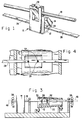
- An apparatus for finishing a cone-like surface includes a flexible base member 12 having first and second rigid members, 14 and 16, respectively, affixed thereto.
- the apparatus 10 further includes means 18 for retaining the first and second rigid members such that the planes defined thereby intersect collinearly with the axis 20 of the cone-like surface 22, shown in FIGURE 2, to be finished.
- the apparatus 10 can further include at least one pin member 24 disposed to engage a translation member 26, shown in FIGURES 3, 4 and 5. As more fully discussed hereinafter the pin member 24, serves to permit movement of the base member 12 transverse to the translation member 26 during operation.
- the base member 12 is generally trapezoidal in its planar unflexed state having the parallel sides thereof of such length as to match the change of radius of the cone-like surface 22 to be finished.
- the base member 12 may be generally triangular in its planar unflexed state.
- the first and second rigid members, 14 and 16, respectively, are affixed to the base member 12 and, in one embodiment, include slots 28 extending thereinto to enable engagement with an axial member 30.
- first and second rigid members, 14 and 16 respectively, each include a plurality of finger members that are disposed on opposing sides or side edges of the base member 12 such that they are interdigitated when the base member 12 is flexed to have the planes defined thereby intersect in a line that is collinear with the axis of the cone-like surface 22.
- the flexible base member 12 can be fabricated from commercially available flexible materials and is, for example, on the order of about 1/8 to 1/2 inches thick. In conjunction with the inherent material properties the flexibility of the apparatus 10 is determined by the thickness of the material. Typically, the larger the surface area desired for the base member 12 the thinner the base member 12 will be made.
- the first and second rigid members, 14 and 16, respectively, can be commercially available materials, including metals and plastics affixed to the base member 12 by either epoxy or screws or such other means as desired.
- the means 18 includes the axial member 30 disposed in and positioned by first and second axial member supports, 34 and 36 respectively, disposed on a platform 38.
- the cone-like optic 22 is, in one embodiment, disposed on first and second pairs of rollers, 40 and 42, respectively.
- the pairs of rollers, 40 and 42 both support and rotate the cone-like optic 22 being finished.
- the pairs of rollers, 40 and 42 are rotatably connected to a drive means 45.
- the pairs of rollers, 40 and 42 are mounted on roller mount members 44 having heights adapted to the cone-like optic 22 being finished to ensure that the center line 20, i.e., the axis of rotation, thereof is substantially parallel to the plane of the platform 38.
- the axial member 30 is disposed along the axis 20 of the cone-like optic 22 being finished and the apparatus 10 is disposed within the optic 22 with the first and second rigid members, 14 and 16, respectively, being secured by, in one embodiment, the slots 28 to the axial member 30.
- Such an arrangement ensures that the planes of the first and second rigid members, 14 and 16, respectively, intersect in a line that is collinear with the axis 20 of the optic 22 being finished.
- the bar support members, 34 and 36 each have an opening 46 through which the translation member 26 extends.
- the translation member 26 extends beyond the openings 46 in the support members, 34 and 36, and each end, 48 thereof is captured by motorized pinch rollers 50.
- the finishing of the cone-like surface 22 occurs by the pinch rollers 50 being alternately related to thereby impart an alternating pull force in opposite directions to the translation member 26.
- the apparatus 10 is operated with a pull - pull motion as opposed to a push - pull motion and thus the flexible base member 12 contacts the cone-like surface 22 throughout the entire length of the optic 22. Further, the pull - pull motion occurs while the optic 22 is being rotated thus ensuring that the entire inner cone-like surface 22 is finished.
- FIGURE 3 is a side view of the system 32 shown in FIGURE 2.
- the apparatus 10 includes first and second pins members 24 that extend through pin clearance openings 52 in the translation member 26 that allow not only the pull - pull finishing motion to be imparted to the base member 12 in the longitudinal direction but also permits the apparatus 10 to move transversely with respect thereto.
- the finishing surface of the flexible base member 12 of the apparatus 10 is in contact with the cone-like surface 22 being polished at all times.
- the grinding and polishing operation is more efficient.
- FIGURE 4 a general top view is shown to further clearly depict how that translation member 26 and the apparatus 10 interact by means of the first and second pin members 24 extending from the apparatus 10 through the translation member 26.
- the translation member 26 is moved longitudinally by conventional pinch rollers 50 or other reciprocating means.
- the present apparatus and system have been described with respect to the finishing of an interior cone-like surface the same apparatus based on the same principles, i.e., the intersection of the planes defined by the rigid members being floats with the axis of the optic being polished, can be used, as shown in FIGURE 5, to finish exterior cone-like surfaces.
- the cone-like surface 22 to be finished is an exterior surface.
- the planes defined by the first and second rigid members, 14 and 16, respectively, are shown as dashed lines and intersect along a line collinear with the axis 20 of the cone-like surface 22.
- the means 18 for retaining the rigid members, 14 and 16, in proper position can be, for example, a computer controlled turn-buckle secured to the rigid members 14 and 16.
Landscapes
- Engineering & Computer Science (AREA)
- Mechanical Engineering (AREA)
- Physics & Mathematics (AREA)
- Geometry (AREA)
- Grinding And Polishing Of Tertiary Curved Surfaces And Surfaces With Complex Shapes (AREA)
- Finish Polishing, Edge Sharpening, And Grinding By Specific Grinding Devices (AREA)
- Grinding Of Cylindrical And Plane Surfaces (AREA)
Applications Claiming Priority (2)
| Application Number | Priority Date | Filing Date | Title |
|---|---|---|---|
| US69842291A | 1991-05-10 | 1991-05-10 | |
| US698422 | 1991-05-10 |
Publications (3)
| Publication Number | Publication Date |
|---|---|
| EP0512757A2 true EP0512757A2 (fr) | 1992-11-11 |
| EP0512757A3 EP0512757A3 (en) | 1993-03-03 |
| EP0512757B1 EP0512757B1 (fr) | 1995-12-13 |
Family
ID=24805173
Family Applications (1)
| Application Number | Title | Priority Date | Filing Date |
|---|---|---|---|
| EP19920303937 Expired - Lifetime EP0512757B1 (fr) | 1991-05-10 | 1992-04-30 | Dispositif pour la finition d'une surface sensiblement conique |
Country Status (3)
| Country | Link |
|---|---|
| EP (1) | EP0512757B1 (fr) |
| JP (1) | JPH0829485B2 (fr) |
| DE (1) | DE69206676T2 (fr) |
Cited By (1)
| Publication number | Priority date | Publication date | Assignee | Title |
|---|---|---|---|---|
| FR2727046A1 (fr) * | 1994-11-18 | 1996-05-24 | Framatome Sa | Procede et dispositif de rodage d'une surface conique d'une piece metallique |
Family Cites Families (1)
| Publication number | Priority date | Publication date | Assignee | Title |
|---|---|---|---|---|
| DE3643914A1 (de) * | 1986-12-22 | 1988-06-30 | Zeiss Carl Fa | Verfahren und vorrichtung zum laeppen bzw. polieren optischer flaechen |
-
1992
- 1992-04-30 DE DE1992606676 patent/DE69206676T2/de not_active Expired - Fee Related
- 1992-04-30 EP EP19920303937 patent/EP0512757B1/fr not_active Expired - Lifetime
- 1992-05-11 JP JP11774992A patent/JPH0829485B2/ja not_active Expired - Lifetime
Cited By (2)
| Publication number | Priority date | Publication date | Assignee | Title |
|---|---|---|---|---|
| FR2727046A1 (fr) * | 1994-11-18 | 1996-05-24 | Framatome Sa | Procede et dispositif de rodage d'une surface conique d'une piece metallique |
| EP0712689A3 (fr) * | 1994-11-18 | 1996-06-05 | Framatome Sa |
Also Published As
| Publication number | Publication date |
|---|---|
| DE69206676T2 (de) | 1996-05-02 |
| JPH05146964A (ja) | 1993-06-15 |
| JPH0829485B2 (ja) | 1996-03-27 |
| DE69206676D1 (de) | 1996-01-25 |
| EP0512757B1 (fr) | 1995-12-13 |
| EP0512757A3 (en) | 1993-03-03 |
Similar Documents
| Publication | Publication Date | Title |
|---|---|---|
| US4831784A (en) | Polishing apparatus for end faces of optical fibers | |
| JP2559730Y2 (ja) | 移動ステージ | |
| US5218785A (en) | Apparatus for finishing a conic surface | |
| EP0940220A1 (fr) | Machine de polissage double face et machine de rodage double face | |
| EP0512757B1 (fr) | Dispositif pour la finition d'une surface sensiblement conique | |
| US4850157A (en) | Apparatus for guiding the flow of abrasive slurry over a lapping surface | |
| US4891916A (en) | Oscillatory or translational table for machine tools | |
| CN108857766A (zh) | 一种光学玻璃生产方法 | |
| JP2591844B2 (ja) | 粗位置決め装置 | |
| JP2910748B2 (ja) | 異質同軸部材の端面の球状加工装置及びその方法 | |
| WO2020013875A1 (fr) | Objectif de mise au point et à focale variable et procédé de fonctionnement d'un objectif de mise au point et à focale variable | |
| JP3140719B2 (ja) | 光ファイバ先端の面取り加工装置および方法 | |
| RU2080669C1 (ru) | Устройство для фокусировки рентгеновского излучения | |
| CN220296748U (zh) | 一种边角打磨机 | |
| CN116442052A (zh) | 一种用于异型胶合板加工的打磨装置 | |
| US20030022607A1 (en) | Single drive system for a bi-directional linear chemical mechanical polishing apparatus | |
| EP0350274B1 (fr) | Structure de transport de carte pour des dispositifs d'accès à des cartes | |
| US6414785B1 (en) | Precision positioner for optical elements | |
| JP3094919B2 (ja) | 球面加工装置およびその加工方法 | |
| CN224209886U (zh) | 一种反射镜加工用定位机构 | |
| CN219649567U (zh) | 一种柱状磁体的磨削加工装置 | |
| Warwick et al. | A variable radius mirror for imaging the exit slit of a spherical grating monochromator undulator beamline at the ALS | |
| JP2003039297A (ja) | 研磨装置および研磨方法 | |
| JP3025546B2 (ja) | 研磨装置 | |
| EP0018421A1 (fr) | Machine à meuler par copiage le bord de coupe d'une fraise en bout et modèle pour cette machine |
Legal Events
| Date | Code | Title | Description |
|---|---|---|---|
| PUAI | Public reference made under article 153(3) epc to a published international application that has entered the european phase |
Free format text: ORIGINAL CODE: 0009012 |
|
| AK | Designated contracting states |
Kind code of ref document: A2 Designated state(s): CH DE FR GB LI |
|
| PUAL | Search report despatched |
Free format text: ORIGINAL CODE: 0009013 |
|
| AK | Designated contracting states |
Kind code of ref document: A3 Designated state(s): CH DE FR GB LI |
|
| 17P | Request for examination filed |
Effective date: 19930809 |
|
| 17Q | First examination report despatched |
Effective date: 19941013 |
|
| GRAA | (expected) grant |
Free format text: ORIGINAL CODE: 0009210 |
|
| AK | Designated contracting states |
Kind code of ref document: B1 Designated state(s): CH DE FR GB LI |
|
| PG25 | Lapsed in a contracting state [announced via postgrant information from national office to epo] |
Ref country code: LI Effective date: 19951213 Ref country code: CH Effective date: 19951213 |
|
| REF | Corresponds to: |
Ref document number: 69206676 Country of ref document: DE Date of ref document: 19960125 |
|
| ET | Fr: translation filed | ||
| REG | Reference to a national code |
Ref country code: CH Ref legal event code: PL |
|
| PLBE | No opposition filed within time limit |
Free format text: ORIGINAL CODE: 0009261 |
|
| STAA | Information on the status of an ep patent application or granted ep patent |
Free format text: STATUS: NO OPPOSITION FILED WITHIN TIME LIMIT |
|
| 26N | No opposition filed | ||
| REG | Reference to a national code |
Ref country code: GB Ref legal event code: 732E |
|
| PGFP | Annual fee paid to national office [announced via postgrant information from national office to epo] |
Ref country code: FR Payment date: 20000313 Year of fee payment: 9 |
|
| PGFP | Annual fee paid to national office [announced via postgrant information from national office to epo] |
Ref country code: GB Payment date: 20000321 Year of fee payment: 9 |
|
| PGFP | Annual fee paid to national office [announced via postgrant information from national office to epo] |
Ref country code: DE Payment date: 20000324 Year of fee payment: 9 |
|
| REG | Reference to a national code |
Ref country code: FR Ref legal event code: TP Ref country code: FR Ref legal event code: CD Ref country code: FR Ref legal event code: CA |
|
| PG25 | Lapsed in a contracting state [announced via postgrant information from national office to epo] |
Ref country code: GB Free format text: LAPSE BECAUSE OF NON-PAYMENT OF DUE FEES Effective date: 20010430 Ref country code: FR Free format text: THE PATENT HAS BEEN ANNULLED BY A DECISION OF A NATIONAL AUTHORITY Effective date: 20010430 |
|
| GBPC | Gb: european patent ceased through non-payment of renewal fee |
Effective date: 20010430 |
|
| PG25 | Lapsed in a contracting state [announced via postgrant information from national office to epo] |
Ref country code: DE Free format text: LAPSE BECAUSE OF NON-PAYMENT OF DUE FEES Effective date: 20020201 |
|
| REG | Reference to a national code |
Ref country code: FR Ref legal event code: ST |