EP0512836A2 - Schneidklemmverbinder zum wiederholbaren abgedichteten Verbinden von elektrischen Leitern - Google Patents
Schneidklemmverbinder zum wiederholbaren abgedichteten Verbinden von elektrischen Leitern Download PDFInfo
- Publication number
- EP0512836A2 EP0512836A2 EP92304127A EP92304127A EP0512836A2 EP 0512836 A2 EP0512836 A2 EP 0512836A2 EP 92304127 A EP92304127 A EP 92304127A EP 92304127 A EP92304127 A EP 92304127A EP 0512836 A2 EP0512836 A2 EP 0512836A2
- Authority
- EP
- European Patent Office
- Prior art keywords
- contact
- plunger
- conductor
- electrical
- wire
- Prior art date
- Legal status (The legal status is an assumption and is not a legal conclusion. Google has not performed a legal analysis and makes no representation as to the accuracy of the status listed.)
- Granted
Links
- 238000009413 insulation Methods 0.000 title claims abstract description 59
- 239000004020 conductor Substances 0.000 title claims abstract description 56
- 239000003566 sealing material Substances 0.000 claims abstract description 15
- 238000007789 sealing Methods 0.000 claims abstract description 8
- 229920001971 elastomer Polymers 0.000 claims description 2
- 239000000806 elastomer Substances 0.000 claims description 2
- 230000009969 flowable effect Effects 0.000 claims description 2
- 239000000499 gel Substances 0.000 description 26
- 238000006073 displacement reaction Methods 0.000 description 2
- 230000007613 environmental effect Effects 0.000 description 2
- 239000007787 solid Substances 0.000 description 2
- JOYRKODLDBILNP-UHFFFAOYSA-N Ethyl urethane Chemical compound CCOC(N)=O JOYRKODLDBILNP-UHFFFAOYSA-N 0.000 description 1
- 238000010276 construction Methods 0.000 description 1
- 239000008393 encapsulating agent Substances 0.000 description 1
- 239000000314 lubricant Substances 0.000 description 1
- 238000000034 method Methods 0.000 description 1
- 229920001296 polysiloxane Polymers 0.000 description 1
- 230000001681 protective effect Effects 0.000 description 1
- 239000000565 sealant Substances 0.000 description 1
Images


Classifications
-
- H—ELECTRICITY
- H01—ELECTRIC ELEMENTS
- H01R—ELECTRICALLY-CONDUCTIVE CONNECTIONS; STRUCTURAL ASSOCIATIONS OF A PLURALITY OF MUTUALLY-INSULATED ELECTRICAL CONNECTING ELEMENTS; COUPLING DEVICES; CURRENT COLLECTORS
- H01R4/00—Electrically-conductive connections between two or more conductive members in direct contact, i.e. touching one another; Means for effecting or maintaining such contact; Electrically-conductive connections having two or more spaced connecting locations for conductors and using contact members penetrating insulation
- H01R4/24—Connections using contact members penetrating or cutting insulation or cable strands
- H01R4/2416—Connections using contact members penetrating or cutting insulation or cable strands the contact members having insulation-cutting edges, e.g. of tuning fork type
- H01R4/242—Connections using contact members penetrating or cutting insulation or cable strands the contact members having insulation-cutting edges, e.g. of tuning fork type the contact members being plates having a single slot
- H01R4/2425—Flat plates, e.g. multi-layered flat plates
- H01R4/2429—Flat plates, e.g. multi-layered flat plates mounted in an insulating base
- H01R4/2433—Flat plates, e.g. multi-layered flat plates mounted in an insulating base one part of the base being movable to push the cable into the slot
-
- H—ELECTRICITY
- H01—ELECTRIC ELEMENTS
- H01R—ELECTRICALLY-CONDUCTIVE CONNECTIONS; STRUCTURAL ASSOCIATIONS OF A PLURALITY OF MUTUALLY-INSULATED ELECTRICAL CONNECTING ELEMENTS; COUPLING DEVICES; CURRENT COLLECTORS
- H01R13/00—Details of coupling devices of the kinds covered by groups H01R12/70 or H01R24/00 - H01R33/00
- H01R13/46—Bases; Cases
- H01R13/52—Dustproof, splashproof, drip-proof, waterproof, or flameproof cases
- H01R13/5216—Dustproof, splashproof, drip-proof, waterproof, or flameproof cases characterised by the sealing material, e.g. gels or resins
-
- H—ELECTRICITY
- H01—ELECTRIC ELEMENTS
- H01R—ELECTRICALLY-CONDUCTIVE CONNECTIONS; STRUCTURAL ASSOCIATIONS OF A PLURALITY OF MUTUALLY-INSULATED ELECTRICAL CONNECTING ELEMENTS; COUPLING DEVICES; CURRENT COLLECTORS
- H01R4/00—Electrically-conductive connections between two or more conductive members in direct contact, i.e. touching one another; Means for effecting or maintaining such contact; Electrically-conductive connections having two or more spaced connecting locations for conductors and using contact members penetrating insulation
- H01R4/24—Connections using contact members penetrating or cutting insulation or cable strands
- H01R4/2404—Connections using contact members penetrating or cutting insulation or cable strands the contact members having teeth, prongs, pins or needles penetrating the insulation
- H01R4/2408—Connections using contact members penetrating or cutting insulation or cable strands the contact members having teeth, prongs, pins or needles penetrating the insulation actuated by clamping screws
-
- Y—GENERAL TAGGING OF NEW TECHNOLOGICAL DEVELOPMENTS; GENERAL TAGGING OF CROSS-SECTIONAL TECHNOLOGIES SPANNING OVER SEVERAL SECTIONS OF THE IPC; TECHNICAL SUBJECTS COVERED BY FORMER USPC CROSS-REFERENCE ART COLLECTIONS [XRACs] AND DIGESTS
- Y10—TECHNICAL SUBJECTS COVERED BY FORMER USPC
- Y10S—TECHNICAL SUBJECTS COVERED BY FORMER USPC CROSS-REFERENCE ART COLLECTIONS [XRACs] AND DIGESTS
- Y10S439/00—Electrical connectors
- Y10S439/933—Special insulation
- Y10S439/936—Potting material or coating, e.g. grease, insulative coating, sealant or, adhesive
Definitions
- the present invention relates to an electrical connector for terminating insulated electrical conductors. More particularly, the present invention relates to an insulation displacing electrical connector which permits repeatable sealed connections with conductors.
- the electrical connector art has seen the widespread use of insulation displacing connectors. These connectors typically include an insulation displacing contact which makes connection to an insulated conductor by piercing the insulation thereof and making electrical engagement with the conductor.
- Insulation displacing electrical connectors are used in many electrical applications. However, in those applications where the connector may be exposed to harsh environments such as outdoors in telecommunications applications or within the engine compartment of an automobile in automotive applications, it may be necessary to seal the point of connection between the insulation displacing contact and the conductor. Gels, lubricants, encapsulants and other sealants have long been used in insulation displacing electrical connectors to seal this connection interface.
- the present invention provides an electrical connector for providing repeatable sealed electrical termination of an insulated conductor.
- the connector includes an insulative connector housing which supports therein an insulation displacing electrical contact. The contact permits insertable and removable insulation displacing electrical engagement with the insulated conductor.
- a displaceable sealing material is disposed within the housing around the contact for sealing the electrical engagement of the contact with the conductor. The sealing material is displaceable upon insertable engagement of the conductor with the contact.
- the connector further includes plunger means supported adjacent the contact. The plunger means is compressible in response to the insertable engagement of the conductor with the contact and returnable to an uncompressed condition upon removal of the conductor from electrical engagement with the contact. The plunger means returns the displaced sealing material upon removal of the conductor from electrical engagement with the contact.
- the connector includes an insulative base and an insulative cover movably supported over the base.
- the cover accommodates the insulated conductor for movement with respect to the base. Movement of the cover towards the base urges the insulated conductor into insulation displacing connection with the contact. Movement of the cover away from the base removes the conductor from connection with the contact.
- the insulation displacing electrical contact includes a pair of spaced-apart beams having upper insulation piercing edges and defining therebetween a conductor receiving slot. Flowable sealing material surrounds the contact and is further disposed adjacent the upper insulation piercing edges of the contact.
- An elongate plunger is positioned within the slot and includes an upper surface adjacent the upper insulation piercing edges of the contact. Upon removal of the conductor from connection with the contact, the upper surface of the plunger returns displaced sealing material to a location adjacent the upper insulation piercing edges of the contact.
- Figure 1 is a top perspective view, partially in section, of an insulation displacing electrical connector of the present invention.
- FIG. 2 is a top perspective showing of a plunger used in accordance with the connector of Figure 1.
- Figure 3 shows, partially in section, examples of insulated conductors used in accordance with the present invention.
- Figure 4 shows schematically, the insulation displacing contact shown in Figure 1, including the plunger of Figure 2, surrounded by a sealing gel.
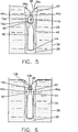
- Figure 5 shows the contact of Figure 4 electrically terminated to one of the conductors shown in Figure 3.
- Figure 6 shows the contact of Figure 4 electrically terminated to the other conductor of Figure 3.
- Connector block 10 used in accordance with the present invention is shown.
- Connector block 10 is used to terminate electrical wires 12 which are shown in Figure 3.
- Connector block 10 generally includes an elongate plastic housing 16 having a planar upper surface 18 and a plurality of circular apertures 20 extending therethrough.
- An upstanding wall 19 about each aperture 20 supports an electrical terminal module 22.
- Each terminal module 22 terminates in insulation displacing fashion, pairs of identical wires 12, two types of which are shown in Figure 3.
- Each pair of wires 12 can include a first pair of wires 12a having a center conductor 13a surrounded by insulation 15a of relatively large diameter or a second pair of wires 12b having a center conductor 13b and insulation 15b of smaller diameter therearound.
- the connector block 10, as well as the terminal module 22 and the method of terminating wires 12 are more fully shown and described in commonly assigned U.S. Patent No. 4,993,966; issued February 19, 1991, which is incorporated by reference herein for all purposes.
- each terminal module 22 includes a base 24 supported within circular aperture 20, a cap 26 movable supported over base 24, and insulation displacing contacts 28 supported between the base 24 and cap 26.
- Cap 26 includes openings 30 which position wires 12 over insulation displacing contacts 28. Movement of the cap 26 toward base 24 under actuation of screw 32, causes wires 12 to be terminated in insulation displacing fashion onto contacts 28.
- Terminal module 22 includes a sealing gel 34 ( Figures 4 through 6) which provides for an environmental seal at the connection between wires 12 and insulation displacing contacts 28.
- Gel 34 is of the type commonly used for such purpose. In the present embodiment silicone is used as a sealing gel. Removal of wires 12 may be effected by reverse actuation of screw 32 which draws cap 26 upwardly away from base 24 and dislodges wires 12 from insulation displacing contacts 28. Terminal module 22 may then be reused to terminate another pair of wires 12. In fact, terminal module 22 may be used to initially terminate a pair of larger wires 12a and then subsequently used to terminate a pair of smaller wires 12b.
- wire 12a In telephone applications, which is the environment in which the present invention especially is used, two sizes of wire are typically employed.
- Larger wire 12a (Fig. 3) is 18 1/2 AWG solid wire, commonly referred to as F-drop.
- Wire 12a has a conductor diameter of .035 inches, and a D-shaped insulation having a diameter of approximately .160 inches.
- the present invention also terminates smaller wire 12b which is 24 AWG solid wire having a conductor diameter of .020 inches and insulation diameter of .040 inches.
- the connector of the present invention is designed to permit repeated terminations of pairs of both wires 12a and 12b in an environmentally sealed manner.
- the present invention contemplates providing a mechanism to the return gel 34 displaced by the initial termination and removal of one of wires 12, so that a subsequent termination may also be environmentally sealed.
- FIG. 4 shows schematically insulation displacing contact 28 supported in a container 36 representing area between base 24 and cap 26 (Fig. 1).
- Container 36 is filled with a sealing gel 34 as described in detail in the above-identified 966 patent.
- Insulation displacing contact 28 includes an upper insulation displacing portion 38 and a pair of spaced-apart beams 40 defining therebetween a conductor receiving slot 42.
- upper insulation displacing portion 38 includes spaced knife-like edges 38a which sever the insulation of wires which are inserted therein.
- Conductive engagement is made within slot 42 by inwardly facing surfaces 40a of beams 40.
- Figure 5 shows wire 12a terminated by contact 28. Once wire 12a is terminated by contact 28, a certain amount of gel 14 will be displaced thereby. When wire 12a is removed, and another wire, such as wire 12b, is subsequently terminated, the displaced gel may not adequately seal the location of the engagement of the wire 12b with contact 28.
- Plunger 44 is responsive to the termination and removal of wires 12 to replace the gel 14 displaced by termination.
- Plunger 44 is an elongate generally rectangular member formed of a resiliently compressible elastomer, such as urethane.
- Plunger 44 includes a pair of spaced planar members 46 connected by an elongate central web 48. As shown in Figure 4, plunger 44 is positioned on contact 28 with web 48 disposed within slot 42. (see also Fig. 1) Each of planar members 46 straddles contact 28.
- the compressible construction of plunger 44 makes it compressibly responsive to the termination of wire 12a.
- Wire 12a is terminated by moving the wire downwardly into engagement with insulation displacing portion 18 so that the insulation 15a thereof is pierced by knife-like edges 38a. Further downward movement of wire 12a causes conductive engagement of conductor 13a with inwardly facing surfaces 40a of beams 40 within slot 42. This movement of wire 12a also compresses plunger 44 so that an upper surface 49 thereof is urged from its original position shown in Figure 4 to a compressed position shown in Figure 5.
- a certain amount of gel 14 is displaced or wiped away from beams 40 as well as from slot 42 by the termination of wire 12a.
- plunger 44 When wire 12a is removed from termination with contact 28, plunger 44 will resiliently return to its original position shown in Figure 4.
- the upper surface 49 of plunger 44 serves to return displaced gel pooled thereon, to a position adjacent insulation displacing portion 38.
- wire 12b which is terminated in a manner similar to that of wire 12a described above, will also be terminated in sealed engagement with insulation displacing contact 28.
- the gel 34 has been replaced along beams 40 of contact 28 as well as within the upper portion of slot 42.
- the gel 34 will effectively seal the interface between the conductor 13b of wire 12b and the inwardly facing surfaces 40a of beams 40.
- Plunger 44 will again be resiliently compressed by the termination of wire 12b to permit further subsequent replacement of displaced gel 34.
- the present invention contemplates numerous subsequent terminations of wires 12a and 12b to contact 28 while still maintaining sealed engagement with contact 28.
Landscapes
- Connector Housings Or Holding Contact Members (AREA)
- Coupling Device And Connection With Printed Circuit (AREA)
Applications Claiming Priority (2)
| Application Number | Priority Date | Filing Date | Title |
|---|---|---|---|
| US07/698,629 US5090917A (en) | 1991-05-10 | 1991-05-10 | Insulation displacing connector for providing repeatable sealed termination of electrical conductors |
| US698629 | 1991-05-10 |
Publications (3)
| Publication Number | Publication Date |
|---|---|
| EP0512836A2 true EP0512836A2 (de) | 1992-11-11 |
| EP0512836A3 EP0512836A3 (en) | 1993-06-30 |
| EP0512836B1 EP0512836B1 (de) | 1996-04-17 |
Family
ID=24806037
Family Applications (1)
| Application Number | Title | Priority Date | Filing Date |
|---|---|---|---|
| EP92304127A Expired - Lifetime EP0512836B1 (de) | 1991-05-10 | 1992-05-07 | Schneidklemmverbinder zum wiederholbaren abgedichteten Verbinden von elektrischen Leitern |
Country Status (4)
| Country | Link |
|---|---|
| US (1) | US5090917A (de) |
| EP (1) | EP0512836B1 (de) |
| CA (1) | CA2067646C (de) |
| DE (1) | DE69209884T2 (de) |
Cited By (2)
| Publication number | Priority date | Publication date | Assignee | Title |
|---|---|---|---|---|
| EP0948832A4 (de) * | 1996-10-16 | 1999-12-29 | Reltec Corp | Anschlussleiste |
| DE102009036281A1 (de) * | 2009-08-06 | 2011-02-10 | Phoenix Contact Gmbh & Co. Kg | Elektrische Verbindung zwischen einem Verbindungselement und einem Kabel |
Families Citing this family (14)
| Publication number | Priority date | Publication date | Assignee | Title |
|---|---|---|---|---|
| US5557250A (en) * | 1991-10-11 | 1996-09-17 | Raychem Corporation | Telecommunications terminal block |
| US6302723B1 (en) | 1991-10-11 | 2001-10-16 | Tyco Electronics Corporation | Telecommunications terminal block |
| US5454732A (en) * | 1992-10-01 | 1995-10-03 | The Whitaker Corporation | Sealed electrical connector providing insulation displacement wire termination |
| US5250651A (en) * | 1992-10-30 | 1993-10-05 | Minnesota Mining And Manufacturing Company | Crosslinked polyether polyol sealant |
| US5248265A (en) * | 1992-11-30 | 1993-09-28 | The Whitaker Corporation | Sealable electrical interconnection assembly |
| US5423694A (en) * | 1993-04-12 | 1995-06-13 | Raychem Corporation | Telecommunications terminal block |
| USD352699S (en) | 1993-05-07 | 1994-11-22 | The Whitaker Corporation | Electrical connector module for telephone cable conductors |
| USD355407S (en) | 1993-05-07 | 1995-02-14 | The Whitaker Corporation | Electrical connector module for telephone cable conductors |
| US5742223A (en) | 1995-12-07 | 1998-04-21 | Raychem Corporation | Laminar non-linear device with magnetically aligned particles |
| DE102006007989A1 (de) * | 2006-02-21 | 2007-08-30 | Robert Bosch Gmbh | Elektrischer Stecker mit abgedichteten Metalleinlegeteilen |
| DE102008013317B4 (de) * | 2008-03-10 | 2010-10-14 | Adc Gmbh | Verfahren zur Herstellung einer Aderanschlussleiste mit Gelfüllung |
| US7985094B2 (en) * | 2008-09-15 | 2011-07-26 | Adc Gmbh | Connector block |
| US8480428B1 (en) * | 2012-01-09 | 2013-07-09 | Devin Sper | Waterproof BNC connector |
| JOP20200040A1 (ar) * | 2017-08-18 | 2020-02-18 | Whelen Eng | بنية ختم الفتحة |
Family Cites Families (7)
| Publication number | Priority date | Publication date | Assignee | Title |
|---|---|---|---|---|
| US4645285A (en) * | 1985-08-26 | 1987-02-24 | Amp Incorporated | Sealed insulation displacement connector |
| US4741709A (en) * | 1985-11-22 | 1988-05-03 | Raychem Corporation | Gel filled enclosure |
| US4734061A (en) * | 1986-12-31 | 1988-03-29 | Bell Communications Research, Inc. | Telecommunications terminal block |
| FR2620870B1 (fr) * | 1987-09-18 | 1990-01-05 | Lacoste Albert | Dispositif de liaison separable entre une broche conductrice et au moins un fil de connexion |
| US4998894A (en) * | 1988-10-06 | 1991-03-12 | Raychem Corporation | Coaxial cable connector seal |
| US4954098A (en) * | 1989-11-01 | 1990-09-04 | Minnesota Mining And Manufacturing Company | Sealed insulation displacement connector |
| US4993966A (en) * | 1990-04-27 | 1991-02-19 | Thomas & Betts Corporation | Electrical connector block |
-
1991
- 1991-05-10 US US07/698,629 patent/US5090917A/en not_active Expired - Lifetime
-
1992
- 1992-04-30 CA CA002067646A patent/CA2067646C/en not_active Expired - Fee Related
- 1992-05-07 DE DE69209884T patent/DE69209884T2/de not_active Expired - Fee Related
- 1992-05-07 EP EP92304127A patent/EP0512836B1/de not_active Expired - Lifetime
Cited By (2)
| Publication number | Priority date | Publication date | Assignee | Title |
|---|---|---|---|---|
| EP0948832A4 (de) * | 1996-10-16 | 1999-12-29 | Reltec Corp | Anschlussleiste |
| DE102009036281A1 (de) * | 2009-08-06 | 2011-02-10 | Phoenix Contact Gmbh & Co. Kg | Elektrische Verbindung zwischen einem Verbindungselement und einem Kabel |
Also Published As
| Publication number | Publication date |
|---|---|
| EP0512836B1 (de) | 1996-04-17 |
| CA2067646A1 (en) | 1992-11-11 |
| CA2067646C (en) | 1995-09-19 |
| DE69209884T2 (de) | 1996-09-05 |
| DE69209884D1 (de) | 1996-05-23 |
| EP0512836A3 (en) | 1993-06-30 |
| US5090917A (en) | 1992-02-25 |
Similar Documents
| Publication | Publication Date | Title |
|---|---|---|
| US5090917A (en) | Insulation displacing connector for providing repeatable sealed termination of electrical conductors | |
| US3808582A (en) | Pre-loaded electrical connecting device | |
| EP0312550B1 (de) | Isolierungsverstellanordnung | |
| WO1992015130A1 (en) | Terminal block | |
| EP0631344B1 (de) | Abgedichteter Schneidklemmverbinder | |
| US4512619A (en) | Insulation displacement terminal for an electrical connector _and environmental sealing means therefor | |
| US5525078A (en) | Electrical plug connector | |
| CA1215152A (en) | Cable clamp for an electrical connector | |
| US3959868A (en) | Tool and adapter for electrical connector unit using insulation piercing contacts | |
| US5492484A (en) | Multiple connector insulation displacement contact | |
| WO1983001154A1 (en) | Wire connector | |
| US4412374A (en) | Device for clamping an insulated cable wire to a terminal element | |
| US3821691A (en) | Wire terminal | |
| US6113421A (en) | Strain relief mechanism for an insulation displacement connector | |
| US5281170A (en) | Round-to-flat shielded connector assembly | |
| KR890015460A (ko) | 압착코넥터 및 그 설치방법 | |
| US4611874A (en) | Device for making LSA-PLUS contact with conductor wires of different types and sizes | |
| US6123566A (en) | Terminal strip with integrated strain relief mechanism for an insulation displacement connector | |
| USRE32810E (en) | Electrical contact for terminating insulated conductors | |
| US4701137A (en) | Electrical connector for coaxial cables | |
| US5246381A (en) | Electrical terminal for modulator connector | |
| US5911593A (en) | Electrical conductor terminal and a method of connecting an electrical conductor to a terminal | |
| US5238428A (en) | Round-to-flat shielded connector assembly | |
| CA1116710A (en) | Insulated electrical conductor locking arrangement and method | |
| EP0263127B1 (de) | Vorrichtung und verfahren zum formen einer kabelhülle, bestehend aus einer deckschicht, einer gewirkten hülle und leitern |
Legal Events
| Date | Code | Title | Description |
|---|---|---|---|
| PUAI | Public reference made under article 153(3) epc to a published international application that has entered the european phase |
Free format text: ORIGINAL CODE: 0009012 |
|
| AK | Designated contracting states |
Kind code of ref document: A2 Designated state(s): DE FR GB IT |
|
| PUAL | Search report despatched |
Free format text: ORIGINAL CODE: 0009013 |
|
| AK | Designated contracting states |
Kind code of ref document: A3 Designated state(s): DE FR GB IT |
|
| 17P | Request for examination filed |
Effective date: 19931223 |
|
| RAP3 | Party data changed (applicant data changed or rights of an application transferred) |
Owner name: THOMAS & BETTS CORPORATION |
|
| 17Q | First examination report despatched |
Effective date: 19950822 |
|
| GRAH | Despatch of communication of intention to grant a patent |
Free format text: ORIGINAL CODE: EPIDOS IGRA |
|
| GRAA | (expected) grant |
Free format text: ORIGINAL CODE: 0009210 |
|
| AK | Designated contracting states |
Kind code of ref document: B1 Designated state(s): DE FR GB IT |
|
| REF | Corresponds to: |
Ref document number: 69209884 Country of ref document: DE Date of ref document: 19960523 |
|
| ET | Fr: translation filed | ||
| ITF | It: translation for a ep patent filed | ||
| PLBE | No opposition filed within time limit |
Free format text: ORIGINAL CODE: 0009261 |
|
| STAA | Information on the status of an ep patent application or granted ep patent |
Free format text: STATUS: NO OPPOSITION FILED WITHIN TIME LIMIT |
|
| 26N | No opposition filed | ||
| PGFP | Annual fee paid to national office [announced via postgrant information from national office to epo] |
Ref country code: FR Payment date: 20000419 Year of fee payment: 9 |
|
| PGFP | Annual fee paid to national office [announced via postgrant information from national office to epo] |
Ref country code: GB Payment date: 20000420 Year of fee payment: 9 Ref country code: DE Payment date: 20000420 Year of fee payment: 9 |
|
| REG | Reference to a national code |
Ref country code: FR Ref legal event code: TP Ref country code: FR Ref legal event code: CA |
|
| PG25 | Lapsed in a contracting state [announced via postgrant information from national office to epo] |
Ref country code: GB Free format text: LAPSE BECAUSE OF NON-PAYMENT OF DUE FEES Effective date: 20010507 |
|
| GBPC | Gb: european patent ceased through non-payment of renewal fee |
Effective date: 20010507 |
|
| PG25 | Lapsed in a contracting state [announced via postgrant information from national office to epo] |
Ref country code: FR Free format text: LAPSE BECAUSE OF NON-PAYMENT OF DUE FEES Effective date: 20020131 |
|
| PG25 | Lapsed in a contracting state [announced via postgrant information from national office to epo] |
Ref country code: DE Free format text: LAPSE BECAUSE OF NON-PAYMENT OF DUE FEES Effective date: 20020301 |
|
| PGFP | Annual fee paid to national office [announced via postgrant information from national office to epo] |
Ref country code: IT Payment date: 20060531 Year of fee payment: 15 |
|
| PG25 | Lapsed in a contracting state [announced via postgrant information from national office to epo] |
Ref country code: IT Free format text: LAPSE BECAUSE OF NON-PAYMENT OF DUE FEES Effective date: 20070507 |