EP0512923B1 - Auf einem abzuzweigenden Kabel anzubringende Abzweigdose, insbesondere für ein unterirdisches Netz - Google Patents
Auf einem abzuzweigenden Kabel anzubringende Abzweigdose, insbesondere für ein unterirdisches Netz Download PDFInfo
- Publication number
- EP0512923B1 EP0512923B1 EP19920401273 EP92401273A EP0512923B1 EP 0512923 B1 EP0512923 B1 EP 0512923B1 EP 19920401273 EP19920401273 EP 19920401273 EP 92401273 A EP92401273 A EP 92401273A EP 0512923 B1 EP0512923 B1 EP 0512923B1
- Authority
- EP
- European Patent Office
- Prior art keywords
- box according
- tapping box
- connection members
- boxes
- clamping
- Prior art date
- Legal status (The legal status is an assumption and is not a legal conclusion. Google has not performed a legal analysis and makes no representation as to the accuracy of the status listed.)
- Expired - Lifetime
Links
- 238000010079 rubber tapping Methods 0.000 title claims 33
- 239000004020 conductor Substances 0.000 claims description 50
- 230000000712 assembly Effects 0.000 claims description 23
- 238000000429 assembly Methods 0.000 claims description 23
- 230000007935 neutral effect Effects 0.000 claims description 17
- 239000011810 insulating material Substances 0.000 claims description 11
- 230000000295 complement effect Effects 0.000 claims description 9
- 239000013013 elastic material Substances 0.000 claims description 2
- 238000007789 sealing Methods 0.000 claims description 2
- 239000004429 Calibre Substances 0.000 claims 2
- 230000008901 benefit Effects 0.000 description 5
- 238000009826 distribution Methods 0.000 description 3
- 210000005069 ears Anatomy 0.000 description 3
- 230000004323 axial length Effects 0.000 description 2
- 229920001971 elastomer Polymers 0.000 description 2
- 239000000806 elastomer Substances 0.000 description 2
- 230000008030 elimination Effects 0.000 description 2
- 238000003379 elimination reaction Methods 0.000 description 2
- 238000003780 insertion Methods 0.000 description 2
- 230000037431 insertion Effects 0.000 description 2
- 239000000463 material Substances 0.000 description 2
- 210000002105 tongue Anatomy 0.000 description 2
- 241001415961 Gaviidae Species 0.000 description 1
- 238000004026 adhesive bonding Methods 0.000 description 1
- 238000004040 coloring Methods 0.000 description 1
- 239000000470 constituent Substances 0.000 description 1
- 238000010276 construction Methods 0.000 description 1
- 238000002788 crimping Methods 0.000 description 1
- 238000005520 cutting process Methods 0.000 description 1
- 238000005553 drilling Methods 0.000 description 1
- 230000000694 effects Effects 0.000 description 1
- 239000004519 grease Substances 0.000 description 1
- 238000011065 in-situ storage Methods 0.000 description 1
- 238000002955 isolation Methods 0.000 description 1
- 239000002184 metal Substances 0.000 description 1
- 238000000034 method Methods 0.000 description 1
- 210000000056 organ Anatomy 0.000 description 1
- 230000035515 penetration Effects 0.000 description 1
- 230000002787 reinforcement Effects 0.000 description 1
- 230000000717 retained effect Effects 0.000 description 1
- 230000003313 weakening effect Effects 0.000 description 1
Images



Classifications
-
- H—ELECTRICITY
- H01—ELECTRIC ELEMENTS
- H01R—ELECTRICALLY-CONDUCTIVE CONNECTIONS; STRUCTURAL ASSOCIATIONS OF A PLURALITY OF MUTUALLY-INSULATED ELECTRICAL CONNECTING ELEMENTS; COUPLING DEVICES; CURRENT COLLECTORS
- H01R9/00—Structural associations of a plurality of mutually-insulated electrical connecting elements, e.g. terminal strips or terminal blocks; Terminals or binding posts mounted upon a base or in a case; Bases therefor
- H01R9/03—Connectors arranged to contact a plurality of the conductors of a multiconductor cable, e.g. tapping connections
- H01R9/031—Connectors arranged to contact a plurality of the conductors of a multiconductor cable, e.g. tapping connections for multiphase cables, e.g. with contact members penetrating insulation of a plurality of conductors
Definitions
- the present invention relates generally to the junction boxes implemented for the connection of at least one branched cable to a passing main cable having, in practice, several insulated conductors, namely, three phase conductors and one conductor. neutral, duly twisted.
- They generally comprise two jaws, which are intended to jointly surround the main cable, primary connection members, which, one for each of the conductors of the main cable, are intended to come into contact with the conductive core of these conductors, secondary connection members, which are intended to be put in electrical connection with the conductive core of the conductors of the branch cable to be connected, conductive connection means establishing an electrical connection between the primary connection members and the connection members secondary corresponding to them, and two half-boxes of insulating material, which, adapted to be closed one on the other by closing means available to the operator, are intended to jointly contain the assembly.
- the primary connection members being distributed in a star around a common axis, like the conductors of the main cable passing to be fitted, access to these primary connection members may prove to be difficult in a trench, in particular with regard to those which are then oriented towards the bottom thereof.
- connection of the conductors of the branch cable must in practice be done directly within this trench, and the reclosure one on the other of the two half-boxes is ensured by simple bolts, unfortunately all accessible on the same side of the box.
- the present invention generally relates to a junction box advantageously free from the drawbacks succinctly set out above and further comprising other advantages.
- This junction box which is therefore intended for the connection of at least one branched cable to a main cable passing through several insulated conductors, in particular for an underground network, is of the type comprising two jaws, which are intended to jointly surround the main cable , primary connection members, which, one for each of the conductors of the main cable, are intended to come into contact with the conductive core of these conductors by being buttressed by said jaws, secondary connection members, which are intended to be placed in electrical connection with the conductive core of the conductors of the branch cable, conductive connection means establishing an electrical connection between the primary connection members and the secondary connection members which correspond to them, and two half-boxes in insulating material, which, adapted to be closed one over the other by means of closure by dis position of the operator, are intended to jointly contain the assembly, and, according to a first aspect, it is generally characterized in that the primary connection members are fixed relative to the jaws, said jaws are mounted movable one with respect to the other under the control of at least one clamping assembly,
- the two clamping elements of a clamping assembly are each individually guided axially in a well of the corresponding half-box.
- centering means are preferably provided between them.
- the number of tightenings to be carried out in the trench is thus advantageously limited.
- the two tightening elements of each of the tightening assemblies are preferably both individually accessible from the outside, on the faces of the corresponding half-boxes generally opposite one with respect to to the other.
- the two half-boxes can advantageously be identical to each other, for the benefit of their cost.
- the junction box according to the invention is further characterized in that the secondary connection members which it comprises are plug-in connection members capable of cooperating in engagement with complementary plug-in connection members belonging to a plug to be added as a corollary to the branch cable.
- connection of the conductors of the branch cable to this plug can advantageously be done outside the trench.
- junction box according to the invention is further characterized in that its closure means comprise at least one toggle closure assembly with manual operation.
- closure means are exclusively formed of a plurality of such toggle closure assemblies.
- toggle closure assemblies advantageously do not require, for this implementation, any specific tool.
- the junction box according to the invention is further characterized in that, according to a fourth aspect, it is associated with it several sets of different separators each corresponding respectively to different diameters for the main cable, these separators differing from each other only by their thickness from one of these games to the other as well as by their coloring.
- the same junction box can advantageously be suitable for a whole range of main cables of different diameters, for the benefit of increased standardization of the two half-boxes to be used, and therefore for the benefit of an increased reduction in the costs of these.
- the main cable 10 comprises three phase conductors 12P and a neutral conductor 12N, all insulated.
- the 12P phase conductors have a sectoral cross section, in a quarter of a circle.
- the neutral conductor 12N has a circular cross section.
- the assembly is twisted, and is part of a circular cross section, being jointly surrounded, first by a shielding screen 13, formed by a metal ribbon wound in contiguous turns, then by an outer envelope 14, produced in insulating material.
- Such a main cable 10 is usually used for the transport of low voltage electrical energy in three-phase current, and it is most often buried, then belonging to a network commonly known as an underground network.
- a branch cable 11 itself comprising three phase conductors 15P and a neutral conductor 15N, it is therefore necessary to dig a trench.
- junction box 16 It is also necessary to use a junction box 16.
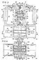
- the junction box 16 comprises, overall, in a manner known per se, and according to methods described in more detail later, two jaws 18A, 18B, which are intended to jointly surround the main cable 10, connection members primary 19P, 19N, which, one for each of the conductors 12P, 12N of the main cable 10, are intended to come into contact with the conductive core thereof, being duly buttressed by the jaws 18A, 18B , secondary connection members 22P, 22N, which are intended to be placed in electrical connection with the conductive core of the conductors 15P, 15N of the branch cable 11, conductive connection means establishing an electrical connection between the primary connection members 19P , 19N and the secondary connection members 22P, 22N which correspond to them, and two half-boxes 25A, 25B, in material insulating, which, adapted to be closed one on the other by closing means available to the operator, are intended to jointly contain the assembly.
- the primary connection members 19P, 19N are fixed relative to the jaws 18A, 18B, these jaws 18A, 18B are movable relative to each other under the control of at least one clamping assembly 28,
- this clamping assembly 28 is formed of two complementary clamping elements 29A, 29B, one per jaw 18A, 18B, these clamping elements 29A, 29B are only capable of engaging one with the other than when the two half-boxes 25A, 25B are closed one on the other, and at least one of these clamping elements 29A, 29B is accessible to the operator from the outside of two half-boxes 25A, 25B.
- the two half-boxes 25A, 25B are identical to each other.
- a first compartment 30, in which extend, transversely, in the middle zone, between ribs suitable for guiding them, the jaws 18A, 18B, with, to the right of these jaws 18A, 18B , for the local embedding of these, a protuberance 31, and, on the other hand, opposite this protuberance 31, a compartment 32, which is of smaller volume than that of the preceding compartment 30, and in which extend, longitudinally, the secondary connection members 22P, 22N.
- the two half-boxes 25A, 25B face each other along a joint plane M.
- the two half-boxes 25A, 25B also have, projecting, perpendicular to the joint plane M, lugs 37, which, by penetration into notches 37 ′ arranged in correspondence , are likely to guide one relative to each other when they are brought together.
- the two half-boxes 25A, 25B form, finally, jointly, by semi-circular cradles 38, on the two opposite transverse faces of the compartment 30, openings of circular section 39 which locally interrupt the joint plane M.
- connection members 22P, 22N For access to the secondary connection members 22P, 22N, they form, jointly, by semi-circular cradles 40, on the two opposite transverse faces of the compartment 32, openings of circular section 42 which locally interrupt the plane of attached M.
- the seals 36 which are relatively flat, are made of soft and waterproof elastomer.
- annular seals 44 which locally surround the main cable 10, and which are also made of soft and waterproof elastomer.
- the two half-boxes 25A, 25B are of conventional construction, within the reach of those skilled in the art.
- the two jaws 18A, 18B have the general shape of an omega stirrup and they are mounted movable relative to one another under the control of two identical clamping assemblies 28 established at a distance from each other.
- the primary connection members 19P, 19N intervene by perforation.
- They therefore comprise, for drilling the insulating sheath of the conductors 12P, 12N of the main cable 10, teeth 51.
- these teeth 51 are elongated perpendicular to the main faces of the jaws 18A, 18B, and therefore parallel to the direction of elongation of the main cable 10.
- the primary connection members 19P corresponding to the phase conductors 12P each individually, form separate blocks, suitably isolated from the jaws 18A, 18B.
- the two primary connection members 19P associated with the jaw 18A are jointly encased in a bowl 52A, made of insulating material, by which they are attached thereto.
- the primary connection member 19P associated with the jaw 18B is encased in a bowl 52B, made of insulating material, by which it is attached to this jaw 18B.
- each of the jaws 18A, 18B and the corresponding half-box 25A, 25B are provided disengageable temporary fastening means.
- these disengageable temporary fastening means intervene between the associated cup 52A, 52B and the corresponding half-box 25A, 25B.
- they comprise at least one lug 53, which, integral with the bowl 52A, 52B, coming in one piece with the latter, is forcibly engaged on the corresponding lug 46 of the half-box 25A, 25B concerned.
- only one ear 53 is thus provided on each of the cups 52A, 52B.
- these cups 52A, 52B are suitably secured to the jaws 18A, 18B, for example by bonding or force engagement.
- connection members 19P which they carry are suitably joined to them, for example by gluing or force engagement.
- the conductive connection means intended to establish an electrical connection between the primary connection members 19P, 19N and the secondary connection members 22P, 22N are constituted by sections of cable 55P, 55N insulated.
- the primary connection members 19P, 19N therefore each have a bore 56 suitable for crimping the conductive core of the corresponding section of cable 55P, 55N.
- separators 59, 60 are also provided to be arranged crosswise between the conductors 12P, 12N of the main cable 10 to separate them from each other in line with the jaws 18A, 18B.
- one of these separators namely the separator 59, comprises engagement means by which it is able to be engaged with at least one of the jaws 18A, 18B, for guiding those -this, in addition to the guidance already provided by ribs of the corresponding half-box 25A, 25B.
- this separator 59 includes engagement means for one and the other of the jaws 18A, 18B.
- the separator 59 also has, in its central zone, a recess 62 specific to the engagement of the separator 60.
- this separator 60 has, transversely, a T-shaped configuration, with, on the one hand, a leg 63, by which it is adapted to fit into the separator 59, by engagement in the recess 62 thereof , and which, to facilitate its insertion between the conductors 12P, 12N of the main cable 10, ends with a point 64, and, on the other hand, at the end of the leg 63 opposite this point 64, a heel 65.
- Ribs 66 present transversely projecting from the leg 63 are intended to cooperate in abutment with the separator 59 to limit the engagement of the latter in the recess 62 of the latter.
- the separator 60 also has, transversely, on one of the faces of this leg 63, a groove 67 suitable for receiving the neutral conductor 12N of the main cable 10.
- the separator 60 thus having to be arranged in a determined orientation relative to the main cable 10, there is provided, between it and the jaw 18B of which an integral part is the primary connection member 19N corresponding to this neutral conductor 12N, means for foolproof.
- the corresponding part of its heel 65 is shaped accordingly, for interlocking cooperation with a notch 68 of this jaw 18B.
- a lug 69 capable of cooperating in engagement with a bore 69 'provided for this purpose on the jaw 18B, FIG. 2.
- the tip 64 of the leg 63 of the separator 60 can also be extended by a tongue 70 suitable for further facilitating insertion between the conductors 12P, 12N of the main cable. 10.
- the separators 59, 60 are made of insulating material, and, in practice, of hard insulating material.
- the separator 60 is honeycombed.
- the thicknesses of the separators 59, 60 thus formed are adapted to the diameter of the main cable 10, and several sets of different separators 59, 60 are provided, each corresponding respectively to different diameters for this main cable 10, these separators 59, 60 differing from each other, from one game to another, only by their thickness, and, also, to better distinguish them, by their color.
- the two clamping elements 29A, 29B of each of the clamping assemblies 28 are each individually guided axially, with gentle friction, in a well 71 of the corresponding half-box 25A, 25B, and there is between them centering means specific to to facilitate the coming into engagement with each other.
- they comprise, as clamping members, one, the clamping element 29B, a threaded barrel 29′B forming a screw, the other, the clamping element 29A, a threaded socket 29 ′ A forming a nut, and, for constituting the centering means acting between them, the threaded barrel 29′B has at its end a generally frustoconical extension 72 and the threaded sleeve 29′A has, at its outlet, a chamfer 73.
- the two clamping members 29′A, 29′B which constitute for a clamping assembly 28 such a threaded socket 29′A and such a threaded barrel 29′B each pass respectively through the corresponding ears 49 of the jaws 18A, 18B, and they have, below these, after interposition of a distribution washer 74, for action on these ears 49, at the bottom of the well 71 corresponding to the half-boxes 25A, 25B, a head support 75.
- clamping elements 29A, 29B which is accessible from the outside further comprises, in engagement with this support head 75, in the extension thereof, and rotatably mounted with gentle friction in the well 71 corresponding to the half-box 25A, 25B, a clamping head 76 suitable for driving the assembly in rotation.
- the two clamping elements 29A, 29B of each of the clamping assemblies 28 are both individually accessible from the outside.
- the clamping head 76 of a clamping element 29A, 29B is formed by a plastic end piece molded onto the support head 75 which it extends, while this support head 75, and the organ, threaded barrel 29′B or threaded sleeve 29′A, of which it is integral, is metallic.
- At least one seal is provided between such a clamping head 76 and the corresponding well 71.
- the clamping head 76 of each of the clamping elements 29A, 29B has, transversely, at least one weakened breaking zone 79.
- FIG. 13 there are provided, axially staggered on the clamping head 76 of each of the clamping elements 29A, 29B, two weakening zones 79 ′, 79 ⁇ each corresponding respectively to different breaking ratings, that, 79 ′, The rupture of which corresponds to the smallest size being disposed above that, 79 ⁇ , the rupture of which corresponds to the largest size.
- the embrittlement zones with calibrated rupture, 79, or 79 ′ and 79 ⁇ are each formed by an area of reduced section resulting from the presence of an annular groove.
- the clamping head 76 of the clamping elements 29A, 29B has, transversely, for its rotation control, a polygonal section and, in practice, hexagonal.
- a collar 80 is provided in the wells 71 of the two half-boxes 25A, 25B, projecting from the internal surface of these wells 71.
- the wells 71 of the half-boxes 25A, 25B extend beyond their bottom 45, and, for the reinforcement of the latter, the two wells 71 which are thus projecting therein are connected to the one to the other by two ribs 81.
- a rotary control applied to the clamping head 76 of any of the clamping elements 29A, 29B of a clamping assembly 28 does not inadvertently and parasitically induce a rotation drive of the other of these, there is associated with each of the two half-boxes 25A, 25B, a bar 83A, 83B which, by two caps 84, is adapted to be engaged simultaneously on the two clamping heads 76 present on the bottom 45 of such a half-box 25A, 25B.
- the secondary connection members 22P, 22N are plug-in connection members capable of cooperating in engagement with the complementary plug-in connection members 85P, 85N belonging to a plug 86 to be added as a corollary to the branch cable 11 concerned .
- the secondary connection members 22P, 22N operate on the bottom of a cell 87 projecting from one of the transverse faces of the compartment 32 of the junction box 16, around the opening 42 corresponding thereof, and these are sockets whose outlets are all in the same transverse plane.
- the plug-in connection members 85P, 85N are pins.
- the pin forming the neutral connection member 85N of this plug 86 has a length greater than that of the pins forming its phase connection members 85P.
- connection, or disconnection, of the neutral takes place before that of the phases.
- the secondary phase connection members 22P of the junction box 16 are distributed circularly, at 120 ° from one another, around the secondary neutral connection member 22N, equidistant therefrom.
- Two of the secondary phase connection members 22P are jointly embedded in a core 88A, in the form of a gutter, which extends from one to the other of the cradles 40 of the half-box 25A, and which, for its wedging relative to the latter, has, projecting, in its central region, a rib 89 by which it is engaged between two ribs 90 of this half-box 25A.
- the third phase secondary connection member 22P and the secondary neutral connection member 22N are jointly embedded in a core 88B, which, complementary to the previous one, extends from one to the other of the cradles 40 of the half-box 25B, and which, for its setting thereon, has, projecting, in its median zone, a rib 89 by which it is engaged between two ribs 90 of this half-box 25B .
- the two cores 88A, 88B which are made of insulating material, and for example of hard insulating material, jointly form a block of circular cross section.
- the junction box 16 comprises, back to back, in this block, two identical sets of plug-in secondary connection members 22P, 22N, each suitable for the implementation of a file 86.
- the sockets constituting the secondary connection members 22P, 22N are each individually paired with identical sockets which, oriented in opposite directions, are located in their extension.
- the conductive core of the cable sections 55P, 55N is crimped onto these secondary connection members 22P, 22N in the central, massive zone, remaining between such sockets, in line with the ribs 89 of the cores 88A, 88B.
- these cores 88A, 88B are molded onto the corresponding end of the cable sections 55P, 55N.
- plug-in connection members 85P, 85N of a plug 86 also intervene by perforation.
- each of these plug-in connection members 85P, 85N is individually associated with sealing means.
- each of them is to do this belted, leaving the plug 86, by a ring 96, of elastic material, which is in one piece with a seal 97 common to the 'assembly, and which is intended to be applied on the core 88A, 88B concerned, around the outlet of the socket forming the secondary connection member 22P, 22N corresponding.
- each of the cells 87 of the junction box 16 according to the invention has latching means specific to a disengageable locking of the associated plug 86.
- a shutter 100 is provided to be placed in the other cell 87 in place of a plug 86.
- this shutter 100 Like sheet 86, this shutter 100 includes a seal 97 with rings 96, but these are established around false pins 102.
- this shutter 100 is such that the elastically deformable tongues 98 of a cell 87 can be hooked on it.
- the closing means of the junction box 16 comprises at least one toggle closure assembly 105, for manual and rapid implementation.
- closure means comprise at least one such toggle closure assembly 105 along each of two opposite edges of the two half-boxes 25A, 25B.
- three toggle closure assemblies 105 are thus provided, two on the side of the compartment 30, on either side of its protuberance 31, and one on the side of the compartment 32, in line with the middle part. of it.
- five toggle closure assemblies 105 may be provided, three on one side, and two on the other.
- the closing means of the junction box 16 consist in practice exclusively of the only toggle closure assemblies 105 thus implemented.
- such a toggle closure assembly 105 generally comprises, on the one hand, two flanges 106A, 106B, which are each mounted to rotate on the two respectively. corresponding half-boxes 25A, 25B, by simply being hooked on ribs 107A, 107B provided for this purpose thereon, and, on the other hand, at the disposal of the operator, a lever 108, on which are both articulated, at a distance from each other, these flanges 106A, 106B.
- latching means Between the lever 108 and one of the half-boxes 25A, 25B, in this case the half-box 25A, intervene, for the closed position of this lever 108, latching means.
- the lever 108 has, at its end, a spout 109, by which it can forcely engage in a groove 110 provided in correspondence on the half-box 25A, in the angle zone of the latter. .
- junction box 16 for the connection, using a junction box 16 according to the invention, of a branch cable 11 on a cable main 10 passing belonging to an underground network, it is proceeded as follows.
- the main cable 10 is locally updated, and it is locally stripped of its insulating outer casing 14 and of its shielding screen 13.
- the separators 59, 60 corresponding to its diameter are then arranged, in a cross, between its conductors 12P, 12N, with engagement of the neutral conductor 12N with the groove 67 of the separator 60.
- annular seals 44 are each opened locally by a slot, not visible in the figures, which preferably extends obliquely relative to their axis.
- the two half-boxes 25A, 25B constituting this junction box 16 are then brought closer to each other, with engagement of their jaws 18A, 18B between the arms 61 of the separator 59.
- the clamping members 29′A, 29′B of the clamping elements 29A , 29B then engage one with the other, or, in other words, come into engagement with each other, and these clamping members 29′A, 29′B are thus put in position to be able to come subsequently in clamping engagement with each other by screwing action on the clamping heads 76 associated therewith.
- the jaws 18A, 18B advantageously remain in place in the half-boxes 25A, 25B, being retained there by the ear 53 of the bowl 52A, 52B which is associated with them, which prevents them from inadvertently escaping from these half-boxes 25A, 25B.
- the flanges 106A, 106B of the toggle closure assemblies 105 are then hooked onto the half-boxes 25A, 25B, then, by tilting their lever 108, at the closure of these toggle closure assemblies 105, and thereby that of the half-boxes 25A, 25B.
- the closure of the junction box 16 according to the invention takes place advantageously even before these primary connection members 19P, 19N are energized.
- the clamping head 76 of the clamping elements 29A, 29B of the clamping assemblies 28 comprises two embrittlement zones with calibrated rupture 79 ′, 79 ⁇ , it is carried out in two stages, a first until the 79 ′ calibrated rupture embrittlement zone, a second until the 79 ⁇ calibrated rupture embrittlement zone breaks, acting alternately on one and the other of the clamping heads 76 concerned.
- connection of the primary connection members 19P, 19N with the conductive core of the conductors 12P, 12N of the main cable 10 can only be obtained when the two half-boxes 25A, 25B are duly closed one on the other.
- a plug 86 is connected to the branch cable 11 outside the trench.
- toggle fastening assemblies can be replaced by conventional assemblies of the screw-nut type, which can be used for tightening one on the other of the two half-boxes, either on the screw side or on the nut side.
Landscapes
- Connector Housings Or Holding Contact Members (AREA)
- Laying Of Electric Cables Or Lines Outside (AREA)
Claims (32)
- Abzweigdose zur Abzweigung mindestens eines Kabels, das an einem Hauptkabel abgezweigt ist, welches an mehreren isolierten Leitern vorbeiläuft, insbesondere für ein unterirdisches Netz, der Art mit zwei Klemmen (18A, 18B), die dazu bestimmt sind, das Hauptkabel (10) zusammen zu umgeben, ersten Verbindungsorganen (19P, 19N), von denen jeweils eines für jeden der Leiter (12P, 12N) des Hauptkabels (10) vorgesehen ist und die dazu bestimmt sind, in Kontakt mit der leitenden Seele von diesen Leitern (12P, 12N) zu kommen, wobei sie vorschriftsmäßig durch die Klemmen (18A, 18B) gestützt werden, zweiten Verbindungsorganen (22P, 22N), die dazu bestimmt sind, in elektrische Verbindung mit der leitenden Seele der Leiter (15P, 15N) des abgezweigten Kabels (11) gebracht zu werden, Leiterverbindungsmitteln (55P, 55N), die eine elektrische Verbindung zwischen den ersten Verbindungsorganen (19P, 19N) und den ihnen entsprechenden zweiten Verbindungsorganen (22P, 22N) herstellen, und zwei Gehäusehälften (25A, 25B) aus einem isolierenden Material, die geeignet sind, durch Verschlußmittel, welche einer Bedienungsperson zur Verfügung stehen, miteinander verbunden zu werden und dazu bestimmt sind, die Anordnung zusammen aufzunehmen,
dadurch gekennzeichnet,
daß die ersten Verbindungsorgane (19P, 19N) in Bezug auf die Klemmen (18A, 18B) befestigt sind, daß die Klemmen (18A, 18B) bewegbar unter der Kontrolle mindestens einer Klemmanordnung (28) gegeneinander bewegbar sind, daß die Klemmanordnung (28) aus zwei komplementären Klemmelementen (29A, 29B) gebildet ist, wobei jeweils eines pro Klemme (18A, 18B) vorgesehen ist, daß die Klemmelemente (29A, 29B) nicht in Eingriff miteinander zu kommen, wenn die beiden Dosenhälften (25A, 25B) nicht aneinander befestigt sind, und daß mindestens eines der Klemmelemente (29A, 29B) für eine Bedienungsperson von der Außenseite der beiden Gehäusehälften (25A, 25B) derart zugänglich ist, daß einerseits dann, wenn die beiden Gehäusehälften (25A, 25B) nicht aneinander befestigt sind, eine Betätigung des einen und / oder des anderen der Klemmelemente (29A, 29B), die von der Außenseite der beiden Gehäusehälften (25A, 25B) erfolgt, genügt, um ein Klemmen der Klemmen (18A, 18B) und auf dieser Basis die Verbindung der ersten Verbindungsorgane (19P, 19N) mit der leitenden Seele der Leiter (12P, 12N) des Hauptkabels (10) zu gewährleisten, und daß andererseits diese Verbindung nicht erreicht werden kann, wenn die beiden Gehäusehälften (25A, 25B) nicht vorschriftsmäßig miteinander verbunden sind. - Abzweigdose nach dem Anspruch 1,
dadurch gekennzeichnet,
daß die beiden Klemmelemente (29A, 29B) einer Klemmanordnung (28) jeweils individuell in einem Schacht (71) der entsprechenden Gehäusehälfte (25A, 25B) in Axialrichtung geführt ist und zwischen ihnen Zentriermittel wirken, die geeignet sind, das in Kontaktkommen des einen mit dem anderen zu erleichtern. - Abzweigdose nach dem Anspruch 2,
dadurch gekennzeichnet,
daß von den beiden Klemmelementen (29A, 29B) einer Klemmanordnung (28) eines einen mit einem Gewinde versehenen Schaft (29′B) aufweist und eine Schraube bildet und daß andere eine mit einem Innengewinde versehene Hülse (29′A) aufweist und eine Mutter bildet und daß zur Bildung der Zentriermittel, die zwischen ihnen wirken, der mit einem Gewinde versehene Schaft (29′B) an seiner Außenseite eine allgemein kegelstumpfartige Verlängerung (72) aufweist. - Abzweigdose nach dem Anspruch 3,
dadurch gekennzeichnet,
daß von den beiden Klemmelementen (29A, 29B) einer Klemmanordnung (28) eines einen mit einem Gewinde versehenen Schaft (29′B) aufweist und eine Schraube bildet und das andere eine mit einem Innengewinde versehene Hülse (29′A) aufweist, die eine Mutter bildet, und zur Bildung der Zentriermittel, die zwischen ihnen wirken, die mit einem Innengewinde versehene Hülse (29′A) an ihrer Öffnung eine Seitenfase aufweist. - Abzweigdose nach irgendeinem der Ansprüche 1 bis 4,
dadurch gekennzeichnet,
daß zumindest dasjenige der Klemmelemente (29A, 29B) einer Klemmanordnung (28), das von der Außenseite her zugänglich ist, einen Klemmkopf (76) besitzt, der in Querrichtung zumindest eine Sollbruchstelle (79, 79′, 79˝) aufweist, die bei einer vorgegebenen Belastung bricht. - Abzweigdose nach dem Anspruch 5,
dadurch gekennzeichnet,
daß der Klemmkopf (76) in Axialrichtung versetzt zwei Sollbruchstellen (79′, 79˝) aufweist, die bei einer vorgegebenen Belastung brechen und jeweils unterschiedlichen Bruchfestigkeiten entsprechen, wobei diejenige (79′), die der schwacheren Festigkeit entspricht, oberhalb von derjenigen (79˝), deren Bruch der größeren Festigkeit entspricht, angeordnet ist. - Abzweigdose nach irgendeinem der Ansprüche 5, 6,
dadurch gekennzeichnet,
daß die beiden Klemmelemente (29A, 29B) einer Klemmanordnung (28) beide individuell von außen an den entsprechenden Flächen der Gehäusehälften (25A, 25B), die sich allgemein einander gegenüberliegen, zugänglich sind. - Abzweigdose nach irgendeinem der Ansprüche 1 bis 7,
dadurch gekennzeichnet,
daß die Klemmen (18A, 18B) beweglich gegeneinander unter der Kontrolle der beiden Klemmanordnungen (28), die mit Abstand zueinander angeordnet sind, montiert sind. - Abzweigdose nach irgendeinem der Ansprüche 1 bis 8,
dadurch gekennzeichnet,
daß die zweiten Verbindungsorgane (22P, 22N) steckbare Verbindungsorgane sind, die geeignet sind, in Eingriff mit komplementären steckbaren Verbindungsorganen (85P) zusammenzuwirken, die zu einem Stecker (86) gehören, der zusätzlich auf das abgezweigte Kabel (11) aufgesteckt werden kann. - Abzweigdose nach dem Anspruch 9,
dadurch gekennzeichnet,
daß die zweiten Verbindungsorgane (22P, 22N) drei Verbindungsorgane von Phase (22P) und ein neutrales Verbindungsorgan (22N) aufweisen und daß die Verbindungsorgane von Phase (22P) kreisförmig um 120° gegeneinander versetzt um das neutrale Verbindungsorgan (22) mit gleichem Abstand zu diesem angeordnet sind. - Abzweigdose nach irgendeinem der Ansprüche 9, 10,
dadurch gekennzeichnet,
daß die zweiten Verbindungsorgane (22P, 22N) Hülsen sind, deren Öffnungen alle in derselben Querebene liegen. - Abzweigdose nach dem Anspruch 11,
dadurch gekennzeichnet,
daß dem neutralen Verbindungsorgan (22N) an dem zugeordneten Stecker (86) ein Zapfen (85N) entspricht, dessen Länge größer ist als die von den Zapfen (85P) dieses Steckers (86), die den Verbindungsorganen von Phase (22P) entsprechen. - Abzweigdose nach irgendeinem der Ansprüche 9 bis 12,
dadurch gekennzeichnet,
daß jedem der steckbaren Verbindungsorgane (85P, 85N), die der zugeordnete Stecker (86) aufweist, individuell ein Dichtungsmittel (96) zugeordnet ist. - Abzweigdose nach irgendeinem der Ansprüche 9 bis 13,
dadurch gekennzeichnet,
daß die zweiten Verbindungsorgane (22P, 22N) an der Rückseite einer Steckerbuchse (87), die für einen Eingriff mit dem zugeordneten Stecker (86) geeignet ist, in Eingriff kommen. - Abzweigdose nach dem Anspruch 14,
dadurch gekennzeichnet,
daß die Steckbuchse (87) Rastmittel (98) aufweist, die für eine lösbare Rastverbindung mit dem zugeordneten Stecker (86) geeignet sind. - Abzweigdose nach irgendeinem der Ansprüche 9 bis 15,
dadurch gekennzeichnet,
daß sie Rückwand an Rückwand zwei identische Sätze von steckbaren zweiten Verbindungsorganen (22P, 22N) aufweist, die jeweils geeignet sind, durch einen Stecker (86) betätigt zu werden. - Abzweigdose nach irgendeinem der Ansprüche 1 bis 16,
dadurch gekennzeichnet,
daß die Verriegelungsmittel mindestens eine Verriegelungsanordnung mit einem Kniehebel (105) besitzt, die manuell betätigt werden kann. - Abzweigdose nach dem Anspruch 17,
dadurch gekennzeichnet,
daß die Kniehebel-Verriegelungsanordnung (105) zwei Flansche (106A, 106B) aufweist, die jeweils drehbar an den beiden Gehäusehälften (25A, 25B) montiert sind und zur Betätigung durch eine Bedienungsperson, einen Hebel (108) aufweisen, an dem die Flansche (106A, 106B) mit Abstand zueinander angelenkt sind. - Abzweigdose nach dem Anspruch 18,
dadurch gekennzeichnet,
daß jeder der Flansche (106A, 106B) der Kniehebel-Verriegelungsanordnung (105) einfach an der Gehäusehälfte (25A, 25B), die sie trägt, eingehakt ist. - Abzweigdose nach irgendeinem der Ansprüche 17 bis 19,
dadurch gekennzeichnet,
daß zwischen dem Hebel (108) der Kniehebel-Verriegelungsanordnung (105) und einer der Gehäusehälften (25A, 25B) Rastmittel (109, 110) für die Verriegelungsstellung des Hebels (108) wirken. - Abzweigdose nach irgendeinem der Ansprüche 17 bis 20,
dadurch gekennzeichnet,
daß die Verriegelungsmittel mindestens eine Kniehebel-Verriegelungsanordnung (105) entlang jeder der beiden gegenüberliegenden Seiten der beiden Gehäusehälften (25A, 25B) aufweisen. - Abzweigdose nach irgendeinem der Ansprüche 1 bis 21,
dadurch gekennzeichnet,
daß zwischen den beiden Gehäusehälften (25A, 25B) mindestens eine Dichtung (36) aus einem elastischen Material vorgesehen ist, die, wenn die beiden Gehäusehälften (25A, 25B) miteinander verbunden sind, durch die Verrieglungsmittel komprimiert wird. - Abzweigdose nach irgendeinem der Ansprüche 1 bis 22,
dadurch gekennzeichnet,
daß die beiden Gehäusehälften (25A, 25B) identisch zueinander sind. - Abzweigdose nach irgendeinem der Ansprüche 1 bis 23,
dadurch gekennzeichnet,
daß zwischen jeder Klemme (18A, 18B) und der entsprechenden Gehäusehälfte (25A, 25B) Mittel (46, 53) zur temporären lösbaren Verbindung vorgesehen sind. - Abzweigdose nach dem Anspruch 24,
dadurch gekennzeichnet,
daß mindestens eines der ersten Verbindungsorgane (19P, 19N) in einen Deckel (52A, 52B) aus einem isolierenden Material eingelassen ist, durch den es an der entsprechenden Klemme (18A, 18B) gehalten ist, und daß die temporären Verbindungsmittel (56, 53) zwischen dem Deckel (52A, 52B) und der entsprechenden Gehäusehälfte (25A, 25B) wirken. - Abzweigdose nach dem Anspruch 25,
dadurch gekennzeichnet,
daß die temporären Verbindungsmittel (46, 53) mindestens eine Öse (53) aufweisen, die einstückig mit dem Deckel (52A, 52B) ausgebildet ist und unter Zwang mit einem Vorsprung (46), welcher einstückig mit der betroffenen Gehäusehälfte (25A, 25B) ausgebildet ist, in Eingriff gebracht wird. - Abzweigdose nach irgendeinem der Ansprüche 1 bis 26,
dadurch gekennzeichnet,
daß zwei Trennelemente (59, 60), die über Kreuz zwischen den beiden Leitern (12P, 12N) des Hauptkabels (10) anzuordnen sind, vorgesehen sind, wobei eines der Trennelemente (59) Eingriffsmittel (61) aufweist, durch die es geeignet ist, in Verbindung mit einer der Klemmen (18A, 18B) für die Führung von dieser in Eingriff gebracht zu werden. - Abzweigdose nach Anspruch 27,
dadurch gekennzeichnet,
daß das Trennelement (59) Eingriffsmittel (61) für die eine und die andere der Klemmen (18A, 18B) aufweist. - Abzweigdose nach dem Anspruch 28,
dadurch gekennzeichnet,
daß das Trennelement (59) allgemein im Aufriß die Form des Buchstabens H besitzt. - Abzweigdose nach irgendeinem der Ansprüche 1 bis 26,
dadurch gekennzeichnet,
daß zwei Trennelemente (59, 60) vorgesehen sind, die über Kreuz zwischen den beiden Leitern (12P, 12N) des Hauptkabels (10) angeordnet werden können, und daß zumindest zwischen einem der Trennelemente (60) und einer der Klemmen (18B) Unverwechselbarkeitsmittel (65 bis 68, 69 bis 69′) vorgesehen sind. - Abzweigdose nach irgendeinem der Ansprüche 1 bis 26,
dadurch gekennzeichnet,
daß zwei Trennelemente (59, 60) vorgesehen sind, die über Kreuz zwischen den Leitern (12P, 12N) des Hauptkabels (10) angeordnet werden können, und daß mehrere unterschiedliche Sätze von Trennelementen (59, 60) vorgesehen sind, von denen jeder jeweils unterschiedlichen Durchmessern für das Hauptkabel (10) entspricht. - Abzweigdose nach dem Anspruch 31,
dadurch gekennzeichnet,
daß von einem Satz zum anderen sich die Trennelemente (59, 60) nicht durch ihre Dicke unterscheiden.
Applications Claiming Priority (2)
| Application Number | Priority Date | Filing Date | Title |
|---|---|---|---|
| FR9105690 | 1991-05-10 | ||
| FR9105690A FR2676313B1 (fr) | 1991-05-10 | 1991-05-10 | Boite de derivation a rapporter sur un cable passant, notamment pour reseau souterrain. |
Publications (2)
| Publication Number | Publication Date |
|---|---|
| EP0512923A1 EP0512923A1 (de) | 1992-11-11 |
| EP0512923B1 true EP0512923B1 (de) | 1995-02-15 |
Family
ID=9412673
Family Applications (1)
| Application Number | Title | Priority Date | Filing Date |
|---|---|---|---|
| EP19920401273 Expired - Lifetime EP0512923B1 (de) | 1991-05-10 | 1992-05-07 | Auf einem abzuzweigenden Kabel anzubringende Abzweigdose, insbesondere für ein unterirdisches Netz |
Country Status (4)
| Country | Link |
|---|---|
| EP (1) | EP0512923B1 (de) |
| DE (1) | DE69201398D1 (de) |
| ES (1) | ES2069393T3 (de) |
| FR (1) | FR2676313B1 (de) |
Families Citing this family (3)
| Publication number | Priority date | Publication date | Assignee | Title |
|---|---|---|---|---|
| DE4403811C1 (de) * | 1994-02-08 | 1995-06-14 | Felten & Guilleaume Energie | Kabelabzweigmuffe für Hausanschlüsse |
| NL1001192C2 (nl) * | 1995-09-14 | 1997-03-20 | Lovink Terborg Bv | Kabelmof. |
| PL197279B1 (pl) * | 1998-11-18 | 2008-03-31 | Reichle & De Massari Ag | Urządzenie rozdzielcze |
Family Cites Families (4)
| Publication number | Priority date | Publication date | Assignee | Title |
|---|---|---|---|---|
| FR2615661B1 (fr) * | 1987-05-20 | 1989-07-21 | Materiel Electr Soc Ind | Dispositif de connexion pour le branchement de derivations sur des cables principaux enterres |
| FR2630865B1 (fr) * | 1988-04-27 | 1991-12-13 | Niled Sa | Borne de derivation pour le raccordement d'un conducteur d'une ligne aerienne isolee a un conducteur de derivation isole |
| FR2645683B1 (fr) * | 1989-04-10 | 1996-06-14 | Mars Actel | Boite de raccordement pour branchement de cables de derivation sur un cable principal |
| FR2649257B1 (fr) * | 1989-06-30 | 1991-09-13 | Lens Cableries | Boite de derivation etanche pour cable d'energie a basse tension |
-
1991
- 1991-05-10 FR FR9105690A patent/FR2676313B1/fr not_active Expired - Fee Related
-
1992
- 1992-05-07 ES ES92401273T patent/ES2069393T3/es not_active Expired - Lifetime
- 1992-05-07 EP EP19920401273 patent/EP0512923B1/de not_active Expired - Lifetime
- 1992-05-07 DE DE69201398T patent/DE69201398D1/de not_active Expired - Lifetime
Also Published As
| Publication number | Publication date |
|---|---|
| DE69201398D1 (de) | 1995-03-23 |
| FR2676313A1 (fr) | 1992-11-13 |
| ES2069393T3 (es) | 1995-05-01 |
| EP0512923A1 (de) | 1992-11-11 |
| FR2676313B1 (fr) | 1993-08-20 |
Similar Documents
| Publication | Publication Date | Title |
|---|---|---|
| EP0170545B1 (de) | Isolierter Abzweigverbinder für elektrische Kabel | |
| FR2462035A1 (fr) | Connecteur electrique separable | |
| EP0334704A1 (de) | Bajonettschnellkupplung | |
| FR2527390A1 (fr) | Dispositif de liaison electrique par enfichage | |
| LU83885A1 (fr) | Connecteur electrique pour conducteur isole | |
| EP0112258B1 (de) | Elektrische Sicherheitssteckdose insbesondere für explosive Atmosphäre | |
| EP3758154B1 (de) | Stromanschlussmodul mit verriegelungs-/entriegelungssystem der stromkabelenden in dem modul, klemmleiste, die eine vielzahl von unabhängigen anschlussmodulen umfasst | |
| EP3758161A1 (de) | Stromanschlusseinheit, die ein anschlussmodul und stromkabelenden umfasst, die in diesem modul je nach gewünschter einschubposition verriegelt/entriegelt werden können, und klemmleiste, die eine vielzahl von unabhängigen anschlussmodulen umfasst | |
| EP0312438B1 (de) | Selbstabisolierender Verbinder für einen elektrischen Leiter | |
| EP3758165B1 (de) | Anschlussmodul, anschlusseinheit mit klemmleiste mit einer vielzahl von solchen anschlussmodulen und luftfahrzeugstruktur mit solcher anschlusseinheit | |
| EP0211741B1 (de) | Anschlussdose mit seitlicher Verbindung | |
| CH659741A5 (fr) | Dispositif de jonction d'un cable electrique aerien et d'un cable souterrain a basse tension. | |
| EP0512923B1 (de) | Auf einem abzuzweigenden Kabel anzubringende Abzweigdose, insbesondere für ein unterirdisches Netz | |
| CH398730A (fr) | Dispositif de connexion | |
| FR2703193A1 (fr) | Appareil électrique, en particulier bloc de jonction, à borne de connexion mettant en Óoeuvre un écrou à serrage rapide. | |
| EP1383211B1 (de) | Crimpenverfahren für einen Kontakt zu Kabelsträngen | |
| FR2661564A1 (fr) | Connecteur electrique verrouillable. | |
| EP3457499A1 (de) | Elektrische verbindungsvorrichtung | |
| FR2947672A1 (fr) | Ensemble de connexions | |
| EP1020677B1 (de) | Verbinderanordnung | |
| EP0664578A1 (de) | Verbinder für Koaxialkabel | |
| FR2659801A1 (fr) | Fiche de prise de courant. | |
| EP1410468A1 (de) | Ausziehgerät für einen elektrischen stecker relativ zu einer elektrischen steckdose | |
| FR2794902A1 (fr) | Connecteur de derivation compact d'au moins un cable de derivation de neutre sur un cable principal de neutre et mise a la terre simultanee | |
| FR2517107A1 (fr) | Borne a cadre ouverte pour appareils de commutation electriques |
Legal Events
| Date | Code | Title | Description |
|---|---|---|---|
| PUAI | Public reference made under article 153(3) epc to a published international application that has entered the european phase |
Free format text: ORIGINAL CODE: 0009012 |
|
| AK | Designated contracting states |
Kind code of ref document: A1 Designated state(s): BE DE ES GB IT NL |
|
| 17P | Request for examination filed |
Effective date: 19921208 |
|
| 17Q | First examination report despatched |
Effective date: 19940621 |
|
| GRAA | (expected) grant |
Free format text: ORIGINAL CODE: 0009210 |
|
| AK | Designated contracting states |
Kind code of ref document: B1 Designated state(s): BE DE ES GB IT NL |
|
| PG25 | Lapsed in a contracting state [announced via postgrant information from national office to epo] |
Ref country code: NL Effective date: 19950215 |
|
| GBT | Gb: translation of ep patent filed (gb section 77(6)(a)/1977) |
Effective date: 19950222 |
|
| REF | Corresponds to: |
Ref document number: 69201398 Country of ref document: DE Date of ref document: 19950323 |
|
| REG | Reference to a national code |
Ref country code: ES Ref legal event code: FG2A Ref document number: 2069393 Country of ref document: ES Kind code of ref document: T3 |
|
| ITF | It: translation for a ep patent filed | ||
| PG25 | Lapsed in a contracting state [announced via postgrant information from national office to epo] |
Ref country code: DE Effective date: 19950516 |
|
| NLV1 | Nl: lapsed or annulled due to failure to fulfill the requirements of art. 29p and 29m of the patents act | ||
| PLBE | No opposition filed within time limit |
Free format text: ORIGINAL CODE: 0009261 |
|
| STAA | Information on the status of an ep patent application or granted ep patent |
Free format text: STATUS: NO OPPOSITION FILED WITHIN TIME LIMIT |
|
| 26N | No opposition filed | ||
| PGFP | Annual fee paid to national office [announced via postgrant information from national office to epo] |
Ref country code: ES Payment date: 19970505 Year of fee payment: 6 |
|
| PGFP | Annual fee paid to national office [announced via postgrant information from national office to epo] |
Ref country code: GB Payment date: 19970506 Year of fee payment: 6 |
|
| PGFP | Annual fee paid to national office [announced via postgrant information from national office to epo] |
Ref country code: BE Payment date: 19970520 Year of fee payment: 6 |
|
| PG25 | Lapsed in a contracting state [announced via postgrant information from national office to epo] |
Ref country code: GB Free format text: LAPSE BECAUSE OF NON-PAYMENT OF DUE FEES Effective date: 19980507 |
|
| PG25 | Lapsed in a contracting state [announced via postgrant information from national office to epo] |
Ref country code: ES Free format text: LAPSE BECAUSE OF EXPIRATION OF PROTECTION Effective date: 19980508 |
|
| PG25 | Lapsed in a contracting state [announced via postgrant information from national office to epo] |
Ref country code: BE Free format text: LAPSE BECAUSE OF NON-PAYMENT OF DUE FEES Effective date: 19980531 |
|
| BERE | Be: lapsed |
Owner name: SOC. INDUSTRIELLE DE CONSTRUCTION D'APPAREILS ET D Effective date: 19980531 |
|
| GBPC | Gb: european patent ceased through non-payment of renewal fee |
Effective date: 19980507 |
|
| REG | Reference to a national code |
Ref country code: ES Ref legal event code: FD2A Effective date: 20000201 |
|
| PG25 | Lapsed in a contracting state [announced via postgrant information from national office to epo] |
Ref country code: IT Free format text: LAPSE BECAUSE OF NON-PAYMENT OF DUE FEES;WARNING: LAPSES OF ITALIAN PATENTS WITH EFFECTIVE DATE BEFORE 2007 MAY HAVE OCCURRED AT ANY TIME BEFORE 2007. THE CORRECT EFFECTIVE DATE MAY BE DIFFERENT FROM THE ONE RECORDED. Effective date: 20050507 |