EP0512989B1 - Strömungskontrollvorrichtung - Google Patents
Strömungskontrollvorrichtung Download PDFInfo
- Publication number
- EP0512989B1 EP0512989B1 EP19900911195 EP90911195A EP0512989B1 EP 0512989 B1 EP0512989 B1 EP 0512989B1 EP 19900911195 EP19900911195 EP 19900911195 EP 90911195 A EP90911195 A EP 90911195A EP 0512989 B1 EP0512989 B1 EP 0512989B1
- Authority
- EP
- European Patent Office
- Prior art keywords
- fluid
- cylindrical body
- flow
- poppet
- seat
- Prior art date
- Legal status (The legal status is an assumption and is not a legal conclusion. Google has not performed a legal analysis and makes no representation as to the accuracy of the status listed.)
- Expired - Lifetime
Links
- 239000012530 fluid Substances 0.000 claims abstract description 79
- 230000002093 peripheral effect Effects 0.000 claims abstract description 12
- OKTJSMMVPCPJKN-UHFFFAOYSA-N Carbon Chemical class [C] OKTJSMMVPCPJKN-UHFFFAOYSA-N 0.000 claims description 3
- 238000007789 sealing Methods 0.000 claims description 3
- 230000006866 deterioration Effects 0.000 claims description 2
- 238000001125 extrusion Methods 0.000 claims 1
- 230000000694 effects Effects 0.000 abstract 1
- 230000009977 dual effect Effects 0.000 description 6
- 230000003628 erosive effect Effects 0.000 description 4
- 239000000446 fuel Substances 0.000 description 3
- 230000008901 benefit Effects 0.000 description 2
- 230000004044 response Effects 0.000 description 2
- 238000013459 approach Methods 0.000 description 1
- 229910052799 carbon Inorganic materials 0.000 description 1
- 239000000919 ceramic Substances 0.000 description 1
- 239000000463 material Substances 0.000 description 1
- 230000007246 mechanism Effects 0.000 description 1
- 230000003068 static effect Effects 0.000 description 1
- 230000007704 transition Effects 0.000 description 1
- 239000013585 weight reducing agent Substances 0.000 description 1
Images
Classifications
-
- F—MECHANICAL ENGINEERING; LIGHTING; HEATING; WEAPONS; BLASTING
- F16—ENGINEERING ELEMENTS AND UNITS; GENERAL MEASURES FOR PRODUCING AND MAINTAINING EFFECTIVE FUNCTIONING OF MACHINES OR INSTALLATIONS; THERMAL INSULATION IN GENERAL
- F16K—VALVES; TAPS; COCKS; ACTUATING-FLOATS; DEVICES FOR VENTING OR AERATING
- F16K1/00—Lift valves or globe valves, i.e. cut-off apparatus with closure members having at least a component of their opening and closing motion perpendicular to the closing faces
- F16K1/32—Details
- F16K1/34—Cutting-off parts, e.g. valve members, seats
- F16K1/44—Details of seats or valve members of double-seat valves
-
- Y—GENERAL TAGGING OF NEW TECHNOLOGICAL DEVELOPMENTS; GENERAL TAGGING OF CROSS-SECTIONAL TECHNOLOGIES SPANNING OVER SEVERAL SECTIONS OF THE IPC; TECHNICAL SUBJECTS COVERED BY FORMER USPC CROSS-REFERENCE ART COLLECTIONS [XRACs] AND DIGESTS
- Y10—TECHNICAL SUBJECTS COVERED BY FORMER USPC
- Y10T—TECHNICAL SUBJECTS COVERED BY FORMER US CLASSIFICATION
- Y10T137/00—Fluid handling
- Y10T137/8593—Systems
- Y10T137/86493—Multi-way valve unit
- Y10T137/86718—Dividing into parallel flow paths with recombining
- Y10T137/86759—Reciprocating
- Y10T137/86767—Spool
- Y10T137/86775—With internal passage
Definitions
- This invention relates to the timing of a balanced dual poppet valve for a fluid control device.
- a sleeve member of a secondary poppet is carried by a cylindrical body and urged into engagement with a seat on the housing of the valve by a resilient member prior to the engagement of a primary poppet to assure that flow communication through the cylindrical body terminates prior to the flow communication through the primary flow path from an entrance port to an output port in a fluid system.
- a balance dual poppet valve wherein a cylindrical member is connected to an actuation member.
- the cylindrical body has a first end with a first poppet having a segment of a parabolic curve extending from a peripheral surface and a second end with a second poppet having a segment of a parabolic curve extending from a peripheral surface.
- the body of the valve has a cavity or bore with a entrance port connected to a source of fluid and an outlet port connected to a fluid system.
- the cylindrical body is located in cavity or bore and moved by an actuation member to control the communication of fluid between the entrance port and outlet port.
- the space relationship between the first poppet and a first seat and the second poppet and a second seat establishes the rate at which the fluid flows to the outlet port.
- the interior of the bore adjacent the second end of the cylindrical body had a parabolic shape such that the path of the fluid flow from the second poppet is reversed and directed through the center of the cylindrical body.
- the quantity of fluid which flows past the second seat is combined with the quantity of fluid which flows past the first seat to meet the fluid demand by the positioning of the cylindrical body by the actuation member.
- the fluid pressure in the fluid that is presented to the bore acts on the first and second poppets in both the static and actuation state to establish substantially equal forces to create a balance .valve and as a result only minimum actuation force is required to move the cylindrical body and establish the required fluid flow from the entrance port to the outlet port.
- the flow control device has a valve with a cylindrical body.
- a sleeve member concentric to the cylindrical body has a bearing section that is located in a groove adjacent the second end of the cylindrical body.
- the sleeve member has a curved surface that extends from the flange and forms an extension for the segment of the parabolic curve that extends from the second end of the cylindrical body.
- a flexible member located in the groove on the cylindrical body acts on the bearing section of the sleeve member to urge the sleeve member toward a stop or the wall of the groove in the cylindrical body.
- the bearing of the sleeve member engages the stop or bottom of the groove such that the curved section on the sleeve forms a continuation of the segment of the parabolic surface on the second end of the cylindrical body.
- the sleeve surrounds the flexible member and protects the flexible member from erosion and damage as the fluid flows between the parabolic surface and second seat.
- the actuation member moves the cylindrical body toward the rest position, where flow is terminated between the entrance port and outlet port, the curved section of the sleeve initially contacts the second seat to interrupt flow through the second poppet.
- the resilient member is compressed between the sleeve and cylindrical body to form a seal to prevent internal leakage from the source into the bore.
- An advantage that this invention provides over the known valves resides in a movable second poppet which allows a balanced condition to be maintained with a first poppet carried by a cylindrical body connected to an actuation member.
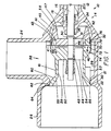
- a fuel flow control device 10 shown in Figure 1 includes an actuation section 12 connected to a valve section 14.
- the actuation section 12 includes shaft seals 20, an actuation shaft or rod 16 and an actuator which is not shown.
- the actuation shaft or rod 16 extends through bearing member 20 located in bore 18 in the housing 22 of the valve section 14.
- fluid under pressure from a source flows through an entrance port 24 to an outlet port 26 connected to a fluid system.
- the valve section has a housing 22 with a cavity or bore 28.
- the housing 22 has a first annular seat 30 and a second annular seat 32.
- the entrance port 24 is located between the first and second annular seats 30 and 32.
- the housing 22 has a curved surface 34 which extends from the second seat 32 to an annular section 36 that surrounds bore 18.
- the curved surface 34 is substantially a parabola and is selected to reverse the flow of fluid that flows past seat 32 toward the outlet port 26 without the creation of turbulence.
- a cylindrical body 38 made up of a first section 40 and a second section 42 is located in bore 28.
- Actuation rod 16 which passes through center hub 44 in the first section 40 has a and center hub 46 in the second section 42 and nut 48 attached thereto.
- a guide pin 41 extending from face 67 aligns the internal flow paths in the first and second sections 40 and 42.
- hub 46 is brought into contact with shoulder 50 on actuation rod 16 such that a unitary structure is created.
- first section 40 has a plurality of guide bearings 57 (only one is shown) which engage surface 21 to maintain the cylindrical body 38 in the axial center of the cavity or bore 28.
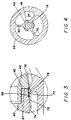
- Center hubs 44 and 46 have a series of radial spokes 50, 52, and 54, see figure 4, that radially extend to the interior of the cylindrical body 38.
- the cylindrical body 38 has a first end 56 and a second end 58.
- Cylindrical body 38 has a smooth bore 39 with an annular flared section 55 adjacent the first end 56.
- the peripheral surface of the cylindrical body 38 includes a first curved surface 60 that extends from a relative constant diameter surface 61 to a shoulder 62.
- the peripheral surface 64 of the shoulder 62 forming a face that engages seat 30 to define a first poppet and seat seal.
- the first section 40 of the cylindrical body 38 also has a groove 66 on the peripheral surface that extends to the face 67 on the end thereof. Face 43 on the end of the second section 42 forms the end wall for groove 66.
- the second section 42 has a peripheral curved surface 45 that extends from end 58 to face 43 and an interior curved surface 47 that extends from end 58 to spokes 50, 52, and 54. Curved surface 45 is essentially in the shape of a parabola while curved surface 47 is concentric to the parabolic surface 34 in housing 22.
- the interior of housing 22 and the second end 58 of the cylindrical body 38 are shaped to reduce turbulence in flow of fluid that passes around the second poppet.
- a flexible member 70 Prior to the joining of the first section 40 with the second section 42, a flexible member 70, see figure 3 is located in groove 66.
- the flexible member 70 must be capable of withstanding varying temperature changes that occur in the supply fluid and still function in an intended manner of sealing and possessing resiliency. While many materials may possess these characteristics for this operation it has been found that laminated graphite functions the best.
- a sleeve member 72 has a body section that is concentric to surface 74 on the peripheral surface of the first section 40 of cylindrical body 38.
- the sleeve member 72 surrounds and protects the flexible member 70 from direct contact with fluid supplied to bore 28 through the entrance port 24.
- a flange 76 on the sleeve member 72 which extends into groove 66 has a curved surface 78 that radially extends from the end face of the flange 76.
- the curved surface 78 forming a face that engages seat 32 to form a second poppet and seat seal.
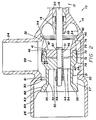
- an input from the actuator moves the actuation push rod 16 which in turn moves the cylindrical body 38 to move face 64 on the first poppet away from seat 30 and allow fluid to flow directly from the entrance port 24 to the outlet port 26 in a manner as shown in figure 2.
- the space relationship between curved surface 60 and seat 30 defines a first volume or quantity of the fluid that directly flows past the first seat 30 to the outlet port 26.
- a second volume or quantity of fluid flows past the second poppet to the interior of the cylindrical body 38.
- the resilient member 70 acts on the flange 76 to bring the same into engagement with a stop or face 43 on the second section 42.
- the curved surface 45 on the second section of the cylindrical body 38 forms a smooth transition for the flow of fluid from bore 28 to the interior of the cylindrical body 38.
- the space relationship between the curved surface 45 and face 32 defines the volume or quantity of fluid that flows past the second seat 32 to the interior of the cylindrical body 38.
- the curved surface 34 on housing 22 and curved surface 47 on the second section 42 of the cylindrical body 38 directs the second quantity of fluid to the interior bore 39 without the creation of substantial turbulence.
- flare 55 allows the second quantity of fluid to be combined with the first quantity of fluid without the creation of turbulence.
- the first and second quantities of fluid are thereafter presented to the outlet port 26 for distribution to the fluid system to meet the demand as indicated by the position of the actuator.
- sleeve member 72 protects the flexible member 70 from erosion and deterioration that could occur should the fluid directly contact the flexible member 70.
- This flow of fluid from the entrance port 24 continues in accordance with the position of the cylindrical body 38 within bore 28.
- the volume of fluid is changed linearly with movement of the cylindrical body 38 because of the relationship of the curved surface 60 with seat 30 and curved surface 45 with seat 32 to meet new or different fluid requirements whenever a new input signal is supplied to the actuator.
- the actuator moves the actuation shaft or rod 16 and cylindrical body 38, which carries the first and second poppets, toward the closing or rest position, as shown in Figure 1. Since the fluid pressure acts on substantially the same area of the first and second poppets, the force to move the cylindrical body 38 is relatively small. As the cylindrical body 38 approaches the rest position, the curved surface 78 on sleeve member 72 of the second poppet engages seat 32 to terminate the flow of fluid past seat 32 into the interior flow path through bore 39 although a small volume of fluid continues to occur past seat 30 to outlet port 26 continues to occur past seat 30.
- the dual poppet valve disclosed herein provides a control for a fluid system with stability and low actuation forces while accurately supplying fluid to the components in the fluid system.
- This dual poppet valve provides a weight reduction over known state of the art valves for fluid systems wherein varying temperatures and large volumes of fluid must be supplied within relative short time periods.
Landscapes
- Engineering & Computer Science (AREA)
- General Engineering & Computer Science (AREA)
- Mechanical Engineering (AREA)
- Lift Valve (AREA)
Claims (8)
- Strömungssteuervorrichtung (10) mit einem Gehäuse (22) und einem Hohlraum (28) darin, welches Gehäuse (22) eine mit einer Fluidquelle verbundene Einlaßöffnung (24) und eine mit einem Fluidsystem verbundene Auslaßöffnung (26) besitzt und welches Gehäuse (22) einen ersten Sitz (30) und einen zweiten Sitz (32) aufweist, die zwischen der Einlaßöffnung (24) und der Auslaßöffnung (26) gelegen sind, sowie ein Ventil (14) mit einem ersten und einem zweiten Tellerventilkörper, die mit einem Betätigungsglied (16) jeweils zum Bewegen des ersten und des zweiten Tellerventilkörpers in bezug auf den ersten (30) und den zweiten Sitz (32), um die Fluidströmung von der Einlaßöffnung zur Auslaßöffnung zu steuern, welches Ventil (14) durch einen zylindrischen Körper (38) gekennzeichnet ist, welcher eine Umfangsfläche (64) mit einem ersten, einem ersten Ende (56) benachbarten, gekrümmten Abschnitt (60) zur Bildung des ersten Tellerventilkörpers besitzt, und welcher zylindrische Körper (38) einen zentralen, mit der Umfangsfläche über eine Reihe radialer Speichen (50, 52, 54) verbundenen Nabenteil (44, 46) besitzt, mit welchem zentralen Nabenteil (44, 46) das Betätigungsglied (16) verbunden ist, wobei am zylindrischen Körper (38) ein Hülsenglied (72) mit einem zur genannten Umfangsfläche (74) konzentrischen Körperabschnitt vorgesehen ist, welches Hülsenglied (72) einen Flanschabschnitt (76) aufweist, der zur Begrenzung einer Nut (66) am zylindrischen Körper (38) an der Umfangsfläche (64), dem zweiten Ende benachbart, anliegt, welches Hülsenglied (72) eine zweite gekrümmte Fläche (78) besitzt, die sich vom Flanschabschnitt (76) radial nach außen erstreckt, welche zweite gekrümmte Fläche (78) das zweite Tellerventilkörperelement bildet, und wobei in der Nut (66) ein biegsames Element (70) angeordnet ist, welches biegsame Element (70) das Hülsenglied (72) gegen einen Anschlag (43) am zylindrischen Körper (38) hin belastet, wobei das Betätigungsglied (16) den zylindrischen Körper (38) derart bewegt, daß dem Fluid gestattet wird, direkt aus dem Hohlraum (28) zwischen den ersten Sitz (30) und den ersten Tellerventilkörper und zwischen den zweiten Sitz (32) und den zweiten Tellerventilkörper, rund um das zweite Ende (58) und durch die Innenbohrung (39) des zylindrischen Körpers (38) zu strömen, um mit der Fluidströmung nach dem ersten Sitz (30) und dem ersten Tellerventilkörper zur Verteilung an die Auslaßöffnung (26) kombiniert zu werden, wobei das Betätigungsglied (16) die Fluidströmung zur Auslaßöffnung (26) unterbricht, indem der zylindrische Körper (38) derart bewegt wird, daß die zweite gekrümmte Fläche (78) anfänglich am zweiten Sitz (32) zur Anlage kommt, um die Strömung durch den zylindrischen Körper (38) zu unterbrechen, und anschließend das biegsame Element (70) zusammenpreßt, bis die erste gekrümmte Fläche (64) am ersten Sitz (30) anliegt, um die direkte Fluidströmung zur Auslaßöffnung (26) zu unterbrechen, wobei das zusammengepreßte biegsame Element (70) die Nut (66) zur Verhinderung von Fluidleckage aus dem Hohlraum (28) in das Fluidsystem abdichtet.
- Strömungssteuervorrichtung (10) mit dem Ventil (14) nach Anspruch 1, bei der die erste und zweite gekrümmte Fläche (64, 78) durch parabolische Konturen gekennzeichnet sind, die den Fluidstrom von der Einlaßöffnung (24) zur Auslaßöffnung (26) leiten, um zur Erfüllung eines bestimmten Programmes eine ruhige und kontrollierte Strömung zu bilden.
- Strömungssteuervorrichtung (10) mit dem Ventil (14) nach Anspruch 2, bei der die parabolischen Konturen mit einer Veränderung der Lage des zylindrischen Körpers (38) eine lineare Veränderung der Fluidströmung gestatten.
- Strömungssteuervorrichtung (10) mit dem Ventil (14) nach Anspruch 3, bei der das biegsame Element (70) ein Ring aus laminiertem Graphit ist, welcher über einen weiten Bereich von auf den Flansch (76) wirkenden Betriebstemperaturen eine ausreichende Elastizität besitzt, um die Hülse während der Betätigung gegen den Anschlag (43) hin zu belasten, und eine ausreichende Zusammendrückbarkeit, um den Hohlraum (28) abzudichten, wenn eine Beendigung der Strömung erwünscht ist.
- Strömungssteuervorrichtung (10) mit dem Ventil (14) nach Anspruch 4, bei der die Anlage der ersten konturierten Fläche (64) an der ersten Fläche (30) nicht erfolgt, bevor nicht das biegsame Element (70) zusammengedrückt ist.
- Strömungssteuervorrichtung (10) mit dem Ventil (14) nach Anspruch 5, bei der der Körperabschnitt des Hülsengliedes (72) das biegsame Element (70) zur Verhinderung einer Zerstörung des biegsamen Elementes (70) vor dem Heraustreten und dem direkten Kontakt mit der Fluidströmung schützt.
- Strömungssteuervorrichtung (10) mit dem Ventil (14) nach Anspruch 6, bei der das Fluid in dem Hohlraum (28) während jeder beliebigen Betriebslage des zylindrischen Körpers (38) und sobald die Fluidströmung aus dem Hohlraum (28) beendet ist auf den ersten und den zweiten Tellerventilkörper mit im wesentlichen gleicher Kraft wirkt.
- Strömungssteuervorrichtung (10) mit dem Ventil (14) nach Anspruch 7, bei der das erste Ende (56) des zylindrischen Körpers (38) eine sich aufweitende Fläche (55) besitzt, wobei sich die Fluidströmung durch die Mitte des zylindrischen Körpers (38) zur Fluidströmung hinter den ersten Sitz (30) ohne Erzeugung wesentlicher Turbulenz hinzufügt.
Applications Claiming Priority (2)
| Application Number | Priority Date | Filing Date | Title |
|---|---|---|---|
| US472581 | 1990-01-30 | ||
| US07/472,581 US4966193A (en) | 1990-01-30 | 1990-01-30 | Timing control for a dual poppet valve |
Publications (2)
| Publication Number | Publication Date |
|---|---|
| EP0512989A1 EP0512989A1 (de) | 1992-11-19 |
| EP0512989B1 true EP0512989B1 (de) | 1993-09-22 |
Family
ID=23876099
Family Applications (1)
| Application Number | Title | Priority Date | Filing Date |
|---|---|---|---|
| EP19900911195 Expired - Lifetime EP0512989B1 (de) | 1990-01-30 | 1990-06-26 | Strömungskontrollvorrichtung |
Country Status (6)
| Country | Link |
|---|---|
| US (1) | US4966193A (de) |
| EP (1) | EP0512989B1 (de) |
| JP (1) | JP2807344B2 (de) |
| AU (1) | AU5963190A (de) |
| DE (1) | DE69003538D1 (de) |
| WO (1) | WO1991011640A1 (de) |
Families Citing this family (12)
| Publication number | Priority date | Publication date | Assignee | Title |
|---|---|---|---|---|
| US5014694A (en) * | 1990-10-15 | 1991-05-14 | Bird Products Corporation | Ambient pressure air/oxygen blender |
| US5118075A (en) * | 1991-02-12 | 1992-06-02 | Allied-Signal Inc. | Seal arrangement for a metering valve |
| US5156181A (en) | 1991-07-22 | 1992-10-20 | Allied-Signal Inc. | Removable seats for a dual poppet valve |
| RU2147092C1 (ru) * | 1999-04-20 | 2000-03-27 | Туленков Анатолий Сергеевич | Двухседельный разгруженный клапан |
| US6135967A (en) | 1999-04-26 | 2000-10-24 | Fiorenza; Anthony Joseph | Respiratory ventilator with automatic flow calibration |
| US6240919B1 (en) | 1999-06-07 | 2001-06-05 | Macdonald John J. | Method for providing respiratory airway support pressure |
| JP2004108518A (ja) * | 2002-09-19 | 2004-04-08 | Aisin Seiki Co Ltd | 流体バルブ装置 |
| US6910851B2 (en) * | 2003-05-30 | 2005-06-28 | Honeywell International, Inc. | Turbofan jet engine having a turbine case cooling valve |
| JP2005069389A (ja) * | 2003-08-26 | 2005-03-17 | Saginomiya Seisakusho Inc | 弁装置 |
| WO2005073604A1 (ja) * | 2004-01-30 | 2005-08-11 | Kabushiki Kaisha Saginomiya Seisakusho | 複座弁 |
| WO2017200497A1 (en) * | 2016-05-20 | 2017-11-23 | Kirpart Otomativ Parcalari Sanayi Ve Ticaret Anonim Sirketi | A thermostat assembly with tandem valves |
| CN112797176B (zh) * | 2021-01-29 | 2021-12-17 | 青岛精锐机械制造有限公司 | 一种可避免密封部受大载荷力的先导式角座阀 |
Family Cites Families (11)
| Publication number | Priority date | Publication date | Assignee | Title |
|---|---|---|---|---|
| DE1252027B (de) * | 1967-10-12 | |||
| GB191105584A (en) * | 1911-03-06 | 1911-06-01 | Johann Stumpf | Improvements relating to Valves. |
| US1896947A (en) * | 1931-11-19 | 1933-02-07 | Glaenzer Harry | Throttle for locomotives |
| US2634754A (en) * | 1948-12-27 | 1953-04-14 | Oil Ct Tool Company | Pilot controlled fluid pressure operated valve |
| US2731036A (en) * | 1951-10-06 | 1956-01-17 | Reynolds Gas Regulator Company | Valve seat structure |
| GB1007437A (en) * | 1961-01-30 | 1965-10-13 | Ass Elect Ind | Improvements relating to valves for controlling the flow of gases and/or vapours |
| US3550623A (en) * | 1967-06-02 | 1970-12-29 | Robertshaw Controls Co | Flow control device |
| US3934613A (en) * | 1973-10-10 | 1976-01-27 | Robertshaw Controls Company | Pneumatically operated pilot relay and system and diverting relay construction utilizing the same or the like |
| US4249572A (en) * | 1980-02-04 | 1981-02-10 | Deere & Co | Self-relieving fluid coupling |
| US4344449A (en) * | 1980-05-16 | 1982-08-17 | The United States Of America As Represented By The United States Department Of Energy | Fast-acting valve and uses thereof |
| DE3534135A1 (de) * | 1985-09-25 | 1987-04-02 | Hp & Hp Chemie Stellglieder | Abdichtungseinrichtung an einer kolben-zylinderanordnung, insbesondere zur abdichtung des ventilkegels an ventilen mit druckausgleich |
-
1990
- 1990-01-30 US US07/472,581 patent/US4966193A/en not_active Expired - Fee Related
- 1990-06-26 WO PCT/US1990/003607 patent/WO1991011640A1/en not_active Ceased
- 1990-06-26 AU AU59631/90A patent/AU5963190A/en not_active Abandoned
- 1990-06-26 DE DE90911195T patent/DE69003538D1/de not_active Expired - Lifetime
- 1990-06-26 EP EP19900911195 patent/EP0512989B1/de not_active Expired - Lifetime
- 1990-06-26 JP JP51013490A patent/JP2807344B2/ja not_active Expired - Lifetime
Also Published As
| Publication number | Publication date |
|---|---|
| WO1991011640A1 (en) | 1991-08-08 |
| JP2807344B2 (ja) | 1998-10-08 |
| AU5963190A (en) | 1991-08-21 |
| JPH05503754A (ja) | 1993-06-17 |
| US4966193A (en) | 1990-10-30 |
| DE69003538D1 (de) | 1993-10-28 |
| EP0512989A1 (de) | 1992-11-19 |
Similar Documents
| Publication | Publication Date | Title |
|---|---|---|
| US4966193A (en) | Timing control for a dual poppet valve | |
| US7635113B2 (en) | Ball valve seat arrangement | |
| US3960364A (en) | High pressure tight shutoff valve seal | |
| EP2188555B1 (de) | Metallische dichtungsscheibe mit einer elastomerischen verstärkung für flüssigkeitsregelrn | |
| CN101361032B (zh) | 装有整流罩的压力调节器 | |
| US4174728A (en) | Sliding-gate valve | |
| US2713989A (en) | Valve construction | |
| US4026322A (en) | Reciprocating pump check valve assembly | |
| US20070261738A1 (en) | Cartridge for a Mixer Faucet, Faucet Comprising a Cartridge of This Type, and Thermostatic Assembly to be Fitted Together With This Cartridge | |
| JPH0474534B2 (de) | ||
| CA1206836A (en) | Pressure regulating valve | |
| US5156181A (en) | Removable seats for a dual poppet valve | |
| IL45802A (en) | Check valve useful in backflow prevention apparatus | |
| US5022436A (en) | Balanced dual poppet valve | |
| CA3093238A1 (en) | Pressure loaded regulator with dual diaphragm and redundant seal | |
| US20050151102A1 (en) | Fluid metering valve | |
| US4905730A (en) | Override check valve | |
| EP1977147B1 (de) | Steuerventil mit dichtungspatrone | |
| US4659061A (en) | Seal ring shutoff stem tip | |
| US20050062006A1 (en) | Valve assembly having a pressure balanced segment seal | |
| US7055542B2 (en) | Valve with integrated actuator | |
| US20120060682A1 (en) | Volume Booster With Reduced Noise Trim | |
| US5483991A (en) | Valve with self-centering seat | |
| US2770441A (en) | Fluid pressure regulator | |
| WO2005015335A2 (en) | High accuracy low leakage valve for high pressure applications |
Legal Events
| Date | Code | Title | Description |
|---|---|---|---|
| PUAI | Public reference made under article 153(3) epc to a published international application that has entered the european phase |
Free format text: ORIGINAL CODE: 0009012 |
|
| 17P | Request for examination filed |
Effective date: 19920627 |
|
| AK | Designated contracting states |
Kind code of ref document: A1 Designated state(s): DE FR GB |
|
| 17Q | First examination report despatched |
Effective date: 19921216 |
|
| GRAA | (expected) grant |
Free format text: ORIGINAL CODE: 0009210 |
|
| AK | Designated contracting states |
Kind code of ref document: B1 Designated state(s): DE FR GB |
|
| PG25 | Lapsed in a contracting state [announced via postgrant information from national office to epo] |
Ref country code: FR Effective date: 19930922 Ref country code: DE Effective date: 19930922 |
|
| REF | Corresponds to: |
Ref document number: 69003538 Country of ref document: DE Date of ref document: 19931028 |
|
| EN | Fr: translation not filed | ||
| PLBE | No opposition filed within time limit |
Free format text: ORIGINAL CODE: 0009261 |
|
| STAA | Information on the status of an ep patent application or granted ep patent |
Free format text: STATUS: NO OPPOSITION FILED WITHIN TIME LIMIT |
|
| 26N | No opposition filed | ||
| PGFP | Annual fee paid to national office [announced via postgrant information from national office to epo] |
Ref country code: GB Payment date: 19980505 Year of fee payment: 9 |
|
| PG25 | Lapsed in a contracting state [announced via postgrant information from national office to epo] |
Ref country code: GB Free format text: LAPSE BECAUSE OF NON-PAYMENT OF DUE FEES Effective date: 19990626 |
|
| GBPC | Gb: european patent ceased through non-payment of renewal fee |
Effective date: 19990626 |