EP0513144B1 - Verfahren und vorrichtung zur quantitativen bestimmung der härte einer rolle - Google Patents
Verfahren und vorrichtung zur quantitativen bestimmung der härte einer rolle Download PDFInfo
- Publication number
- EP0513144B1 EP0513144B1 EP91903742A EP91903742A EP0513144B1 EP 0513144 B1 EP0513144 B1 EP 0513144B1 EP 91903742 A EP91903742 A EP 91903742A EP 91903742 A EP91903742 A EP 91903742A EP 0513144 B1 EP0513144 B1 EP 0513144B1
- Authority
- EP
- European Patent Office
- Prior art keywords
- roll
- hardness
- impact
- strike
- striker
- Prior art date
- Legal status (The legal status is an assumption and is not a legal conclusion. Google has not performed a legal analysis and makes no representation as to the accuracy of the status listed.)
- Expired - Lifetime
Links
- 238000000034 method Methods 0.000 title claims abstract description 25
- 239000000463 material Substances 0.000 claims description 31
- 239000000523 sample Substances 0.000 claims description 29
- 230000001133 acceleration Effects 0.000 claims description 18
- 238000012545 processing Methods 0.000 claims description 10
- 230000003116 impacting effect Effects 0.000 claims description 8
- 238000010079 rubber tapping Methods 0.000 claims description 3
- 230000008569 process Effects 0.000 claims description 2
- 230000011664 signaling Effects 0.000 claims 1
- 238000012360 testing method Methods 0.000 abstract description 8
- 230000002596 correlated effect Effects 0.000 abstract description 2
- 238000005259 measurement Methods 0.000 description 7
- 230000007246 mechanism Effects 0.000 description 7
- 238000004891 communication Methods 0.000 description 6
- 238000010586 diagram Methods 0.000 description 5
- 238000007542 hardness measurement Methods 0.000 description 5
- 238000003908 quality control method Methods 0.000 description 5
- 230000010354 integration Effects 0.000 description 4
- 238000004519 manufacturing process Methods 0.000 description 4
- 230000002093 peripheral effect Effects 0.000 description 4
- 238000007639 printing Methods 0.000 description 4
- 238000010606 normalization Methods 0.000 description 3
- 238000013459 approach Methods 0.000 description 2
- 230000008901 benefit Effects 0.000 description 2
- 230000008878 coupling Effects 0.000 description 2
- 238000010168 coupling process Methods 0.000 description 2
- 238000005859 coupling reaction Methods 0.000 description 2
- 238000003745 diagnosis Methods 0.000 description 2
- 230000006870 function Effects 0.000 description 2
- 230000000977 initiatory effect Effects 0.000 description 2
- 238000009413 insulation Methods 0.000 description 2
- 238000002360 preparation method Methods 0.000 description 2
- 230000004044 response Effects 0.000 description 2
- 238000003490 calendering Methods 0.000 description 1
- 230000006835 compression Effects 0.000 description 1
- 238000007906 compression Methods 0.000 description 1
- 230000007423 decrease Effects 0.000 description 1
- 230000000694 effects Effects 0.000 description 1
- 230000005484 gravity Effects 0.000 description 1
- 239000011121 hardwood Substances 0.000 description 1
- 239000004973 liquid crystal related substance Substances 0.000 description 1
- 238000012423 maintenance Methods 0.000 description 1
- 230000003340 mental effect Effects 0.000 description 1
- 238000012986 modification Methods 0.000 description 1
- 230000004048 modification Effects 0.000 description 1
- 239000007779 soft material Substances 0.000 description 1
- 238000007619 statistical method Methods 0.000 description 1
- 230000003313 weakening effect Effects 0.000 description 1
Images


Classifications
-
- G—PHYSICS
- G01—MEASURING; TESTING
- G01N—INVESTIGATING OR ANALYSING MATERIALS BY DETERMINING THEIR CHEMICAL OR PHYSICAL PROPERTIES
- G01N3/00—Investigating strength properties of solid materials by application of mechanical stress
- G01N3/40—Investigating hardness or rebound hardness
- G01N3/48—Investigating hardness or rebound hardness by performing impressions under impulsive load by indentors, e.g. falling ball
-
- G—PHYSICS
- G01—MEASURING; TESTING
- G01N—INVESTIGATING OR ANALYSING MATERIALS BY DETERMINING THEIR CHEMICAL OR PHYSICAL PROPERTIES
- G01N3/00—Investigating strength properties of solid materials by application of mechanical stress
- G01N3/30—Investigating strength properties of solid materials by application of mechanical stress by applying a single impulsive force, e.g. by falling weight
-
- G—PHYSICS
- G01—MEASURING; TESTING
- G01N—INVESTIGATING OR ANALYSING MATERIALS BY DETERMINING THEIR CHEMICAL OR PHYSICAL PROPERTIES
- G01N33/00—Investigating or analysing materials by specific methods not covered by groups G01N1/00 - G01N31/00
- G01N33/34—Paper
- G01N33/346—Paper sheets
-
- G—PHYSICS
- G01—MEASURING; TESTING
- G01N—INVESTIGATING OR ANALYSING MATERIALS BY DETERMINING THEIR CHEMICAL OR PHYSICAL PROPERTIES
- G01N2203/00—Investigating strength properties of solid materials by application of mechanical stress
- G01N2203/02—Details not specific for a particular testing method
- G01N2203/026—Specifications of the specimen
- G01N2203/0262—Shape of the specimen
- G01N2203/0278—Thin specimens
- G01N2203/0282—Two dimensional, e.g. tapes, webs, sheets, strips, disks or membranes
-
- G—PHYSICS
- G01—MEASURING; TESTING
- G01N—INVESTIGATING OR ANALYSING MATERIALS BY DETERMINING THEIR CHEMICAL OR PHYSICAL PROPERTIES
- G01N33/00—Investigating or analysing materials by specific methods not covered by groups G01N1/00 - G01N31/00
- G01N33/34—Paper
Definitions
- This invention relates to a hardness tester and method for determining the relative hardness of a material. Specifically, this invention relates to papermaking, and more particularly to a roll hardness tester capable of yielding repeatable and quantitative measurements of roll hardness.
- the reeled paper rolls on modern papermaking equipment can be on the order of 100 inches or more in diameter and from 200 to 300 inches or more in length. Even rolls which are slit and rewound for printing can be on the order of 40 inches or more in diameter and 36 to 72 inches in length. In order to gauge the uniformity of the manufacturing process, and also as a predictor of paper performance in printing, it is useful to test these paper rolls for hardness and hardness uniformity across the length of the roll.
- a hand-held device which has long been used for such testing is described in US-A-3,425,267, and that device will sometimes-be referred to herein as a Rho Meter.
- a hardness tester and methods according to the preamble of claims 1, 9 and 17, respectively. It utilizes the principal of measuring the peak deceleration value of a striker having a known mass, which is projected radially against the wourd roll of paper from a fixed height under the impetus of a spring having a known spring constant.
- the '267 reference provides a reading for peak deceleration of a striker which impacts the wound paper roll with a known velocity.
- Rho units derived from the Greek letter which is used to represent density
- Rho Meter It is extremely important in using the Rho Meter described in the '267 patent to assure that the instrument is perfectly aligned with the roll of paper to be tested, such that the runners on which the device contacts the paper are exactly tangent to the paper roll at the centerline of the striker. If the runners are not tangent to the roll, or if the tangent is located otherwise than at the striker centerline, the force of the striker will not be perpendicular with respect to the paper roll, and the expected velocity of impact will not be achieved, resulting in erroneous readings.
- a further difficulty with the '267 device is the fact that a spring-type mechanism controls the impact of the striker against the roll, and the force exerted by the mechanism is, in part, related to the speed at which the trigger of the device is actuated.
- a user must pull the trigger slowly and at a consistent speed in order to get reproducible results from reading-to-reading and day-to-day.
- the system utilizes a spring driving a mass, it is orientation sensitive.
- the device In the preferred mode, the device must be used with the striker motion precisely vertical, to eliminate velocity variations due to gravity effects on the weight.
- the ability to use the device consistently and according to its intended operating mode presupposes that the operator has access to the very top of the paper roll. That may not be difficult when testing 40-inch rolls, but when the rolls of paper are six, eight or more feet in diameter, taking of readings in the expected instrument orientation can become a problem.
- US-A-4 534 206 discloses an insulation diagnosis technique for the coil of a generator, especially a strike diagnosis for diagnosing the good or bad condition of insulation by comparing the magnitude of a strike signal applied to the generator's coil with a reference level.
- the output signal is passed to both a peak holding circuit and to a so-called Schmitt circuit.
- a roll hardness testing device which does not suffer from many of the manipulative limitations of the '267 device is the simple backtender's stick. That device is a hardwood stick which the backtender's stick (the operator at the reel end of the papermaking machine) used to strike the roll of paper and gauge (usually by both ear and touch) the frequency and amplitude of the resulting vibrations.
- the operator attempts to strike the roll with a predetermined force, and the sound produced by the backtender's stick hitting the roll (as well as the vibrations in the roll felt by the hand of the operator) are interpreted subjectively by the operator as a measure of roll tightness. That procedure is obviously very prone to inaccuracies introduced from operator-to-operator or even by a given operator over the course of a day.
- the technique is not known to be quantitative in any reasonable sense of the word.
- an object of the present invention is to provide an electronic roll hardness testing device which can be manipulated like a backtender's stick, but which provides a repeatable quantitative measure of roll hardness.
- This invention provides a means for producing a signal relative to the force of impact of the striker against an object being tested.
- This signal is correlated with a signal related to the peak deceleration of the striker against the material being tested, such as a wound paper roll. While the concept of measuring the peak deceleration of a striker impacting a material or object being tested is known from the '267 device, the concept of measuring the force of impact in conjunction with the concept of correlating a signal representing this force with a signal representing the peak deceleration has previously been envisioned.
- an objective is to provide a quantitative measure which correlates directly with Rho units or other such units of measure, which have or may become accepted in the papermaking industries.
- an object is to provide a roll hardness testing device which facilitates the hardness profiling of rolls, leaving an operator free to manipulate the device which automatically collects and correlates information needed to produce a roll hardness profile.
- an object of the present invention is to indicate to an operator after an impact of the striker one of two conditions -- either that the strike was acceptable for taking a hardness reading or that conditions were unacceptable and the prior point should be repeated.
- the hardness tester of the invention is characterized by the features set forth in the characterizing part of claim 1 and the methods of the invention are defined by the features claimed in claims 9 and 17.
- a hardness tester which produces tow signals relating to the peak deceleration and energy of the striker, respectively. These two signals are processed in a computer means, using information derived from the energy signal to correct the deceleration signal to produce a quantified output indication of the hardness of the material independently of the force of the impact.
- striker is configured for substantially repeatable force from strike to strike (e.g., a spring loaded striker)
- the normalization of the system output for variation in strike force is useful in eliminating the need for mechanical calibration of individual units across a family of units which may have different strike forces.
- a hardness tester for determining the relative hardness of a material, the tester comprising a striker for impacting the roll and producing an acceleration signal relating to the impact.
- Two signal types are derived from the acceleration signal.
- a first signal type relates to the peak deceleration during the strike.
- a second relates to the energy of the strike (a quantitative measure of the force of the hit).
- the striker can be as simple to manipulate as the backtender's stick, being configured in the shape of an ordinary hammer, and used by the operator to simply tap along the roll at selected points to generate a hardness profile.
- Fig. 1 illustrates two of the elements of a system constructed in accordance with the invention, such elements being those which are involved in acquiring hardness measurements.
- the system 20 includes a "probe" 22 which is a hammer-shaped device adapted to be hand-held and used by the operator to strike the roll.
- Electronic elements within the probe 22 are coupled by means of cable 24 to an associated hand-held (or belt clipped) calculator or computer 26.
- additional electronics as well as other display and control electronics, are included in the auxiliary unit 26.
- the probe 22 is constructed very much like a hammer and includes a handle portion 32 padded for gripping by the operator, and a neck portion 34 connecting the handle 32 to a head 36.
- the striker end 38 of the head 36 is rounded as at 40 so that it can impact a paper roll without the danger of substantially damaging the roll or tearing the paper.
- an accelerometer is mounted within the head 36 so that it is excited whenever the operating end 38 of the head 36 strikes a paper roll.
- the accelerometer produces signals which are analyzed both for peak deceleration and also for energy content, such information being utilized to provide a measure of roll hardness which is independent of the force of the strike used to generate the signals.
- the preferred embodiment of the invention utilizes an accelerometer, and integrates the acceleration signal to get a measure of velocity which is directly proportional (for a constant mass) to the impulse force.
- the invention need not be limited to use of an accelerometer as the signal producing transducer, or to integration of a particular type of signal to get a measure of the energy or force of the strike.
- the signal used to normalize the peak deceleration signal is described generally as a signal relating to the force of the strike. In its preferred mode, that signal is most conveniently obtained by integrating the acceleration signal which produces a signal relating to velocity. And velocity at a constant mass is related to force impulse, which in turn is a measure of the energy in the impact.
- a force which produces signals anywhere within that desirable range will then produce the two aforementioned signals, one relating to peak deceleration and the other to impulse force of the impact, and those can be used to determine the hardness of the roll which caused the deceleration of the probe upon impact with the roll.
- the probe 22 is connected to the portable calculator unit 26 by means of cable 24.
- the majority of the electronics are carried in the portable computer 26, but this is of course unnecessary to the practice of the invention.
- the calculator 26 is a substantially rectangular device, approximately equal in size to the conventional hand-held calculator, and preferably having a belt clip so that, if desired, the device can be simply clipped to the belt while a series of measurements is taken.
- the device is clearly small enough that it can also be held in one hand while the operator uses the other to strike the roll at the desired number of places in order to take a roll profile.
- a connector 41 provides for connecting of the probe 22 to the calculator. It is seen that the case 42 is provided with a display 44, in the illustrated embodiment an LCD display.
- the LCD display 44 is particularly configured for roll profiling, and has an upper section for displaying a bar chart 46 showing the hardness profile across the roll.
- the lower section of the LCD display 44 includes a left-hand portion for display of numeric characters 49 which indicate the Rho number of the previous measurement, and characters 50 which indicate the number of the hit in the profile being taken.
- the system includes a pair of indicators shown as LED's 51, 52 mounted in the case 26.
- LED 51 is preferably a red LED which is illuminated to indicate that the signals taken from the prior reading were not adequate to calculate a Rho number for that reading.
- lighting of the LED 51 indicates to the operator that another sample of the previous point should be taken.
- the LED 52 is preferably green and, when flashed, indicates that the readings that the instrument has just taken were acceptable for calculating a Rho number, i.e., that the operator can go on to the next hit.
- the computer unit includes a power switch 54 which powers the electronics in both the probe 22 and the computer 26.
- An array 95 of input switches is sensed by an internal microprocessor to allow the operator to communicate with the system.
- One of such switches can, for example, be used as a switch to signal the start of a roll profile operation, instructing the electronics that a series of signals for a given roll will be forthcoming.
- Others of the switches can be utilized, for example, to cause the internal microprocessor system to perform a statistical analysis on the collected data.
- the front panel of the calculator 26 is a commercially available computing device which includes the input array of switches, the display, the microprocessor capacity for driving those elements and performing other computer operations, and standard communication ports for communicating with other devices.
- Self-contained batteries, typically maintained in the computer unit 26, are preferably of the rechargeable variety.
- the computer 26 also has a connector 55 which allows for connection by way of a cable 56 to a set of headphones (not shown in Fig. 1).
- the headphones are a convenience to the operator and are adapted to beep to alert the operator whenever a reading has been attempted but the signals were inadequate to derive a Rho number measurement.
- the computer has the capability, as has been described above, to keep track of the number of hits during a profile and a running tally of the hardness magnitudes for each hit. That data, as will be described in connection with the circuit diagram below, is maintained in a memory internal to the computer 26.
- the operator has the option to connect a peripheral printer (not shown) to the computer 26 for printing out of the profile or individual readings thereof.
- the computer 26 is provided with a conventional communication port (such as an RS232 port) so that it can be interfaced directly to a another device.
- FIG. 2 shows, in partly schematic form, the operating head 36 of the striking probe 22. Inside of the striker is mounted an accelerometer 60 having lead wires 62 which extend from the accelerometer through the handle 22 for coupling by means of the interconnecting cord 24 to the hand-held computer 26. The details of the accelerometer 60 mounting are not illustrated.
- the accelerometer is mounted such that when the rounded head end 38 impacts an external mass (such as by striking a roll), the deceleration imposed on the head 36 causes a proportional signal to be produced in the accelerometer 60 and coupled by means of wires 62 to remaining circuitry, for an indication of the acceleration (or deceleration) of the head during a strike.
- FIG. 3 Digressing briefly to Fig. 3, there is shown an alternative striker head 36a mounted for mechanical traverse across a roll to be measured and for automated impacting against the roll. It is seen that the modified head 36a is mounted on a guide rod 64, and is driven by means of traversing mechanism 66. The striker with enclosed accelerometer 60a can thus traverse the roll in the direction generally indicated by the double-headed arrow 67.
- a spring mechanism 68 loads the modified head 36a to a position displaced from the roll by compression of the spring; release of a trigger mechanism 69 serves to release the head 68a in the direction indicated by arrow 70 to impact the roll and thereby produce a signal in the accelerometer 60a for coupling by means of wires 62a to electrical circuitry for analysis.
- the circuitry coupled to the accelerometer be of the type described herein to compensate for variations in force of the strike which might be caused by variations in release of the trigger mechanism, changes in the mechanical loading system over time, weakening of the spring, and the like so that even though the strike force is substantially the same over time, any minor differences in that strike force from reading to reading will be compensated. It will at first appear that the strike force compensation, which is of great importance to the hand-held system of Fig. 2, will be of lesser importance in the mechanized version of Fig. 3, insofar as reading-to-reading uniformity is concerned.
- Fig. 4 shows the electrical and electronic interrelationship between the elements of a system constructed in accordance with the present invention.
- the striking probe 22 including head 36, having a rounded striking end 38 and containing an internal accelerometer 60.
- the accelerometer is connected by means of cable 62 to additional electronic circuitry, preferably contained in the case of the hand-held or portable calculator 26.
- Fig. 4 shows the preferred embodiment of the invention wherein the calculator or computer 26 comprises two elements, a processor based unit 26a, in the form of a self-contained computer which includes input switches, display, microprocessor, memory, and the elements necessary to do significant programmed processing, and a second specialized electronics section 26b which serves to collect and preprocess signals from the striking probe. It will be apparent, however, that a single processor of adequate capacity and with adequate memory can be configured to perform both functions.
- the internal circuit elements establish two paths 80, 82 for signal flow within the electronics.
- the path 80 is provided for processing signals relating to peak deceleration during a strike, while the second path 82 is provided for processing signals relative to the force of the strike.
- the force related signals are conveniently processed in the form of impact energy signals which, as will be described below, are determined from the time integral of the deceleration signal during a strike.
- the signal from the accelerometer 60 is provided to the circuitry by means of cable 62 and is branched to the two paths 80, 82 (in the preferred embodiment), the first path maintaining a record of peak deceleration during the strike, and a second path 82 maintaining a record of the time integral of deceleration as a measure of the energy (or impulse force) of the strike.
- the signals in the former path 80 are normalized by those in the second path 82, it is found that repeatable quantitative results are obtained for rolls of the same hardness, irrespective of the force of the strike within a relatively large range of acceptable striking force.
- the first signal path 80 includes a peak detect and hold circuit module 84 having an input coupled to the accelerometer and an output coupled to an analog-to-digital converter 85.
- the peak hold and detect circuit 84 can be configured as a sample and hold circuit which has an input continually driven higher whenever a higher input signal is presented, but which does not discharge until reset by means of a signal on line 86. It is seen that the line 86 is driven by a microprocessor 90 and serves to reset the peak detect and hold circuit 84 prior to the initiation of a data acquisition cycle during the course of a measurement.
- the second channel 82 includes an integrator 87, preferably in the form of an analog integrator having an output which feeds an analog-to-digital converter 88.
- the analog-to-digital converters 85, 88 can be configured as a single device time shared among the two channels 80, 82.
- the integrator 87 is preferably a high precision operational amplifier arranged with capacitive feedback to provide a precision integration of the signal received from the accelerometer during a strike. It is also seen that the integrator 87 has a reset input 89 driven by the microprocessor 90. Conveniently, both the integrator 87 and the peak detector 84 can be reset by the microprocessor (on their respective lines 86, 89) in preparation for striking of the roll to generate a new reading.
- the reset is applied after the accelerometer signals are quiescent for a given time (quiescent in the sense that they are below threshold) indicating that the prior strike has been completed.
- the digitizers upon indicating a completion of the digitization process can produce a reset signal which is processed by the microprocessor to reset the input circuits 84, 87 in preparation for the next strike.
- the input circuitry 84, 87 preferably includes a threshold establishing means, with the threshold set sufficiently high to maintain the circuit in the inactive condition while the accelerometer is being moved or even swung, but with the threshold set sufficiently low that it will be rapidly exceeded when the probe impacts the roll.
- the threshold is set in such a way that the accelerometer signals occasioned by the initiation of impact are above the threshold, and therefore sensed.
- microprocessor 90 which utilizes the bus structure shown (as well as other connections implicit in the illustration) to control the input circuitry, the converters, the operator interface indicators, the display and peripheral devices, and all other aspects of system operation.
- the microprocessor 90 has a major input/output bus 91 which is coupled to both analog to digital converters 85, 88 for receiving digitized inputs therefrom. It will be recalled that the digitized input received from the analog-to-digital converter 85 is that relating to acceleration, whereas that received from the converter 88 is that related to force impulse or velocity.
- the microprocessor 90 has connected thereto the light emitting diode indicators 51, 52 and headphones 55a (connected to the system by means of connector 55) which were described as operator interface aids in connection with Fig. 1.
- the microprocessor 90 is programmed to illuminate the green LED 52 whenever a good reading has been taken, the red LED 51 whenever a previous reading has been determined to be out of range, and to send tones to a headset 55a to indicate progress to an operator taking a reading, series of readings or roll profile.
- Fig. 4 also illustrates a pair of communication ports, preferably in the form of commercially available RS232 ports, although other forms of communication connections can be used if desired.
- the first of such ports 94 is connected between the microprocessor 90 and the computer portion 26a (which includes liquid crystal display 44, and the array 95 of switches). Depression of switches in the array 95 causes signals to be coupled to the microprocessor internal to the computer device 26a, or in the case where only a single microprocessor is utilized, to the single microprocessor 90 which drives both devices.
- the microprocessor 90 having determined results from prior or current strikes, is also able to communicate information on the communication bus 94 to drive the display 44, or, in the embodiment with a self-contained processor in computer 26a, the internal processor can drive such display.
- the display 44 is shown to include the bar graph indicating roll profile (mentioned in connection with Fig. 1) as well as the Rho number for the current hit and hit number for the current hit then being processed.
- a second RS232 communication port 96 is also provided for connection between the hand-held computer device 26 and additional peripheral equipment including the aforementioned portable printer (shown in Fig. 4 as printer 97), conventional personal computer 98 and a computer-driven printer 99.
- the portable printer 97 can be driven directly from the computer 26a to produce a listing of test results almost immediately.
- the information for the current roll profile (as well as previously stored roll profiles) can also be communicated on the bus 96 to a standard personal computer 98 so that additional statistics or processing routines can be run on such data, the data displayed on the screen of the personal computer in conventional fashion and also printed out at 99 when desired.
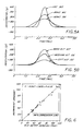
- Figs. 5a and 5b there is illustrated an aspect supporting the use of the two sets of signal channels 80, 82 of Fig. 4, and the manner in which the maintenance and combination of the two types of information serves to render the system insensitive to changes in force of the strike used to take any reading in a particular set. More particularly, Fig. 5a illustrates the accelerometer signal with respect to time under conditions of constant strike force but for materials of different hardness.
- a first curve 100 has a maximum deceleration peak well below 200g (representing a relatively soft material such as newsprint), an intermediate curve 102 peaked at slightly over 200g (representing material of intermediate hardness such as bond), and a third curve 103 sharply peaked above 300g (representing a harder material such as a highly calendered stock).
- the softer materials have deceleration characteristics which have broader bases, and that the harder materials provide not only higher peaks, but shorter deceleration times.
- Fig. 5b shows the response of material of a given hardness for strikes having different energies including a soft hit illustrated at 105, a medium hit at 106, and a hard hit at 107. It is seen that the contact duration for the three hits is about the same (primarily a function of material hardness), but that the value of the peak deceleration differs substantially, ranging from below 100g for the soft hit to approximately 300g for the hard hit. It will thus be appreciated that if hits of differing magnitudes such as illustrated in 5b were applied to the materials of differing hardness as illustrated in Fig. 5a, it would not be possible to readily distinguish (much less quantify) the hardness differences in the materials.
- the area under the curves of Fig. 5b is determined (in the channel 82 of Fig. 4) to provide a measure of the impact energy and thus allow the peak information from channel 80 to be normalized for impact energy, resulting in quantitative energy independent measure of relative roll hardness. Integrating the curves of Fig. 5b is equivalent to integrating an acceleration curve during the impact. Integration of the acceleration thus produces an output indicative of velocity, and such time integral produces what is known as the force impulse, a measure of the energy expended by the striker in impacting the roll.
- the channel 82 of the Fig. 4 circuitry integrates the signal produced by the accelerometer over time during the course of a strike, with the result being the integration of the strike impulse as shown in Fig. 5b. It will be appreciated that a comparatively smaller integrated magnitude will be produced with soft hits as exemplified by curve 105, whereas a substantially higher magnitude will be produced as a result of hard hits as exemplified by curve 107. It will also be appreciated that when the circuit is configured with a lower limit threshold (such as 100 millivolts) equivalent in one embodiment of the invention to an acceleration of 10g, no substantial error is introduced because of the symmetry of the curve and the resulting ability to make adjustments for such a threshold.
- a lower limit threshold such as 100 millivolts
- Fig. 6 is a graph illustrating roll meter readings on the Rho Meter (i.e., the meter readings from the prior accepted device illustrated in the '267 patent) vs. "instrument readings", i.e., readings made by a system as illustrated in Fig. 4 and exemplifying the present invention.
- the linear equation in the upper left-hand corner of the graph is the mathematical expression which relates instrument readings (y's) to Rho Meter readings (x's).
- the relationship is substantially linear with a value for R of about 0.99.
- the operator need only initiate each roll profile measurement sequence by depression of an appropriate pushbutton on the calculator 26.
- the operator then need only strike the roll at desired locations for the number of hits assigned to that profile.
- the system will continue to indicate to the operator (by flashing LED's, tones in the headset or otherwise), whether each reading is acceptable and whether any should be repeated.
- the operator will have sufficient information stored in the calculator device 26 relating to the profile of the entire roll, following which he can hit a reset button to initiate a data acquisition cycle for the next roll, and proceed as with the prior roll.
- a relatively unskilled operator can progress through a number of rolls of manufactured paper and return the calculator to the quality control department, where the data can be input into the standard quality control computer system for analysis and processing, providing data which is not only substantially more accurate than could be collected in the past, but which is also potentially greater in volume and in processability, allowing paper manufacturers previously unrealized opportunities to optimize the production process.
Landscapes
- Chemical & Material Sciences (AREA)
- Health & Medical Sciences (AREA)
- Life Sciences & Earth Sciences (AREA)
- General Health & Medical Sciences (AREA)
- Analytical Chemistry (AREA)
- Biochemistry (AREA)
- Physics & Mathematics (AREA)
- General Physics & Mathematics (AREA)
- Immunology (AREA)
- Pathology (AREA)
- Engineering & Computer Science (AREA)
- Food Science & Technology (AREA)
- Medicinal Chemistry (AREA)
- Investigating Strength Of Materials By Application Of Mechanical Stress (AREA)
- Lubrication Details And Ventilation Of Internal Combustion Engines (AREA)
Claims (17)
- Härtetester zum Bestimmen der relativen Härte eines Materials mit einer Schlagvorrichtung (36), die mit einer Kraft auf das Material aufschlägt, die in einem bestimmten Bereich variieren kann und welche ein Beschleunigungssignal abgibt, das vom Aufschlag abhängt, und mit ersten Mitteln (60, 62, 80, 84, 85) zum Erzeugen eines ersten Signals, das von der höchsten Verzögerung der Schlagvorrichtung (36) abhängt, dadurch gekennzeichnet, dass dieser in Kombination umfasst:
zweite Mittel (60, 62, 82, 87, 88) zum Erzeugen eines zweiten Signals, das von der Energie des Aufschlags der Schlagvorrichtung (36) abhängig ist, wobei das zweite Signal von der Kraft des bestimmten Aufschlags abhängig ist und
einem Computer (26a, 26b) zum Verarbeiten des ersten und zweiten Signals, wobei der Computer Information verwendet, die vom zweiten Signal abgeleitet ist, um das erste Signal zu korrigieren, wobei das Resultat dieser Korrelation ein Ausgangssignal ist, das die Grösse der relativen Härte darstellt und das angezeigt wird, wobei die Anzeige (44, 97, 98, 99) dieses Signals im wesentlichen unabhängig ist von der Kraft des Aufschlags. - Härtetester nach Anspruch 1, bei welchem der Computer (26a, 26b) weiter Mittel (90) zum Korrelieren der Grösse des Ausgangssignals mit Einheiten einer bestimmten Härteskala aufweist und mit einer Anzeige der Härte des Materials in diesen Einheiten.
- Härtetester nach Anspruch 2, bei welcher die Einheiten der vorbestimmten Härteskala Rho-Einheiten sind.
- Härtetester nach Anspruch 1, bei der die Schlagvorrichtung einen hammerförmigen Kopf (38) aufweist, der an einem Griff (32) befestigt ist, die eine hammerartige Vorrichtung bilden, die vom Bedienungspersonal wie ein gewöhnlicher Hammer gehandhabt werden kann.
- Härtetester nach Anspruch 4, bei welcher die Schlagvorrichtung (36) einen Beschleunigungsmesser (60) zum Erzeugen eines Beschleunigungssignals aufweist.
- Härtetester nach Anspruch 5, mit einer Schwellwerteinrichtung (84, 85) die dem Beschleunigungssignal zugeordnet ist und welche einen Schwellwert aufweist, wo die beim Schwingen der hammerartigen Vorrichtung entstehenden Signale unterhalb liegen, der aber beim Aufschlag überschritten wird.
- Härtetester nach Anspruch 1 mit einem Gehäuse (66), das angeordnet ist, um über das zu testende Material bewegt zu werden, mit Mitteln (64) zum Befestigen der Schlagvorrichtung (36) im Gehäuse (66), in einer Lage gegenüber dem Material und Mitteln (68, 69) welche die Schlagvorrichtung zum Aufschlagen auf das Material bringen, während das Gehäuse das Material überquert und dabei mehrere Messungen vornimmt.
- Härtetester nach Anspruch 1 bei welchem das Material die Form einer Rolle hat und die hammerartige Vorrichtung (22) ausgebildet ist, um in einer axialen Richtung der Rolle auf die Rolle aufzuschlagen.
- Verfahren zum Bestimmen der relativen Härte von gewickeltem Material unter Verwendung der Vorrichtung nach Anspruch 1, wobei eine Schlagvorrichtung (36) auf die Rolle aufschlägt mit einer Kraft, die in bestimmten Grenzen variieren kann und zum Bestimmen (60, 62, 80, 84, 85) der höchsten Verzögerung der Schlagvorrichtung beim Aufschlag, dadurch gekennzeichnet, dass dieses die Schritte umfasst:
Bestimmen (60, 62, 82, 87, 88) der Aufschlagkraft der Schlagvorrichtung,
Verknüpfen der Information (91) welche sich auf die Aufschlagkraft des Schlages und die höchste Verzögerung beim Aufschlag bezieht, um eine quantitative Messung der Härte des gewickelten Materials am Punkt des Aufschlags zu erhalten, und
die Härtewerte des gewickelten Materials anzuzeigen (94, 44, 96, 97, 98, 99). - Verfahren nach Anspruch 9, welches weiter die Schritte umfasst, die gemessene quantitative Härte des gewickelten Materials mit einer vorbestimmten Rho-Werteskala zu korrelieren (90) und die quantitative Härte des gewickelten Materials in Rho-Härtewerten dargestellt wird.
- Verfahren nach Anspruch 10, welches weiter den Schritt umfasst, an mehreren ausgewählten Punkten auf die Rolle aufzuschlagen, wobei die Schläge nicht mit der gleichen Kraft erfolgen müssen, und bei welchem vergleichbare Rho-Einheiten berechnet werden, die vergleichbar sind, weil die Unterschiede zwischen den Kräften der verschiedenen Schläge ausgeglichen werden.
- Verfahren nach Anspruch 9, bei welchem der Schritt des Aufschlagens weiter das Schwingen der hammerförmigen Sonde umfasst, derart, dass der hammerförmige Kopf der Sonde im wesentlichen senkrecht auf die Rollenoberfläche auftrifft.
- Verfahren nach Anspruch 9, der Schritt des Messens das Messen des Aufschlags mit dem Beschleunigungsmesser umfasst.
- Verfahren nach Anspruch 13, bei welchem der Schritt des Bestimmens der Energie des Aufschlags das Integrieren des Signals des Beschleunigungsmessers über die Zeit umfasst.
- Verfahren nach Anspruch 13, bei welchem das Bestimmen der Verzögerung das Erfassen des Verzögerungssignals des Beschleunigungsmessers umfasst.
- Verfahren nach Anspruch 14, bei welchem der Schritt des Bestimmens der Energie des Aufschlags weiter den Schritt umfasst, einen Schwellwert genügend hoch einzustellen, dass die Signale, die beim Schwingen der hammerförmigen Vorrichtung unterdrückt werden, aber genügend niedrig einzustellen, dass Signale vom Beschleunigungsmesser, die vom Aufschlag herrühren erfasst werden.
- Verfahren zur Profilaufnahme von Papierrollen mit den Schritten:a) Bereitstellen einer hammerförmigen Sonde, die einen Beschleunigungsmesser enthält,b) Schwingen der hammerförmigen Sonde um an einer vorbestimmten Stelle auf die Rolle zu schlagen und ein Sensorsignal zu erzeugen, das von der Verzögerung der Sonde abhängig ist,
gekennzeichnet durch die Schritte, ein weiteres Sensorsignal zu erzeugen, das von der Energie der Sonde beim Aufschlag auf die Rolle abhängt,c) Verarbeiten der entsprechenden Verzögerungs- und Energiesignale, um die vom Energiesignal abgeleitete Information zu verwenden, um das Verzögerungssignal zu korrigieren und eine quantitative Messung der Härte der Rolle am Punkt des Aufschlags zu erzeugen, die im wesentlichen von der Kraft des Aufschlags unabhängig ist,d) dem Bedienungspersonal anzuzeigen, ob die Signale vom erzeugten Aufschlag brauchbar oder unbrauchbar waren um einen Punkt im Profil zu erhalten, mit dem entspechenden Aufschlag,e) die Schritte b - d beim letzten Punkt des Aufschlags zu wiederholen, wenn die Messung unbrauchbar war,f) die Ergebnisse der Messung der Rollenhärte für den Aufschlag an einem Punkt zu speichern, wenn die Messung akzeptiert wurde, undg) die Schritte b - f bei weiteren Aufschlagspunkten zu wiederholen, um ein automatisch gespeichertes Rollenprofil zu bestimmen indem mit der Sonde entlang der Länge der Rolle auf diese geklopft wird.
Applications Claiming Priority (3)
| Application Number | Priority Date | Filing Date | Title |
|---|---|---|---|
| US07/472,780 US5079728A (en) | 1990-01-31 | 1990-01-31 | Method and apparatus for quantitatively evaluating roll hardness |
| PCT/US1991/000096 WO1991011698A1 (en) | 1990-01-31 | 1991-01-10 | Method and apparatus for quantitatively evaluating roll hardness |
| US472780 | 1995-06-07 |
Publications (2)
| Publication Number | Publication Date |
|---|---|
| EP0513144A1 EP0513144A1 (de) | 1992-11-19 |
| EP0513144B1 true EP0513144B1 (de) | 1994-08-24 |
Family
ID=23876918
Family Applications (1)
| Application Number | Title | Priority Date | Filing Date |
|---|---|---|---|
| EP91903742A Expired - Lifetime EP0513144B1 (de) | 1990-01-31 | 1991-01-10 | Verfahren und vorrichtung zur quantitativen bestimmung der härte einer rolle |
Country Status (11)
| Country | Link |
|---|---|
| US (1) | US5079728A (de) |
| EP (1) | EP0513144B1 (de) |
| JP (1) | JPH07119675B2 (de) |
| KR (1) | KR0163565B1 (de) |
| CN (1) | CN1029259C (de) |
| BR (1) | BR9105960A (de) |
| CA (1) | CA2074934C (de) |
| DE (2) | DE513144T1 (de) |
| FI (1) | FI101903B1 (de) |
| RU (1) | RU2100794C1 (de) |
| WO (1) | WO1991011698A1 (de) |
Families Citing this family (31)
| Publication number | Priority date | Publication date | Assignee | Title |
|---|---|---|---|---|
| US5227988A (en) * | 1989-11-09 | 1993-07-13 | Nippon Steel Corporation | Apparatus for detecting various process values and apparatus for recording information |
| US5282382A (en) * | 1991-09-16 | 1994-02-01 | Champion International Corporation | Roll hardness observation testing apparatus and process |
| US5423241A (en) * | 1992-10-05 | 1995-06-13 | Rensselaer Polytechnic Institute | Quantitative method for evaluation of the state of piano hammer felt tonal regulation |
| US5804707A (en) * | 1992-10-05 | 1998-09-08 | Rensselaer Polytechnic Institute | Dynamic hardness testing using measurement of the scarton dynamic hardness (SDH) |
| US5402673A (en) * | 1994-05-18 | 1995-04-04 | James River Paper Company, Inc. | System for testing firmness of a paper roll |
| AU3355397A (en) * | 1996-07-18 | 1998-02-10 | Proceq S.A. | Method and device for characterizing the elastic and/or plastic behaviour of materials |
| US5825672A (en) * | 1996-10-25 | 1998-10-20 | The United States Of America As Represented By The United States Department Of Energy | Method and apparatus for automatically detecting patterns in digital point-ordered signals |
| US6354148B2 (en) | 1997-02-28 | 2002-03-12 | Kabushiki Kaisha Akashi | Rebound-type hardness tester |
| US6186400B1 (en) * | 1998-03-20 | 2001-02-13 | Symbol Technologies, Inc. | Bar code reader with an integrated scanning component module mountable on printed circuit board |
| RU2151385C1 (ru) * | 1998-05-12 | 2000-06-20 | Открытое акционерное общество "Абразивы и шлифование" | Устройство для определения твердости и других физико-механических свойств абразивных изделий |
| DE19904448A1 (de) * | 1999-02-04 | 2000-08-24 | Murat Bajozitovic Bakirov | Verfahren zur zerstörungsfreien Ermittlung mechanischer Eigenschaften von Objektbereichen |
| DE10027145A1 (de) * | 2000-05-23 | 2001-12-06 | Mcm Pruefsysteme Gmbh Measurem | Verfahren und Anordnung zur Qualitätsprüfung von mechanischen Bauteilen |
| US20030167845A1 (en) * | 2001-07-10 | 2003-09-11 | Stefan Maetschke | Defect identification in bodies consisting of brittle material |
| ES2192948B2 (es) * | 2001-07-20 | 2005-10-16 | Universidad Politecnica De Madrid | Sensor de firmeza de frutos por impacto. |
| US20040015116A1 (en) * | 2002-07-22 | 2004-01-22 | Handforth Charles Adrian | Firm-contact apparel prosthesis for tremor suppression and method of use thereof |
| US7127951B2 (en) * | 2003-11-07 | 2006-10-31 | Kimberly-Clark Worldwide, Inc. | Roll firmness measuring system and process |
| CZ20041081A3 (cs) * | 2004-11-01 | 2006-06-14 | Výzkumný ústav textilních stroju Liberec a. s. | Zpusob merení tvrdosti a/nebo hustoty prízových návinu a zarízení k jeho provádení |
| US7104031B2 (en) * | 2004-12-20 | 2006-09-12 | Kimberly-Clark Worldwide, Inc. | Variable position constant force packaging system and process for using same |
| EP1893973B1 (de) * | 2005-06-24 | 2010-06-23 | Marco Brandestini | Vorrichtung zur härtemessung mittels aufprall |
| FR2898890B1 (fr) * | 2006-03-23 | 2008-05-09 | Saint Gobain Ct Recherches | Produit d'oxyde d'yttrium fritte et dope. |
| AT504851B1 (de) * | 2006-11-07 | 2009-03-15 | Arc Seibersdorf Res Gmbh | Schlagpolster |
| JP5798732B2 (ja) * | 2010-10-20 | 2015-10-21 | 日本製紙株式会社 | オフセット輪転印刷機用新聞巻取紙とその製造方法 |
| US20150128686A1 (en) * | 2013-11-13 | 2015-05-14 | Denis Gloede | Hardness tester apparatus |
| US10426541B2 (en) * | 2014-04-02 | 2019-10-01 | Centre National De La Recherche Scientifique (Cnrs) | Device for assisting with the placement of an orthopedic instrument |
| WO2017210464A1 (en) * | 2016-06-01 | 2017-12-07 | The Board Of Regents For Oklahoma State University | Wound roll quality instrument and method |
| FR3071719B1 (fr) * | 2017-09-29 | 2022-06-03 | Centre Nat Rech Scient | Dispositif d'insertion d'un implant chirurgical |
| JP7181515B2 (ja) * | 2017-11-09 | 2022-12-01 | 大王製紙株式会社 | ティシュペーパー及びティシュペーパーの評価方法 |
| WO2019230687A1 (ja) * | 2018-05-28 | 2019-12-05 | パナソニックIpマネジメント株式会社 | 打音検査端末、打音検査システムおよび打音検査データ登録方法 |
| CN109883862B (zh) * | 2019-03-29 | 2024-04-05 | 巨石集团有限公司 | 一种纱团硬度测量仪及其测量方法 |
| JP7720134B2 (ja) | 2019-04-22 | 2025-08-07 | 住友化学株式会社 | 樹脂フィルムロールの製造方法 |
| CN113390741A (zh) * | 2020-03-13 | 2021-09-14 | 中核苏阀科技实业股份有限公司 | 一种间接检测闸阀闸板成品密封面真实硬度的方法 |
Family Cites Families (14)
| Publication number | Priority date | Publication date | Assignee | Title |
|---|---|---|---|---|
| FR1001230A (fr) * | 1946-03-29 | 1952-02-21 | Perfectionnements apportés aux appareils de mesure à rebondissement, notamment à ceux pour la détermination de la dureté d'une pièce | |
| US2737048A (en) * | 1953-01-12 | 1956-03-06 | John W T Van Erp | Materials testing device |
| US2834202A (en) * | 1955-06-27 | 1958-05-13 | Gen Electric | Apparatus for measuring hardness |
| US3425267A (en) * | 1965-12-13 | 1969-02-04 | Beloit Eastern Corp | Hardness tester |
| US3425263A (en) * | 1967-03-06 | 1969-02-04 | Gen Electric | Apparatus for measuring some mechanical properties of a material |
| US3540270A (en) * | 1969-01-16 | 1970-11-17 | Westvaco Corp | Reel hardness tester |
| US3822588A (en) * | 1970-11-02 | 1974-07-09 | R Knight | Apparatus for measuring the hardness of material |
| US3759085A (en) * | 1971-03-04 | 1973-09-18 | Massachusetts Inst Technology | Impact sensor and coder apparatus |
| US3879982A (en) * | 1972-10-16 | 1975-04-29 | Ernst Schmidt | Method and apparatus for testing hardness of specimens |
| US4034603A (en) * | 1974-11-07 | 1977-07-12 | Proceq Sa | Method of an apparatus for testing the hardness of materials |
| EP0076864B1 (de) * | 1981-04-20 | 1986-08-27 | Mitsubishi Denki Kabushiki Kaisha | Schlagprüfgerät |
| GB8309030D0 (en) * | 1983-03-31 | 1983-05-11 | Cawley P | Testing of structures by impact |
| US4615209A (en) * | 1985-01-03 | 1986-10-07 | Change Jr Nicholas D | Multi range impulse hammer |
| US4856318A (en) * | 1987-07-20 | 1989-08-15 | Playground Clearing House, Inc. | Surface resiliency tester |
-
1990
- 1990-01-31 US US07/472,780 patent/US5079728A/en not_active Expired - Fee Related
-
1991
- 1991-01-10 CA CA002074934A patent/CA2074934C/en not_active Expired - Fee Related
- 1991-01-10 RU SU925052790A patent/RU2100794C1/ru active
- 1991-01-10 DE DE199191903742T patent/DE513144T1/de active Pending
- 1991-01-10 EP EP91903742A patent/EP0513144B1/de not_active Expired - Lifetime
- 1991-01-10 JP JP3503545A patent/JPH07119675B2/ja not_active Expired - Lifetime
- 1991-01-10 BR BR919105960A patent/BR9105960A/pt not_active IP Right Cessation
- 1991-01-10 DE DE69103622T patent/DE69103622T2/de not_active Expired - Fee Related
- 1991-01-10 WO PCT/US1991/000096 patent/WO1991011698A1/en not_active Ceased
- 1991-01-10 KR KR1019920701820A patent/KR0163565B1/ko not_active Expired - Fee Related
- 1991-01-17 CN CN91100378A patent/CN1029259C/zh not_active Expired - Fee Related
-
1992
- 1992-07-30 FI FI923442A patent/FI101903B1/fi active
Also Published As
| Publication number | Publication date |
|---|---|
| DE513144T1 (de) | 1993-07-08 |
| BR9105960A (pt) | 1992-10-13 |
| CA2074934C (en) | 1994-11-08 |
| JPH07119675B2 (ja) | 1995-12-20 |
| FI101903B (fi) | 1998-09-15 |
| WO1991011698A1 (en) | 1991-08-08 |
| CA2074934A1 (en) | 1991-08-01 |
| EP0513144A1 (de) | 1992-11-19 |
| DE69103622D1 (de) | 1994-09-29 |
| FI923442A7 (fi) | 1992-07-30 |
| KR920704116A (ko) | 1992-12-19 |
| FI923442A0 (fi) | 1992-07-30 |
| KR0163565B1 (ko) | 1999-03-30 |
| CN1053840A (zh) | 1991-08-14 |
| JPH05504198A (ja) | 1993-07-01 |
| CN1029259C (zh) | 1995-07-05 |
| DE69103622T2 (de) | 1995-03-02 |
| FI101903B1 (fi) | 1998-09-15 |
| US5079728A (en) | 1992-01-07 |
| RU2100794C1 (ru) | 1997-12-27 |
Similar Documents
| Publication | Publication Date | Title |
|---|---|---|
| EP0513144B1 (de) | Verfahren und vorrichtung zur quantitativen bestimmung der härte einer rolle | |
| US6206837B1 (en) | Portable system with telemetric data transmission for the measurement of metabolic parameters | |
| US5757266A (en) | Electronic apparatus for providing player performance feedback | |
| CA2380988C (en) | Log testing apparatus | |
| GB2364127B (en) | Method and apparatus for monitoring structural fatigue and use | |
| CN1003540B (zh) | 蒸汽泄漏量测定装置 | |
| KR20080114159A (ko) | 초음파를 이용한 콘크리트 강도측정 장치 및 방법 | |
| WO2004033032A3 (en) | Connection verification apparatus, system, and method | |
| US5438351A (en) | Vacuum priming diagnostic cartridge | |
| US5282382A (en) | Roll hardness observation testing apparatus and process | |
| CN111238933B (zh) | 毛巾柔软度测试方法和测试装置 | |
| CA1329954C (en) | Electronic shock absorber testing instrument | |
| JP2920900B2 (ja) | 配管内部診断装置 | |
| CN213813224U (zh) | 一种便携式橡胶回弹性测试仪 | |
| KR101111982B1 (ko) | 셔틀런 측정 시스템 | |
| JPH09251006A (ja) | 携帯型強度判定装置 | |
| KR200187968Y1 (ko) | 기억(Memory)장치겸용 가시광선 투과율 측정기 | |
| CN221630911U (zh) | 一种测力计 | |
| CN112162067B (zh) | 一种用于测量烟草填充值测定仪保压时间的检测装置及方法 | |
| US20150128686A1 (en) | Hardness tester apparatus | |
| JP3162304B2 (ja) | スイッチ動作力測定装置 | |
| KR200269587Y1 (ko) | 기초 체력 측정 장치 및 방법 | |
| KR20110053763A (ko) | 중. 단거리 달리기 자동 측정기 제조장치 | |
| EP1653212A2 (de) | Verfahren zur Härte- bzw. Dichtheitsmessung von Garnpaketen und eine Vorrichtung zur Verfahrensdurchführung | |
| JP3437469B2 (ja) | 振動センサ |
Legal Events
| Date | Code | Title | Description |
|---|---|---|---|
| PUAI | Public reference made under article 153(3) epc to a published international application that has entered the european phase |
Free format text: ORIGINAL CODE: 0009012 |
|
| 17P | Request for examination filed |
Effective date: 19920717 |
|
| AK | Designated contracting states |
Kind code of ref document: A1 Designated state(s): CH DE FR GB IT LI SE |
|
| ITCL | It: translation for ep claims filed |
Representative=s name: RICCARDI SERGIO & CO. |
|
| EL | Fr: translation of claims filed | ||
| 17Q | First examination report despatched |
Effective date: 19930519 |
|
| DET | De: translation of patent claims | ||
| RIN1 | Information on inventor provided before grant (corrected) |
Inventor name: OLIVER, WILLIAM, K. Inventor name: ROISUM, DAVID, R. Inventor name: BAUM, SCOTT, A. Inventor name: ADAMS, RICHARD, J. |
|
| GRAA | (expected) grant |
Free format text: ORIGINAL CODE: 0009210 |
|
| AK | Designated contracting states |
Kind code of ref document: B1 Designated state(s): CH DE FR GB IT LI SE |
|
| REF | Corresponds to: |
Ref document number: 69103622 Country of ref document: DE Date of ref document: 19940929 |
|
| ITF | It: translation for a ep patent filed | ||
| ET | Fr: translation filed | ||
| EAL | Se: european patent in force in sweden |
Ref document number: 91903742.4 |
|
| PLBE | No opposition filed within time limit |
Free format text: ORIGINAL CODE: 0009261 |
|
| STAA | Information on the status of an ep patent application or granted ep patent |
Free format text: STATUS: NO OPPOSITION FILED WITHIN TIME LIMIT |
|
| 26N | No opposition filed | ||
| PGFP | Annual fee paid to national office [announced via postgrant information from national office to epo] |
Ref country code: GB Payment date: 19981211 Year of fee payment: 9 |
|
| PGFP | Annual fee paid to national office [announced via postgrant information from national office to epo] |
Ref country code: FR Payment date: 19981215 Year of fee payment: 9 |
|
| PGFP | Annual fee paid to national office [announced via postgrant information from national office to epo] |
Ref country code: SE Payment date: 19981223 Year of fee payment: 9 |
|
| PGFP | Annual fee paid to national office [announced via postgrant information from national office to epo] |
Ref country code: CH Payment date: 19981229 Year of fee payment: 9 |
|
| PG25 | Lapsed in a contracting state [announced via postgrant information from national office to epo] |
Ref country code: GB Free format text: LAPSE BECAUSE OF NON-PAYMENT OF DUE FEES Effective date: 20000110 |
|
| PG25 | Lapsed in a contracting state [announced via postgrant information from national office to epo] |
Ref country code: SE Free format text: LAPSE BECAUSE OF NON-PAYMENT OF DUE FEES Effective date: 20000111 |
|
| PG25 | Lapsed in a contracting state [announced via postgrant information from national office to epo] |
Ref country code: LI Free format text: LAPSE BECAUSE OF NON-PAYMENT OF DUE FEES Effective date: 20000131 Ref country code: CH Free format text: LAPSE BECAUSE OF NON-PAYMENT OF DUE FEES Effective date: 20000131 |
|
| GBPC | Gb: european patent ceased through non-payment of renewal fee |
Effective date: 20000110 |
|
| EUG | Se: european patent has lapsed |
Ref document number: 91903742.4 |
|
| REG | Reference to a national code |
Ref country code: CH Ref legal event code: PL |
|
| PG25 | Lapsed in a contracting state [announced via postgrant information from national office to epo] |
Ref country code: FR Free format text: LAPSE BECAUSE OF NON-PAYMENT OF DUE FEES Effective date: 20000929 |
|
| REG | Reference to a national code |
Ref country code: FR Ref legal event code: ST |
|
| PG25 | Lapsed in a contracting state [announced via postgrant information from national office to epo] |
Ref country code: IT Free format text: LAPSE BECAUSE OF NON-PAYMENT OF DUE FEES;WARNING: LAPSES OF ITALIAN PATENTS WITH EFFECTIVE DATE BEFORE 2007 MAY HAVE OCCURRED AT ANY TIME BEFORE 2007. THE CORRECT EFFECTIVE DATE MAY BE DIFFERENT FROM THE ONE RECORDED. Effective date: 20050110 |
|
| PGFP | Annual fee paid to national office [announced via postgrant information from national office to epo] |
Ref country code: DE Payment date: 20070110 Year of fee payment: 17 |
|
| PG25 | Lapsed in a contracting state [announced via postgrant information from national office to epo] |
Ref country code: DE Free format text: LAPSE BECAUSE OF NON-PAYMENT OF DUE FEES Effective date: 20080801 |