EP0514012A2 - Verfahren und Vorrichtung zur Umsetzung der Norm eines Bildsignals - Google Patents
Verfahren und Vorrichtung zur Umsetzung der Norm eines Bildsignals Download PDFInfo
- Publication number
- EP0514012A2 EP0514012A2 EP92303406A EP92303406A EP0514012A2 EP 0514012 A2 EP0514012 A2 EP 0514012A2 EP 92303406 A EP92303406 A EP 92303406A EP 92303406 A EP92303406 A EP 92303406A EP 0514012 A2 EP0514012 A2 EP 0514012A2
- Authority
- EP
- European Patent Office
- Prior art keywords
- storage means
- frames
- images
- fields
- image
- Prior art date
- Legal status (The legal status is an assumption and is not a legal conclusion. Google has not performed a legal analysis and makes no representation as to the accuracy of the status listed.)
- Withdrawn
Links
Images





Classifications
-
- H—ELECTRICITY
- H04—ELECTRIC COMMUNICATION TECHNIQUE
- H04N—PICTORIAL COMMUNICATION, e.g. TELEVISION
- H04N7/00—Television systems
- H04N7/01—Conversion of standards, e.g. involving analogue television standards or digital television standards processed at pixel level
- H04N7/0135—Conversion of standards, e.g. involving analogue television standards or digital television standards processed at pixel level involving interpolation processes
- H04N7/014—Conversion of standards, e.g. involving analogue television standards or digital television standards processed at pixel level involving interpolation processes involving the use of motion vectors
-
- H—ELECTRICITY
- H04—ELECTRIC COMMUNICATION TECHNIQUE
- H04N—PICTORIAL COMMUNICATION, e.g. TELEVISION
- H04N7/00—Television systems
- H04N7/01—Conversion of standards, e.g. involving analogue television standards or digital television standards processed at pixel level
- H04N7/0112—Conversion of standards, e.g. involving analogue television standards or digital television standards processed at pixel level one of the standards corresponding to a cinematograph film standard
-
- Y—GENERAL TAGGING OF NEW TECHNOLOGICAL DEVELOPMENTS; GENERAL TAGGING OF CROSS-SECTIONAL TECHNOLOGIES SPANNING OVER SEVERAL SECTIONS OF THE IPC; TECHNICAL SUBJECTS COVERED BY FORMER USPC CROSS-REFERENCE ART COLLECTIONS [XRACs] AND DIGESTS
- Y10—TECHNICAL SUBJECTS COVERED BY FORMER USPC
- Y10S—TECHNICAL SUBJECTS COVERED BY FORMER USPC CROSS-REFERENCE ART COLLECTIONS [XRACs] AND DIGESTS
- Y10S348/00—Television
- Y10S348/911—Line doubler adapted for reproducing programme originally from film, e.g. 24 frames per second
Definitions
- the present invention relates to an apparatus for and method of image translation and in particular to, but not exclusively to, high resolution transfer of images from film to video and vice versa or from one T.V. standard to another where the images originated on film.
- images are recorded on film. Each image is a single photographic exposure so that all parts of the image correspond to roughly the same point in time. Typically, but not always, images are captured on film at an exposure rate of 24 frames per second.
- images can be stored not only on film but also directly as an electronic video signal. It is not uncommon for television programmes to have some of the images recorded on film and some recorded as a video signal.
- Images when represented as a video signal comprise a number of orthogonal scanning lines formed by scanning the image from left to right and top to bottom as the scene is viewed. Consequently, the lower right hand parts of any image are scanned at a later point in time than the upper left hand parts.
- Each of the scanning lines contains luminance (brightness) or chrominance (colour) information for the image.
- each image or frame For each image or frame, the video electronic signal scans twice: a single scan is called a field.
- each image or frame comprises two video fields and each video field contains half the lines of an image or frame.
- the lines of the first field overlap the lines of the second field such that the lines are vertically off-set by half a line height so that each line of the second field lies between the lines of the first field.
- This technique is known as interlacing.
- the images are captured at a particular frame rate. Due to the history of television, different parts of the world have adopted different frame rates. The two most common frame rates are 25 frames per second or 50 video fields per second comprising 625 lines per image which is most prevalent in the UK and parts of Europe and substantially 30 frames per second, that is to say approximately 60 video fields per second comprising 525 lines per image and is most prevalent in North America.
- PAL Phase Alternate Line
- NTSC National Television Standards Committee
- Television is a complex sampling process. That is to say, the image is sampled temporally at the PAL or NTSC standard so that each point or location in the image is regularly sampled at the relevant frequency. Each image is then sampled vertically by the scan lines progressing from the top to the bottom of the screen using the line structure. If the signal is to be processed digitally it will be further sampled horizontally on a pixel basis resulting in a three dimensionally sampled signal. Standards conversion is thus the process of transferring the signal from one or more of these sample rates to another.
- interpolating Creating one sequence of regular samples from another is known as interpolating, and is a quite well understood form of digital filtering. For further reference information on interpolating, one can find relevant details in BBC Research Department Report No 1984/20 or UDC 621.397.65.
- each sample at the new sample points is calculated by summing weighted contributions from the nearest input samples. How many input samples need to be used, and the relative weightings to be applied to them, are decisions made by the designer, and govern the compromise between cost, complexity and performance.
- the overall family of weighting factors is known as the 'aperture' of the filter since it represents the window of input samples which are used to create each output sample.
- the aperture should have a minium width of four field lines and four fields. This means that every output line is made up from weighted contributions from the four nearest lines on the four nearest fields, making 16 in all.
- the relevant weights, or filter coefficients depend on the relative position of the output line with respect to the input lines and field timing. This is shown diagrammatically in figure 3.
- a motion detector is used to determine if there have been any editing cuts so as to disturb the field sequence.
- the motion detector does not however provide information on any moving objects so as to improve the resolution of the conversion.
- Aliassing is a type of distortion and juddering is the visual effect of aliassing.
- Aliassing is caused by a sampled signal containing frequencies above one half of the sampling frequency. This results in erroneous frequencies appearing in the signal which are indistinguishable from the same frequencies had they been in the original: hence the term aliassing.
- a temporally sampled signal such as television
- the erroneous frequencies result in the irregular motion of objects, which, unless indistinct due to blurring, will appear to judder.
- a motion vector describes the motion of all or part of an image. It represents both the direction and scale of the motion.
- motion compensation which uses these motion vectors.
- a basic diagram of such a motion compensator as applied to the input video signal can be found in figure 4.
- motion compensation please refer to Shimano et al. 1989. - Movement Compensated TV Standards Converter using motion vectors, SMPTE Proceedings 1989. The resolution from such motion compensation is, however, highly unsatisfactory.
- the problem sought to be overcome by the present invention is to accommodate for objects moving in an image when converting from film to one of the TV standards or when converting between TV standards when part or all of the image originates on film.
- no techniques have been known to make allowances for moving objects.
- the two stages of conversion introduce and compound the distortions.
- standard converters with some form of motion compensation are known. Such standards converters are not able to provide high resolution when some of the images originate from film. Furthermore, such conversion has hitherto badly accommodated for the intermediate video tape being edited and thus disturbing the field sequence.
- an aim of the present invention is to provide an apparatus for and method of image translation when at least part of which originates on film and which has a higher resolution than known to date.
- an apparatus for translating images at least part of which were originally stored on film said images being represented by an electronic input signal having a number of input frames of a first frequency and being translated to an electronic output signal having a number of output frames of a second frequency
- said apparatus comprising; means for converting said input signal to the output signal, said converting means including a number of storage means each for storing a field of the input signal; an address generator for controlling the or each of the storage means; an interpolator coupled to the or each of the storage means for filtering the fields of the input signal having been stored in the storage means to derive the output signal; characteriseri by: a motion estimator for providing motion vectors of any objects moving in the image, said motion estimator is coupled to said address generator for manipulating the read or write addresses and is coupled to the interpolator for manipulating the filtering thereby to compensate for movement of objects in the image.
- a Standards Converter for converting images between one TV standard to another in which at least a part of the images were originally stored on film, said images being represented by an input signal having a number of input frames in the input TV standard and being translated to an output signal having a number of output frames in the output TV standard
- said Standards Converter comprising; a number of storage means each for storing a field of the input signal; an address generator for controlling the or each of the storage means; an interpolator coupled to the or each of the storage means for filtering the fields of the input signal having been stored in the storage means to derive the output signal; characterised by: a motion estimator for providing motion vectors of any objects moving in the image, said motion estimator is coupled to said address generator for manipulating the read or write addresses and is coupled to the interpolator for manipulating the filtering thereby to compensate for movement of objects in the image.
- a telecine for translating images originally captured on film to a video signal, in which said images are represented by an electronic input signal having a number of input frames of a first frequency and being translated to said video output signal having a number of output frames of a second frequency
- said telecine comprising; means for converting said input signal to the output signal, said converting means including a number of storage means each for storing a field of the input signal; an address generator for controlling the or each of the storage means; an interpolator coupled to the or each of the storage means for filtering the fields of the input signal having been stored in the storage means to derive the output signal; characterised by: a motion estimator for providing motion vectors of any objects moving in the image, said motion estimator is coupled to said address generator for manipulating the read or write addresses and is coupled to the interpolator for manipulating the filtering thereby to compensate for movement of objects in the image.
- a method of translating images at least part of which were originally stored on film said images being represented by an electronic input signal having a number of input frames of a first frequency and being translated to an electronic output signal having a number of output frames of a second frequency
- said method comprising; converting said input signal to the output signal including storing one or more fields of the input signal each in a respective storage means and interpolating across the or each field of the input signal having being stored in the respective storage means, characterised by generating motion vectors of any objects moving in the image and manipulating the storage and interpolation steps using said motion vectors to compensate for objects moving in the image.
- the present invention is directed towards an apparatus for and method of image translation when part of the image originates on film providing high resolution particularly where there are moving objects in the image. This is achieved by utilizing known motion vectors in a novel manner so as to compensate for objects moving in the image.
- Such high resolution of moving images has become increasingly more important with the introduction of high definition television systems.
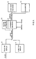
- Figure 5 illustrates the preferred embodiment of the present invention.
- the preferred embodiment may be used to convert images orignally stored on film to a video electronic signal of either of the most common standards or from one standard to another.
- the output could be stored as another video standard or transmitted directly.
- a telecine In order to convert images originally stored on film it is first converted to a video electronic signal at a frame rate of 24 frames per second by an apparatus 2 known as a telecine. Some known telecines, rather than generating a video signal of sequential fields, generate a video signal of each frame. This video signal of each frame is then stored in a memory known as a frame store. When reading from the frame store, alternate lines are read to create the two sequential fields for each frame as in a normal video signal. Alternatively, the preferred embodiment may be used to convert a video electronic signal by replaying a video tape replay 4 which can be switched between PAL at 50 Hz or NTSC at 60Hz.
- the standards converter 8 is usually used to convert from one television standard to another but when converting from film to video it may not be required to change the field or line frequencies.
- the conversion is controlled by timing information from the input and output signal.
- the input and output signals each contain information regarding the start and end of the frame, fields and lines. It is this information which is used to control the standards converter 8.
- a further control is also applied to the standards converter 8 to dictate what conversion frequencies are relevant for any particular conversion.
- a vector motion estimator 10 receives the input video signal to analyse the motion in the image.
- the vector motion estimator is coupled to the standards converter providing motion vectors to compensate for moving objects in the image.
- the converted images are then output to a video tape recorder 12 or directly transmitted via a transmitter 14.
- the preferred embodiment of the present invention is illustrated in more detail in figure 6. From this diagram, one can clearly identify the input video signal being applied to both the standards converter 8 and the vector motion estimator 10.
- the standards converter 8 comprises a memory of N stores 161 to N where N is an integer and typically equals 4. Thus, if each store 16 holds one field of video information, the memory at any one time stores four fields of the electronic video signal.
- each store 16 comprises a random access memory (RAM)
- Each store 16 is designed to hold one field of video information from the video electronic signal.
- An address generator (18) controls the storing of such video information by controlling the read and write address sent to the stores 16. Again the timing information from the input and output signals is supplied to the address generator 18 to control the fields being stored in the stores 16 by way of the read and write addresses.
- the standards converter 8 includes an interpolator 20.
- the interpolator 20 receives timing information of the input video signal to generator a set of coefficients. Details of the interpolation are not significant to the present invention and various methods can be used.
- the coefficients 1 to N from the interpolator 20 are used to control the relative weighting of the output signals from each store 161 to N. When converting from one standard to another, this enables lines to be created where no lines existed previously from the adjacent four field lines over four fields. All the weighted contributions are then summed to provide the video output signal. As shown in figure 6, this is achieved by N multiplers 22 each coupled to an adder 24. However, alternative arrangements are envisaged such as the use of a multipler and summer for each stage arranged in a cascade.
- the conversion is a sequentially sampling process
- 4 fields are initially stored and interpolated and then the successive 4 fields are stored and interpolated. That is to say, the first 4 fields a to d are supplied and then b to e and then c to f and so on.
- the details of the motion estimator 10 are not significant to the present invention. However, details can be found in many articles, for example BBC Research Department Report (No. RD 1987/11 or UDC 621.39.3).
- Many vector motion estimators can provide motion information to a resolution to at least as fine as a signal picture element or pixel. If the resolution is better than a single pixel and it is expected that with increasing development work on vector motion estimators then such better resolution will be obtainable, then the standards converter 8 can use such sub-pixel data.
- the vector motion estimator 10 is coupled directly to the input video signal.
- the output of the vector motion estimator 10 is directly coupled to the address generator 18 and interpolator 20 of the standards converter 8.
- the vector motion estimator 10 is coupled to the address generator 18 to provide motion vectors so as to compensate for moving objects in the image. This can be achieved in two ways both of which involve manipulation of the read or write addresses.
- the first way involves the address generator 18 assigning each pixel of the input video signal to the corresponding element in the store.
- the motion vectors are used to anticipate where the object has moved with respect to the image on successive or adjacent fields and provides read information to the location in the successive or adjacent store where the object is now stored.
- the vector motion estimator 10 has identified an object in the first video field in location A.
- the address generator 18 stored the object in its corresponding location A in store 161.
- the vector motion estimator 10 provides a motion vector giving the scale and direction of movement to the address generator 18.
- a new read address is generated from the motion vector so that on the successive store 162 the image is read from location B which is the location the vector motion estimator 10 anticipates the image to move to.
- the alternative method is for the motion vectors to manipulate the write address of the address generator 18. This enables a moving object to be stored in the first field in the location where the object has moved to in the successive field.
- the vector motion estimator 10 detects an object which is moving and which should be stored in store 161 at location A. However, through manipulation of the write address, the object is stored at location B which is the location the object moves to in the next field which is stored in store 162.
- the read addresses for the first field are not manipulated as the moving object is already in the same location as the next field.
- the information relating to the moving object is taken from each of the four fields for suitable weighting to provide requisite information for the output video signal.
- the vector motion esimator 10 is also coupled to the interpolator 20.
- the motion vectors provided to the interpolator 20 enable the coefficients to be modified so as to alter the particular weight applied to each of the output signals from the stores 16. Since the vertical addressing of each field store may be changed by the motion vectors by a non-integral number of field lines, so the aperature coefficients used by the interpolator also need to be modified by the motion vectors. Thus, the video signal of a moving object can be correctly filtered even if the scanning lines have changed.
- the motion vectors are used to manipulate not only the location of storage of a moving object but also the weight applied to it.
- FIG 7 An object in constant motion over four field is shown in figure 7.
- the direction of motion shown as down in the drawing, can be any direction in the real scene.
- Each of the four fields, F--, F-, F+ and F++ represent a field on the input video signal and the small square is the object moving a constant amount, V, during each field interval.
- V the object moving a constant amount
- the output field will generally be at some point between two input fields. In figure 7 this is shown by the broken line, T, and the inter-field spacing is shown by ⁇ .
- T the broken line
- ⁇ the inter-field spacing
- ⁇ varies between 0 and 1 according to the timing of the output field T, with respect to the two nearest input fields F- and F+ in figure 7.
- the images of a moving object obtained from the four stores can be aligned to the nearest pixel. Subsequent interpolation carried out over the four fields will then occur between images which are spatially coincident to an accuracy limited by the accuracy of the compensation system.
- the relative coefficient weighting applied to the four fields can be made dependant on ⁇ to give an appropriate temporal response. The effect of positional errors in the compensation system is reduced by the temporal filtering imposed by the interpolating aperture.
- motion compensation can be applied when translating images from one medium to another or from one standard to another.
- the present invention will now be described with reference to those particular conversions.
- the motion should be measured over a frame period or possibly over a field period and stored for one field.
- the former is preferred because ot simpler control, and similarities in handling of the vectors. Note that in either case the actual measured vector is still the motion over a frame period, and is thus double that described earlier and used in normal standards conversion.
- timing of the output field corresponds to a time between two input fields which have been derived from the same field frame then these two fields are co-sited.
- output field is timed between two fields from differing film frames when they are non-co-sited.
- ⁇ In a direct 25fr/s film to 50Hz video transfer ⁇ will be generally constant although, it will in fact vary slowly if the converter is synchronising the signal between two slightly different scanning references. However, to allow for the conversion from 24fr/s film to 50Hz video, ⁇ must be allowed to take a range of values.
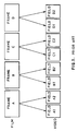
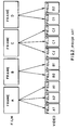
- the preferred embodiment is also applied when converting film to the NTSC standard at 30 frames per second. This is more complex than converting to the PAL standard and is usually done by 3:2 conversion as discussed previously and as shown in figure 2. In this case, alternate frames A, C have a repeated field. Again, duplication of fields means that the same fields are at the same point in time which is unlike direct video signal and introduces errors with moving objects.
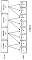
- each output field is derived from three of the input frames as shown in figure 14. As the contribution from each input frame is motion compensated, the resolution of the output video signal is vastly improved. It should be noted that it is not important that three frames contribute to each output field and indeed the number of frames may vary according to the accuracy required from the motion estimation process.
- the motion estimator 10 detects the correct phasing of this sequence and controls the converter accordingly, which includes the masking of the missing vector field mentioned above. This phasing is particularly important when the film is transferred to videotape before motion compensation is applied since any subsequent editing may disturb the regular 3:2 sequence.
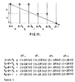
- ⁇ is no longer adequate on its own and a separate variable, ⁇ , is used which again varies linearly from 0 to 1 over the whole sequence.
- ⁇ is a measure of the timing of the output field, T, with respect to its position in the 5 field sequence.
- the total motion is 2V, since two frame periods have elapsed and so the motion gradient is (2/ ⁇ )V per field.
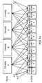
- Each field of the output video signal has contributions from four input fields as shown in figure 15. Accordingly, since the motion estimator can detect the phase of the 3:2 conversion the correct input fields contribute to each output field.
- An additional advantage of the ability of the motion estimator to calculate the phase of the 3:2 ratio conversion is that it is possible to convert the image even when part of the image sequence was stored on film or directly as a video electronic signal.
- An even greater advantage of being able to detect the phase of the 3:2 ratio conversion is to accommodate for when the ratio conversion is not continuous as which often happens after editing. This is because the motion estimator always measures the relative displacement and the address generator and interpolator compensate accordingly.
- the present invention is mainly applied to the conversion of images from film to video and between video standards, the present invention can also be used for the inverse operation of transferring video to film.
- the interlaced video signal is effectively converted to a sequential scan before conversion to film.
- the motion compensation is of great benefit to interlace to sequential conversion in general.
- the present invention is also applicable to converting from the PAL standard to the NTSC standard when part or all of the original image comes from film.
- the vector motion estimator 10 may be incorporated in the telecine 2 and used solely for converting from film to one of the TV standards.
- the vector motion estimator 10 may be incorporated in the standards converter 8. Otherwise, given the compatibility of the standards converter 8, the vector motion estimator 10 may be separate therefrom.
Landscapes
- Engineering & Computer Science (AREA)
- Multimedia (AREA)
- Signal Processing (AREA)
- Television Systems (AREA)
Applications Claiming Priority (4)
| Application Number | Priority Date | Filing Date | Title |
|---|---|---|---|
| GB9107980 | 1991-04-15 | ||
| GB919107980A GB9107980D0 (en) | 1991-04-15 | 1991-04-15 | An apparatus for method of transferring moving images from film to television |
| GB929204949A GB9204949D0 (en) | 1991-04-15 | 1992-03-06 | An apparatus for and method of transferring moving images from film to television |
| GB9204949 | 1992-03-06 |
Publications (2)
| Publication Number | Publication Date |
|---|---|
| EP0514012A2 true EP0514012A2 (de) | 1992-11-19 |
| EP0514012A3 EP0514012A3 (en) | 1993-11-18 |
Family
ID=26298730
Family Applications (1)
| Application Number | Title | Priority Date | Filing Date |
|---|---|---|---|
| EP19920303406 Withdrawn EP0514012A3 (en) | 1991-04-15 | 1992-04-15 | Method and apparatus for the standard conversion of an image signal |
Country Status (2)
| Country | Link |
|---|---|
| US (1) | US5428399A (de) |
| EP (1) | EP0514012A3 (de) |
Cited By (23)
| Publication number | Priority date | Publication date | Assignee | Title |
|---|---|---|---|---|
| WO1994001970A1 (en) * | 1992-07-03 | 1994-01-20 | Snell & Wilcox | Motion compensated video processing |
| EP0561561A3 (de) * | 1992-03-18 | 1994-01-26 | Sony Uk Ltd | |
| EP0576080A3 (en) * | 1992-06-26 | 1994-06-22 | Koninkl Philips Electronics Nv | Picture signal processing mode control |
| GB2277001A (en) * | 1993-04-08 | 1994-10-12 | Sony Uk Ltd | Motion compensated video standards conversion; simultaneous spatial and temporal interpolation. |
| WO1994030006A1 (en) * | 1993-06-08 | 1994-12-22 | Faroudja Y C | TELEVISION SIGNAL PROCESSING APPARATUS INCORPORATING MEANS FOR DETECTING 25 FRAME/SECOND MOTION PICTURE FILM SOURCES IN 50 Hz TELEVISION SIGNALS |
| EP0612187A3 (de) * | 1993-02-19 | 1996-06-05 | Philips Electronics Uk Ltd | Filmbilderkennung in einer Videosequenz. |
| US5537157A (en) * | 1993-04-21 | 1996-07-16 | Kinya Washino | Multi-format audio/video production system |
| WO1996027981A3 (en) * | 1995-03-03 | 1996-10-31 | Philips Electronics Nv | Video image processing |
| WO1998011721A1 (en) * | 1996-09-11 | 1998-03-19 | Philips Electronics N.V. | Adaptive picture delay |
| US5999220A (en) * | 1997-04-07 | 1999-12-07 | Washino; Kinya | Multi-format audio/video production system with frame-rate conversion |
| WO2001078406A1 (en) * | 2000-04-07 | 2001-10-18 | Snell & Wilcox Limited | Video signal processing |
| WO2002047382A3 (en) * | 2000-12-06 | 2002-09-12 | Koninkl Philips Electronics Nv | High quality, cost-effective film-to-video converter for high definition television |
| USRE38079E1 (en) * | 1993-04-21 | 2003-04-15 | Muti-Format, Inc. | Multi-format audio/video production system |
| WO2003055212A1 (fr) * | 2001-12-13 | 2003-07-03 | Sony Corporation | Appareil de traitement de signal d'image et procede de traitement |
| WO2003055211A1 (en) * | 2001-12-13 | 2003-07-03 | Sony Corporation | Image signal processing apparatus and processing method |
| WO2003056819A1 (fr) * | 2001-12-13 | 2003-07-10 | Sony Corporation | Appareil de traitement de signal d'image et procede de traitement |
| EP1592247A1 (de) * | 2004-04-30 | 2005-11-02 | Matsushita Electric Industrial Co., Ltd. | Blocktyp adaptive Bewegungskompensation |
| WO2008136116A1 (ja) * | 2007-04-26 | 2008-11-13 | Pioneer Corporation | 内挿フレーム作成制御装置、フレームレート変換装置、表示装置、内挿フレーム作成制御方法、そのプログラム、および、そのプログラムを記録した記録媒体 |
| US7474696B2 (en) | 1997-04-07 | 2009-01-06 | Multi-Format, Inc. | Wide-band multi-format audio/video production system with frame-rate conversion |
| USRE42020E1 (en) | 1993-04-21 | 2011-01-04 | Multi-Format, Inc. | Dual compression format digital video production system |
| EP2320649A4 (de) * | 2008-07-18 | 2011-07-27 | Victor Company Of Japan | Videosignalprozessor und videosignalverarbeitungsverfahren |
| CN101883225B (zh) * | 2009-05-06 | 2012-06-27 | 晨星软件研发(深圳)有限公司 | 用以消除影像误差的滤波器与方法 |
| WO2013007822A1 (en) * | 2011-07-13 | 2013-01-17 | Trident Microsystems, Inc. | Method and apparatus for motion estimation in video image data |
Families Citing this family (34)
| Publication number | Priority date | Publication date | Assignee | Title |
|---|---|---|---|---|
| CA2139420C (en) * | 1992-07-01 | 2000-12-12 | Eric C. Peters | Electronic film editing system using both film and videotape format |
| JP3151079B2 (ja) * | 1993-04-05 | 2001-04-03 | 日本電信電話株式会社 | アニメーションのエイリアシング除去方法 |
| DE69510851T2 (de) * | 1994-03-30 | 1999-12-02 | Thomson Multimedia, Boulogne | Verfahren und Gerät zur Reduzierung von Umwandlungsartefakten |
| JP2947400B2 (ja) * | 1994-05-31 | 1999-09-13 | 日本ビクター株式会社 | フレーム周波数変換装置 |
| JP3604732B2 (ja) * | 1994-07-01 | 2004-12-22 | キヤノン株式会社 | 映像システム |
| US5929902A (en) * | 1996-02-28 | 1999-07-27 | C-Cube Microsystems | Method and apparatus for inverse telecine processing by fitting 3:2 pull-down patterns |
| JPH09307857A (ja) * | 1996-05-17 | 1997-11-28 | Sony Corp | 画像信号処理装置及び画像信号処理方法 |
| US6462785B1 (en) * | 1997-06-04 | 2002-10-08 | Lucent Technologies Inc. | Motion display technique |
| US6108041A (en) * | 1997-10-10 | 2000-08-22 | Faroudja Laboratories, Inc. | High-definition television signal processing for transmitting and receiving a television signal in a manner compatible with the present system |
| US6014182A (en) * | 1997-10-10 | 2000-01-11 | Faroudja Laboratories, Inc. | Film source video detection |
| JP2000165821A (ja) * | 1998-11-30 | 2000-06-16 | Fujitsu Ltd | 画像フォーマット変換装置及び画像フォーマット変換方法 |
| US6542198B1 (en) * | 1999-03-30 | 2003-04-01 | Ati International Srl | Method and apparatus for optimizing video playback at arbitrary refresh rates |
| EP1340382A1 (de) * | 2000-11-22 | 2003-09-03 | Koninklijke Philips Electronics N.V. | Dekomprimierung komprimierte kodierter videodaten |
| US7020197B2 (en) * | 2001-08-24 | 2006-03-28 | Sanyo Electric Co., Ltd. | Telecine converting method |
| JP2003299038A (ja) * | 2002-04-05 | 2003-10-17 | Sony Corp | フレーム変換装置及びフレーム変換方法 |
| US7009655B2 (en) * | 2002-07-23 | 2006-03-07 | Mediostream, Inc. | Method and system for direct recording of video information onto a disk medium |
| US6828973B2 (en) * | 2002-08-02 | 2004-12-07 | Nexvisions Llc | Method and system for 3-D object modeling |
| US20040090554A1 (en) * | 2002-10-23 | 2004-05-13 | Takahiro Nishi | Picture coding method |
| JP3729189B2 (ja) * | 2003-07-18 | 2005-12-21 | ソニー株式会社 | 撮像装置 |
| JP4382408B2 (ja) * | 2003-07-31 | 2009-12-16 | パイオニア株式会社 | 映像信号変換装置 |
| US20070014359A1 (en) * | 2003-10-09 | 2007-01-18 | Cristina Gomila | Direct mode derivation process for error concealment |
| US8861589B2 (en) * | 2004-01-30 | 2014-10-14 | Broadcom Corporation | Detection and phase lock of pull-down video |
| US7557861B2 (en) * | 2004-01-30 | 2009-07-07 | Broadcom Corporation | Reverse pull-down video using corrective techniques |
| US7809155B2 (en) * | 2004-06-30 | 2010-10-05 | Intel Corporation | Computing a higher resolution image from multiple lower resolution images using model-base, robust Bayesian estimation |
| US7468756B2 (en) * | 2004-10-05 | 2008-12-23 | Broadcom Corporation | Detection and phase lock of 2:2 and 3:2 pull-down video |
| US7468757B2 (en) * | 2004-10-05 | 2008-12-23 | Broadcom Corporation | Detection and correction of irregularities while performing inverse telecine deinterlacing of video |
| KR100594780B1 (ko) * | 2004-10-09 | 2006-06-30 | 삼성전자주식회사 | 영상변환 장치 및 그 방법 |
| KR100732683B1 (ko) * | 2005-05-06 | 2007-06-27 | 삼성전자주식회사 | 움직임 보상을 수행하는 영상변환장치 및 움직임 보상방법 |
| JP4346591B2 (ja) * | 2005-08-25 | 2009-10-21 | 株式会社東芝 | 映像処理装置、映像処理方法およびプログラム |
| JP5059862B2 (ja) * | 2006-08-21 | 2012-10-31 | トライデント マイクロシステムズ インコーポレイテッド | 映像信号の動き補償処理の方法および装置 |
| US7822293B2 (en) * | 2006-11-17 | 2010-10-26 | Aptina Imaging Corporation | Imaging systems and method for generating video data using edge-aware interpolation with soft-thresholding |
| US8736759B2 (en) * | 2008-08-05 | 2014-05-27 | Mediatek Inc. | Methods and related apparatus making effective use of bandwidth of storage device to generate interpolated frames |
| US8457206B2 (en) | 2008-11-03 | 2013-06-04 | Broadcom Corporation | Method and system for adaptive temporal interpolation filtering for motion compensation |
| CN101931819B (zh) * | 2009-06-26 | 2012-12-26 | 宏碁股份有限公司 | 时间性错误隐藏方法 |
Family Cites Families (8)
| Publication number | Priority date | Publication date | Assignee | Title |
|---|---|---|---|---|
| DE3851718T2 (de) * | 1987-06-09 | 1995-01-26 | Sony Corp | Fernsehnormwandler. |
| EP0294957B1 (de) * | 1987-06-09 | 1995-04-12 | Sony Corporation | Verarbeitung des Bewegungsvektors in digitalen Fernsehbildern |
| EP0294958B1 (de) * | 1987-06-09 | 1995-08-23 | Sony Corporation | Bewegungskompensierte Interpolation von digitalen Fernsehbildern |
| GB2231228B (en) * | 1989-04-27 | 1993-09-22 | Sony Corp | Video signal to photographic film conversion |
| GB2231751B (en) * | 1989-04-27 | 1993-09-22 | Sony Corp | Motion dependent video signal processing |
| US4998167A (en) * | 1989-11-14 | 1991-03-05 | Jaqua Douglas A | High resolution translation of images |
| US5221966A (en) * | 1990-01-17 | 1993-06-22 | Avesco Plc | Video signal production from cinefilm originated material |
| GB9001079D0 (en) * | 1990-01-17 | 1990-03-14 | Avesco Plc | Standards conversion |
-
1992
- 1992-04-15 EP EP19920303406 patent/EP0514012A3/en not_active Withdrawn
- 1992-04-15 US US07/868,438 patent/US5428399A/en not_active Expired - Lifetime
Cited By (41)
| Publication number | Priority date | Publication date | Assignee | Title |
|---|---|---|---|---|
| US5355169A (en) * | 1992-03-18 | 1994-10-11 | Sony United Kingdom Limited | Method for processing a digital video signal having portions acquired with different acquisition characteristics |
| EP0561561A3 (de) * | 1992-03-18 | 1994-01-26 | Sony Uk Ltd | |
| EP0576080A3 (en) * | 1992-06-26 | 1994-06-22 | Koninkl Philips Electronics Nv | Picture signal processing mode control |
| US5784114A (en) * | 1992-07-03 | 1998-07-21 | Snell & Wilcox Ltd | Motion compensated video processing |
| AU668196B2 (en) * | 1992-07-03 | 1996-04-26 | Snell & Wilcox Limited | Motion compensated video processing |
| WO1994001970A1 (en) * | 1992-07-03 | 1994-01-20 | Snell & Wilcox | Motion compensated video processing |
| CN1069480C (zh) * | 1993-02-19 | 2001-08-08 | 皇家菲利浦电子有限公司 | 电视录象系中影片画格的识别设备 |
| EP0612187A3 (de) * | 1993-02-19 | 1996-06-05 | Philips Electronics Uk Ltd | Filmbilderkennung in einer Videosequenz. |
| GB2277001A (en) * | 1993-04-08 | 1994-10-12 | Sony Uk Ltd | Motion compensated video standards conversion; simultaneous spatial and temporal interpolation. |
| GB2277001B (en) * | 1993-04-08 | 1997-09-24 | Sony Uk Ltd | Motion compensated video standards conversion |
| US5537157A (en) * | 1993-04-21 | 1996-07-16 | Kinya Washino | Multi-format audio/video production system |
| USRE42020E1 (en) | 1993-04-21 | 2011-01-04 | Multi-Format, Inc. | Dual compression format digital video production system |
| USRE38079E1 (en) * | 1993-04-21 | 2003-04-15 | Muti-Format, Inc. | Multi-format audio/video production system |
| WO1994030006A1 (en) * | 1993-06-08 | 1994-12-22 | Faroudja Y C | TELEVISION SIGNAL PROCESSING APPARATUS INCORPORATING MEANS FOR DETECTING 25 FRAME/SECOND MOTION PICTURE FILM SOURCES IN 50 Hz TELEVISION SIGNALS |
| WO1996027981A3 (en) * | 1995-03-03 | 1996-10-31 | Philips Electronics Nv | Video image processing |
| US5881205A (en) * | 1995-03-03 | 1999-03-09 | U.S. Philips Corporation | Video image processing to product recorded media |
| US6411341B1 (en) * | 1996-09-11 | 2002-06-25 | U.S. Philips Corporation | Adaptive picture delay |
| WO1998011721A1 (en) * | 1996-09-11 | 1998-03-19 | Philips Electronics N.V. | Adaptive picture delay |
| US5999220A (en) * | 1997-04-07 | 1999-12-07 | Washino; Kinya | Multi-format audio/video production system with frame-rate conversion |
| US7474696B2 (en) | 1997-04-07 | 2009-01-06 | Multi-Format, Inc. | Wide-band multi-format audio/video production system with frame-rate conversion |
| US8873640B2 (en) | 1997-04-07 | 2014-10-28 | Kinya Washino | Wide-band multi-format audio/video production system with frame rate conversion |
| US8842727B2 (en) | 1997-04-07 | 2014-09-23 | Kinya Washino | Wide-band multi-format audio/video production system with frame-rate conversion |
| US8228979B2 (en) | 1997-04-07 | 2012-07-24 | Multi-Format, Inc. | Wide-band multi-format audio/video production system with frame-rate conversion |
| WO2001078406A1 (en) * | 2000-04-07 | 2001-10-18 | Snell & Wilcox Limited | Video signal processing |
| US7202909B2 (en) * | 2000-04-07 | 2007-04-10 | Snell & Wilcox Limited | Video signal processing with two stage motion compensation |
| WO2002047382A3 (en) * | 2000-12-06 | 2002-09-12 | Koninkl Philips Electronics Nv | High quality, cost-effective film-to-video converter for high definition television |
| US6847406B2 (en) | 2000-12-06 | 2005-01-25 | Koninklijke Philips Electronics N.V. | High quality, cost-effective film-to-video converter for high definition television |
| WO2003055212A1 (fr) * | 2001-12-13 | 2003-07-03 | Sony Corporation | Appareil de traitement de signal d'image et procede de traitement |
| WO2003056819A1 (fr) * | 2001-12-13 | 2003-07-10 | Sony Corporation | Appareil de traitement de signal d'image et procede de traitement |
| US7327397B2 (en) | 2001-12-13 | 2008-02-05 | Sony Corporation | Image processing with pixel interpolation |
| CN100373939C (zh) * | 2001-12-13 | 2008-03-05 | 索尼株式会社 | 影像信号处理装置和方法 |
| CN1328907C (zh) * | 2001-12-13 | 2007-07-25 | 索尼株式会社 | 图像信号处理装置和方法 |
| WO2003055211A1 (en) * | 2001-12-13 | 2003-07-03 | Sony Corporation | Image signal processing apparatus and processing method |
| US7221403B2 (en) | 2001-12-13 | 2007-05-22 | Sony Corporation | Image signal processing apparatus and processing method |
| US7215377B2 (en) | 2001-12-13 | 2007-05-08 | Sony Corporation | Image signal processing apparatus and processing method |
| US7440032B2 (en) | 2004-04-30 | 2008-10-21 | Matsushita Electric Industrial Co., Ltd. | Block mode adaptive motion compensation |
| EP1592247A1 (de) * | 2004-04-30 | 2005-11-02 | Matsushita Electric Industrial Co., Ltd. | Blocktyp adaptive Bewegungskompensation |
| WO2008136116A1 (ja) * | 2007-04-26 | 2008-11-13 | Pioneer Corporation | 内挿フレーム作成制御装置、フレームレート変換装置、表示装置、内挿フレーム作成制御方法、そのプログラム、および、そのプログラムを記録した記録媒体 |
| EP2320649A4 (de) * | 2008-07-18 | 2011-07-27 | Victor Company Of Japan | Videosignalprozessor und videosignalverarbeitungsverfahren |
| CN101883225B (zh) * | 2009-05-06 | 2012-06-27 | 晨星软件研发(深圳)有限公司 | 用以消除影像误差的滤波器与方法 |
| WO2013007822A1 (en) * | 2011-07-13 | 2013-01-17 | Trident Microsystems, Inc. | Method and apparatus for motion estimation in video image data |
Also Published As
| Publication number | Publication date |
|---|---|
| US5428399A (en) | 1995-06-27 |
| EP0514012A3 (en) | 1993-11-18 |
Similar Documents
| Publication | Publication Date | Title |
|---|---|---|
| US5428399A (en) | Method and apparatus for image translation with improved motion compensation | |
| US4862267A (en) | Motion compensated interpolation of digital television images | |
| EP0393906B1 (de) | Interpolation eines Videosignals | |
| US4864398A (en) | Motion vector processing in digital television images | |
| US5221966A (en) | Video signal production from cinefilm originated material | |
| US4901145A (en) | Motion vector estimation in television images | |
| US5526053A (en) | Motion compensated video signal processing | |
| EP0294961A2 (de) | Auswahl eines Bewegungsvektors in Fernsehbildern | |
| US4862266A (en) | Television standards converters | |
| JPH04273678A (ja) | デジタルビデオ信号フォーマット変換方式 | |
| US4862260A (en) | Motion vector processing in television images | |
| KR0141702B1 (ko) | 움직임 백터 처리방법 및 그 장치 | |
| GB2240232A (en) | Converting field rate of telecine signal | |
| US5450506A (en) | Image data processing apparatus and method | |
| GB2205713A (en) | Motion compensated interpolation of digital television images | |
| JP3946780B2 (ja) | ビデオ信号同期装置 | |
| US5299073A (en) | Video tape recorder speed control | |
| US5495293A (en) | Frame synchronizer and a signal switching apparatus | |
| GB2277004A (en) | Motion compensated video signal processing; motion/no motion flag | |
| KR970010044B1 (ko) | 텔레비젼 영상 움직임 벡터 평가 방법 및 장치 | |
| EP0382151A2 (de) | Abtastfrequenzabwärtswandler und Abtastfrequenzaufwärtswandler | |
| Mason et al. | Applications of motion compensation to standards conversion and film transfer | |
| JPH10210498A (ja) | 画像データの編集装置 | |
| JPH06205374A (ja) | 画像補間回路 | |
| GB2230914A (en) | Video signal interpolation |
Legal Events
| Date | Code | Title | Description |
|---|---|---|---|
| PUAI | Public reference made under article 153(3) epc to a published international application that has entered the european phase |
Free format text: ORIGINAL CODE: 0009012 |
|
| AK | Designated contracting states |
Kind code of ref document: A2 Designated state(s): DE ES FR GB IT NL SE |
|
| PUAL | Search report despatched |
Free format text: ORIGINAL CODE: 0009013 |
|
| AK | Designated contracting states |
Kind code of ref document: A3 Designated state(s): DE ES FR GB IT NL SE |
|
| 17P | Request for examination filed |
Effective date: 19940512 |
|
| 17Q | First examination report despatched |
Effective date: 19960917 |
|
| STAA | Information on the status of an ep patent application or granted ep patent |
Free format text: STATUS: THE APPLICATION IS DEEMED TO BE WITHDRAWN |
|
| 18D | Application deemed to be withdrawn |
Effective date: 19980512 |