EP0514044A2 - Seilklemme - Google Patents
Seilklemme Download PDFInfo
- Publication number
- EP0514044A2 EP0514044A2 EP92303910A EP92303910A EP0514044A2 EP 0514044 A2 EP0514044 A2 EP 0514044A2 EP 92303910 A EP92303910 A EP 92303910A EP 92303910 A EP92303910 A EP 92303910A EP 0514044 A2 EP0514044 A2 EP 0514044A2
- Authority
- EP
- European Patent Office
- Prior art keywords
- locking means
- cylindrical tube
- pair
- cord retainer
- retainer
- Prior art date
- Legal status (The legal status is an assumption and is not a legal conclusion. Google has not performed a legal analysis and makes no representation as to the accuracy of the status listed.)
- Granted
Links
Images

Classifications
-
- F—MECHANICAL ENGINEERING; LIGHTING; HEATING; WEAPONS; BLASTING
- F16—ENGINEERING ELEMENTS AND UNITS; GENERAL MEASURES FOR PRODUCING AND MAINTAINING EFFECTIVE FUNCTIONING OF MACHINES OR INSTALLATIONS; THERMAL INSULATION IN GENERAL
- F16G—BELTS, CABLES, OR ROPES, PREDOMINANTLY USED FOR DRIVING PURPOSES; CHAINS; FITTINGS PREDOMINANTLY USED THEREFOR
- F16G11/00—Means for fastening cables or ropes to one another or to other objects; Caps or sleeves for fixing on cables or ropes
- F16G11/10—Quick-acting fastenings; Clamps holding in one direction only
- F16G11/101—Quick-acting fastenings; Clamps holding in one direction only deforming the cable by moving a part of the fastener
-
- A—HUMAN NECESSITIES
- A44—HABERDASHERY; JEWELLERY
- A44B—BUTTONS, PINS, BUCKLES, SLIDE FASTENERS, OR THE LIKE
- A44B99/00—Subject matter not provided for in other groups of this subclass
-
- Y—GENERAL TAGGING OF NEW TECHNOLOGICAL DEVELOPMENTS; GENERAL TAGGING OF CROSS-SECTIONAL TECHNOLOGIES SPANNING OVER SEVERAL SECTIONS OF THE IPC; TECHNICAL SUBJECTS COVERED BY FORMER USPC CROSS-REFERENCE ART COLLECTIONS [XRACs] AND DIGESTS
- Y10—TECHNICAL SUBJECTS COVERED BY FORMER USPC
- Y10T—TECHNICAL SUBJECTS COVERED BY FORMER US CLASSIFICATION
- Y10T24/00—Buckles, buttons, clasps, etc.
- Y10T24/39—Cord and rope holders
- Y10T24/3969—Sliding part or wedge
-
- Y—GENERAL TAGGING OF NEW TECHNOLOGICAL DEVELOPMENTS; GENERAL TAGGING OF CROSS-SECTIONAL TECHNOLOGIES SPANNING OVER SEVERAL SECTIONS OF THE IPC; TECHNICAL SUBJECTS COVERED BY FORMER USPC CROSS-REFERENCE ART COLLECTIONS [XRACs] AND DIGESTS
- Y10—TECHNICAL SUBJECTS COVERED BY FORMER USPC
- Y10T—TECHNICAL SUBJECTS COVERED BY FORMER US CLASSIFICATION
- Y10T24/00—Buckles, buttons, clasps, etc.
- Y10T24/39—Cord and rope holders
- Y10T24/3984—Alignable aperture and spring pressed moving element
-
- Y—GENERAL TAGGING OF NEW TECHNOLOGICAL DEVELOPMENTS; GENERAL TAGGING OF CROSS-SECTIONAL TECHNOLOGIES SPANNING OVER SEVERAL SECTIONS OF THE IPC; TECHNICAL SUBJECTS COVERED BY FORMER USPC CROSS-REFERENCE ART COLLECTIONS [XRACs] AND DIGESTS
- Y10—TECHNICAL SUBJECTS COVERED BY FORMER USPC
- Y10T—TECHNICAL SUBJECTS COVERED BY FORMER US CLASSIFICATION
- Y10T403/00—Joints and connections
- Y10T403/57—Distinct end coupler
- Y10T403/5733—Plural opposed sockets
Definitions
- This invention relates to a retainer assembly for retaining in position cords or strings that fasten jackets, sports wear, hoods, shoes and the like.
- a typical prior example comprises a tubular body having registering holes adjacent to opposite ends, a pair of end taps having corresponding holes and adapted to fixedly close the respective ends of the body and a compression spring interposed therebetween, the arrangement being that the taps are brought toward each other axially of the tubular body against the tension of the compression spring until the holes in the tubular body register with the holes in the end taps.
- This type of retainer is disclosed for example in Japanese Laid-Open Utility Model Publications Nos. 57-203809, 63-524l2 and 63-ll7308. The retainer is split into halves, one of which is assembled with the compression spring and one end tap and thereafter joined with the other half portion.
- engaging means provided in the inner surface of the tubular body and in the outer surface of the respective taps are joined together by rotating the taps relative to the tubular body. This assembling procedure is literally tedious and time-consuming.
- FIG. 2-28609 Another prior art device is shown in Japanese Laid-Open Utility Model Publication No. 2-28609 in which there is provided a cord retainer having a tubular body with a centrally located hole, an outer sleeve fixedly connected to one end of the tubular body and an inner sleeve movable within the outer sleeve, the two sleeves having respective holes registrable with the central hole in the tubular body against the tension of a compression coil spring interposed between the sleeves. Assembly of this cord retainer is likewise complex, involving increased numbers of component parts and hence higher cost.
- the present invention seeks to provide a cord retainer which is relatively simple in construction with the number of component parts reduced to an absolute minimum and highly reliable in operation.
- a cord retainer comprises a cylindrical tube forming a retainer body, a pair of end taps adapted to close opposite ends of the tube, and a resilient locking means disposed centrally in the tube and resiliently engageable with the end taps to allow the latter to make an axial movement relative to the tube, all of the component parts of the retainer being preferably made from a plastics material for ease of manufacture and for the purposes which are hereinafter described.
- a cord retainer which comprises: a cylindrical tube having a pair of diammetrically aligned holes at each of its opposite ends; a resilient locking means fixedly mounted in the cylindrical tube and having upper and lower wing members interconnected centrally in spaced-apart relation to provide a pair of identical chambers, the wing members each having inwardly directed end flanges and each being bent arcuately inwardly with the end flanges held in closely confronting relation to define a slit (19) at each end of said locking means; and a pair of end taps each having through bores registrable with the holes of the cylindrical tube and each having an arrow-headed portion for anchoring engagement with the locking means.
- the retainer l0 for retaining cords, strings or the like against unintentional displacement relative to an article to which they are attached.
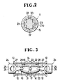
- the retainer l0 herein comprehensively referred to as a cord retainer, comprises a cylindrical tube ll forming a retainer body which is provided with a pair of elongate or otherwise round holes 11, 12 registering with each other diammetrically across the tube ll adjacent to one end thereof, and a similar pair of aligned holes l2, l2 adjacent to the opposite end of the tube ll for receiving a cord C ( Figure 5) or the like.
- the cylindrical tube ll has annular flanges l3, l3 at the respective ends and a plurality (three in the illustrated embodiment) of annular rims l4 spaced around its central periphery for purposes later described.
- a resilient locking means which comprises a pair of upper and lower wing members l6, l6 interconnected centrally in spaced-apart relation by a connecting post l7 which provides on opposite sides thereof two identical chambers l8, l8 and which extends substantially diammetrically across the interior of tube ll when the retainer l0 is assembled as shown in Figure 3.
- the upper and lower wing members l6, l6 are bent arcuately inwardly about the connecting post l7 with their respective inwardly directed end flanges l6a, l6a held in closely confronting relation to define therebetween a small gap or slit l9 communicating with corresponding chamber l8 at each of their opposite ends.
- An arcuate rib 20 is formed on the outer surface of each of the upper and lower wing members l6, l6 and extends centrally longitudinally thereof as better shown in Figure l.
- the connecting post l7 has a pair of lugs 2l, 2l projecting laterally from opposite ends thereof and each having a recess 2la.
- the resilient locking means l5 thus constructed is assembled into the cylindrical tube ll, in which instance the arcuate ribs 20, 20 are inserted in diammetrically opposed engaging grooves 22, 22 formed axially in the inner wall of the tube ll, and the recesses 2la, 2la of the lugs 2l, 2l are held in receptive engagement with diammetrically opposed pins 23, 23 projecting inwardly from the inner wall of the tube ll at an angular distance of substantially 90° apart from the engaging grooves 22, 22 as better shown in Figure 2.
- lugs 2l, 2l with recesses 2la, 2la for engagement with the pins 23, 23 can be disposed with, if arrangements are made such that the arcuate ribs 20, 20 are clamped under pressure into firm gripping engagement with the engaging grooves 22, 22.
- Each end tap 24 has a barrel portion 25 substantially round in cross section and slightly smaller in diameter than the inside diameter of the cylindrical tube ll so that the end tap 24 can move within and through the tube ll in a manner later described.
- the tap 24 has a through bore 26 extending diammetrically across the barrel portion 25 and registrable with the holes l2, l2 of the cylindrical tube ll.
- the tap 24 includes a tapered connecting portion 27 with opposite surfaces 27a, 27a thereof progressively converging from the barrel portion 25 toward a cross-sectionally arrow-headed anchoring portion 28 disposed remotely from the barrel portion 25.
- the anchoring portion 28 has vertical abutments 29 bordering with a reduced terminal end 27b of the tapered connecting portion 27 opposite to a thicker end 27c thereof merging with the barrel portion 25.
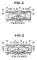
- the resilient locking means l5 When assembling the cord retainer l0, the resilient locking means l5 is inserted into and fixed in place within the cylindrical tube ll in the manner above described, followed by mounting the pair of end taps 24, 24 from opposite ends of the tube ll, in which instance the barrel portion 25 of each tap is pushed axially inward through the tubular body ll of the retainer l0 until the arrow-headed anchoring portion 28 passes through the slit l9 of the locking means l5 into the chamber l8, urging the slit l9 to spread open against the tension between the upper and lower wing members l6, l6.
- each tap 24 to retract outwardly under the influence of tension exerted by the wing members l6, l6 with the arrow-headed portion 28 snapped in place (with its vertical abutments 29 borne against the inner walls of the end flanges l6a, l6a of the wing members l6, l6), as shown in Figure 3.
- the end taps 24, 24 are released so that the taps 24, 24 are urged to retract or move outwardly away from each other by the tension or closing force of the locking means l5, whereupon the through bores 26, 26 in the respective end taps 24, 24 become displaced with respect to their associated holes l2, l2 in the cylindrical tube ll, leaving the cord C immovably trapped in the retainer l0 as shown in Figure 5.
Landscapes
- Engineering & Computer Science (AREA)
- General Engineering & Computer Science (AREA)
- Mechanical Engineering (AREA)
- Supports For Pipes And Cables (AREA)
- Buckles (AREA)
- Flexible Shafts (AREA)
- Clamps And Clips (AREA)
Applications Claiming Priority (2)
| Application Number | Priority Date | Filing Date | Title |
|---|---|---|---|
| JP1991040142U JP2561565Y2 (ja) | 1991-05-01 | 1991-05-01 | コードストッパー |
| JP40142/91 | 1991-05-01 |
Publications (3)
| Publication Number | Publication Date |
|---|---|
| EP0514044A2 true EP0514044A2 (de) | 1992-11-19 |
| EP0514044A3 EP0514044A3 (de) | 1992-11-25 |
| EP0514044B1 EP0514044B1 (de) | 1995-12-27 |
Family
ID=12572529
Family Applications (1)
| Application Number | Title | Priority Date | Filing Date |
|---|---|---|---|
| EP92303910A Expired - Lifetime EP0514044B1 (de) | 1991-05-01 | 1992-04-30 | Seilklemme |
Country Status (5)
| Country | Link |
|---|---|
| US (1) | US5224245A (de) |
| EP (1) | EP0514044B1 (de) |
| JP (1) | JP2561565Y2 (de) |
| KR (1) | KR940001555Y1 (de) |
| DE (1) | DE69207064T2 (de) |
Cited By (3)
| Publication number | Priority date | Publication date | Assignee | Title |
|---|---|---|---|---|
| EP0537974A1 (de) * | 1991-10-17 | 1993-04-21 | Ykk Corporation | Seilklemme |
| EP0570814B1 (de) * | 1992-05-20 | 1996-05-29 | Ykk Corporation | Seilklemme |
| RU2249737C2 (ru) * | 2003-03-24 | 2005-04-10 | Марийский государственный технический университет | Устройство для соединения канатов |
Families Citing this family (17)
| Publication number | Priority date | Publication date | Assignee | Title |
|---|---|---|---|---|
| US5711032A (en) * | 1994-08-09 | 1998-01-27 | Carpenter; Jake | Locking apparatus for a draw cord |
| JP3254095B2 (ja) * | 1995-02-28 | 2002-02-04 | ワイケイケイ株式会社 | 紐固定具 |
| US5967151A (en) * | 1996-01-18 | 1999-10-19 | Beadwear, Inc. | Hair bead stop and method of beading hair |
| US5924178A (en) * | 1998-04-17 | 1999-07-20 | Lazylock Ab | Tightening device for shoelaces and like elongated and pliable elements having free ends |
| IT243966Y1 (it) * | 1998-04-27 | 2002-03-06 | System Plast Snc Marsetti & C | Organo di serraggio per almeno un perno di supporto di componentidi trasportatori a nastro |
| US5961062A (en) * | 1998-05-21 | 1999-10-05 | Beihl; Amanda Herbst | Retaining cords |
| US6016813A (en) * | 1998-09-04 | 2000-01-25 | Beadwear, Inc. | Bead lock and method of retaining beads |
| USD536173S1 (en) | 1999-06-04 | 2007-02-06 | Snugz Usa, Inc. | Lanyard connector surface |
| USD539697S1 (en) | 1999-06-04 | 2007-04-03 | Snugz Usa, Inc. | Lanyard connector |
| USD507110S1 (en) | 1999-06-04 | 2005-07-12 | Bryan K. Hicks | Lanyard connector |
| US6711785B1 (en) * | 1999-06-04 | 2004-03-30 | Bryan K. Hicks | Lanyard connector and system |
| US20090025616A1 (en) * | 2007-07-23 | 2009-01-29 | Amsafe, Inc. | Air cargo pallets having synthetic cores and associated systems and methods for manufacturing same |
| US20100031477A1 (en) * | 2008-08-05 | 2010-02-11 | Charles Lamar Harrison | Adjustable retainer |
| TW201100031A (en) * | 2009-06-16 | 2011-01-01 | kun-zhong Liu | Shoelace length adjustment device |
| JP5687850B2 (ja) * | 2010-06-02 | 2015-03-25 | 株式会社ニフコ | コードロック |
| USD682909S1 (en) * | 2012-01-31 | 2013-05-21 | Samsung Electronics Co., Ltd. | Straps connector |
| USD751400S1 (en) * | 2014-04-25 | 2016-03-15 | Designetics, Inc. | Receptacle for inverted containers |
Family Cites Families (15)
| Publication number | Priority date | Publication date | Assignee | Title |
|---|---|---|---|---|
| GB549947A (en) * | 1941-11-14 | 1942-12-15 | Fullerton George Gordon Armstr | Improvements in or relating to rapid releasable couplings |
| US3080867A (en) * | 1958-05-22 | 1963-03-12 | Eichinger Maximilian | Clamping device |
| JPS55101205A (en) * | 1979-01-30 | 1980-08-01 | Yoshihiko Ishiguro | String camping tool |
| GB2066891B (en) * | 1980-01-03 | 1983-07-27 | Oppenheim M J | Cord securing device |
| US4393550A (en) * | 1981-04-20 | 1983-07-19 | James Yang | Safety clasp for the string of footwear |
| JPS57203809A (en) * | 1981-06-09 | 1982-12-14 | Yamaha Motor Co Ltd | Pressure reducing device at starting of engine with cranking starter |
| SE443909B (sv) * | 1982-12-16 | 1986-03-17 | Fixfabriken Ab | Snorlas |
| US4506417A (en) * | 1983-05-06 | 1985-03-26 | Nifco Inc. | Fastener for string |
| US4622723A (en) * | 1985-03-18 | 1986-11-18 | American Cord & Webbing Co., Inc. | Cord lock |
| JPS6352412A (ja) * | 1986-08-22 | 1988-03-05 | Hitachi Ltd | 薄膜のエツチング方法 |
| JPH053052Y2 (de) * | 1986-09-26 | 1993-01-26 | ||
| JP2618380B2 (ja) * | 1986-11-06 | 1997-06-11 | キヤノン電子 株式会社 | 磁気抵抗効果型磁気ヘツド及びその製造方法 |
| JPH053053Y2 (de) * | 1987-01-23 | 1993-01-26 | ||
| JPH0540731Y2 (de) * | 1987-05-01 | 1993-10-15 | ||
| JPH0228609U (de) * | 1988-08-18 | 1990-02-23 |
-
1991
- 1991-05-01 JP JP1991040142U patent/JP2561565Y2/ja not_active Expired - Fee Related
-
1992
- 1992-04-30 KR KR9207319U patent/KR940001555Y1/ko not_active Expired - Fee Related
- 1992-04-30 DE DE69207064T patent/DE69207064T2/de not_active Expired - Fee Related
- 1992-04-30 EP EP92303910A patent/EP0514044B1/de not_active Expired - Lifetime
- 1992-05-01 US US07/877,227 patent/US5224245A/en not_active Expired - Fee Related
Cited By (4)
| Publication number | Priority date | Publication date | Assignee | Title |
|---|---|---|---|---|
| EP0537974A1 (de) * | 1991-10-17 | 1993-04-21 | Ykk Corporation | Seilklemme |
| US5263232A (en) * | 1991-10-17 | 1993-11-23 | Yoshida Kogyo K.K. | Cord stopper |
| EP0570814B1 (de) * | 1992-05-20 | 1996-05-29 | Ykk Corporation | Seilklemme |
| RU2249737C2 (ru) * | 2003-03-24 | 2005-04-10 | Марийский государственный технический университет | Устройство для соединения канатов |
Also Published As
| Publication number | Publication date |
|---|---|
| EP0514044B1 (de) | 1995-12-27 |
| JPH04125709U (ja) | 1992-11-17 |
| DE69207064T2 (de) | 1996-08-22 |
| JP2561565Y2 (ja) | 1998-01-28 |
| KR940001555Y1 (ko) | 1994-03-19 |
| KR920020703U (ko) | 1992-12-18 |
| DE69207064D1 (de) | 1996-02-08 |
| EP0514044A3 (de) | 1992-11-25 |
| US5224245A (en) | 1993-07-06 |
Similar Documents
| Publication | Publication Date | Title |
|---|---|---|
| EP0514044A2 (de) | Seilklemme | |
| US3633250A (en) | Mechanical connector system including bifurcate hinged connector means | |
| CN1795346B (zh) | 瞬间偶联装置 | |
| US4635974A (en) | Rapidly assembled and disassembled connecting device | |
| US4272871A (en) | Hose coupling | |
| US7195286B2 (en) | Tube joint | |
| US4113397A (en) | Pinless resilient coupling | |
| US3329455A (en) | Clamp structure | |
| JPS62500734A (ja) | ケ−ブルなどの端部を迅速に固定する装置 | |
| KR102068303B1 (ko) | 철근 커플러 | |
| US3205759A (en) | Two-piece molding fastener | |
| EP0537974B1 (de) | Seilklemme | |
| RU2313718C2 (ru) | Разъемное соединение для высоконапорных трубопроводов | |
| US3455142A (en) | Tube bending mandrel | |
| US3378891A (en) | Cable enlargement clasp | |
| CN114174709A (zh) | 紧凑且可拆卸的流体连接装置 | |
| US2815227A (en) | Prepositioned coupling for swaged connections | |
| CN1197508A (zh) | 多导管管道的连接组件 | |
| US4083587A (en) | Split-ring type pipe couplings | |
| US2992845A (en) | Friction device | |
| US5615895A (en) | Seal arrangements | |
| US5820082A (en) | Holding element | |
| US946703A (en) | Hose-connector. | |
| US3514819A (en) | Releasable pins | |
| US6865793B2 (en) | Tubing splicer |
Legal Events
| Date | Code | Title | Description |
|---|---|---|---|
| PUAI | Public reference made under article 153(3) epc to a published international application that has entered the european phase |
Free format text: ORIGINAL CODE: 0009012 |
|
| PUAL | Search report despatched |
Free format text: ORIGINAL CODE: 0009013 |
|
| AK | Designated contracting states |
Kind code of ref document: A2 Designated state(s): DE FR GB IT |
|
| AK | Designated contracting states |
Kind code of ref document: A3 Designated state(s): DE FR GB IT |
|
| 17P | Request for examination filed |
Effective date: 19930212 |
|
| 17Q | First examination report despatched |
Effective date: 19940527 |
|
| RAP1 | Party data changed (applicant data changed or rights of an application transferred) |
Owner name: YKK CORPORATION |
|
| GRAA | (expected) grant |
Free format text: ORIGINAL CODE: 0009210 |
|
| AK | Designated contracting states |
Kind code of ref document: B1 Designated state(s): DE FR GB IT |
|
| ITF | It: translation for a ep patent filed | ||
| REF | Corresponds to: |
Ref document number: 69207064 Country of ref document: DE Date of ref document: 19960208 |
|
| PGFP | Annual fee paid to national office [announced via postgrant information from national office to epo] |
Ref country code: FR Payment date: 19960328 Year of fee payment: 5 |
|
| ET | Fr: translation filed | ||
| PGFP | Annual fee paid to national office [announced via postgrant information from national office to epo] |
Ref country code: GB Payment date: 19960422 Year of fee payment: 5 |
|
| PGFP | Annual fee paid to national office [announced via postgrant information from national office to epo] |
Ref country code: DE Payment date: 19960531 Year of fee payment: 5 |
|
| PLBE | No opposition filed within time limit |
Free format text: ORIGINAL CODE: 0009261 |
|
| STAA | Information on the status of an ep patent application or granted ep patent |
Free format text: STATUS: NO OPPOSITION FILED WITHIN TIME LIMIT |
|
| 26N | No opposition filed | ||
| PG25 | Lapsed in a contracting state [announced via postgrant information from national office to epo] |
Ref country code: GB Effective date: 19970430 |
|
| GBPC | Gb: european patent ceased through non-payment of renewal fee |
Effective date: 19970430 |
|
| PG25 | Lapsed in a contracting state [announced via postgrant information from national office to epo] |
Ref country code: FR Free format text: LAPSE BECAUSE OF NON-PAYMENT OF DUE FEES Effective date: 19971231 |
|
| PG25 | Lapsed in a contracting state [announced via postgrant information from national office to epo] |
Ref country code: DE Free format text: LAPSE BECAUSE OF NON-PAYMENT OF DUE FEES Effective date: 19980101 |
|
| REG | Reference to a national code |
Ref country code: FR Ref legal event code: ST |
|
| PG25 | Lapsed in a contracting state [announced via postgrant information from national office to epo] |
Ref country code: IT Free format text: LAPSE BECAUSE OF NON-PAYMENT OF DUE FEES;WARNING: LAPSES OF ITALIAN PATENTS WITH EFFECTIVE DATE BEFORE 2007 MAY HAVE OCCURRED AT ANY TIME BEFORE 2007. THE CORRECT EFFECTIVE DATE MAY BE DIFFERENT FROM THE ONE RECORDED. Effective date: 20050430 |