EP0514319A1 - Peigne circulaire pour une machine de peignage - Google Patents
Peigne circulaire pour une machine de peignage Download PDFInfo
- Publication number
- EP0514319A1 EP0514319A1 EP92810186A EP92810186A EP0514319A1 EP 0514319 A1 EP0514319 A1 EP 0514319A1 EP 92810186 A EP92810186 A EP 92810186A EP 92810186 A EP92810186 A EP 92810186A EP 0514319 A1 EP0514319 A1 EP 0514319A1
- Authority
- EP
- European Patent Office
- Prior art keywords
- segment
- roller body
- spacer elements
- round comb
- combing
- Prior art date
- Legal status (The legal status is an assumption and is not a legal conclusion. Google has not performed a legal analysis and makes no representation as to the accuracy of the status listed.)
- Withdrawn
Links
Images


Classifications
-
- D—TEXTILES; PAPER
- D01—NATURAL OR MAN-MADE THREADS OR FIBRES; SPINNING
- D01G—PRELIMINARY TREATMENT OF FIBRES, e.g. FOR SPINNING
- D01G19/00—Combing machines
- D01G19/06—Details
- D01G19/10—Construction, mounting, or operating features of combing elements
- D01G19/105—Combing cylinders
Definitions
- the invention relates to a round comb for a combing machine, with a roller body and a circular comb segment fastened to the roller body and equipped with combing needles or combing sets.
- Such round combs are used, for example, in combing machines with vibrating pliers.
- the pliers In a retracted, closed position, the pliers hold a fiber beard from a cotton wool to be combed, which is then combed out by the circular comb segment on the rotating roller body.
- the distance between the tips of the combing needles or combing sets and the clamping lips of the pliers should be as small as possible so that, for example, nits can be removed as completely as possible from the fiber beard.
- the tips of the combing needles or combing sets must not touch the pliers, as they would otherwise be damaged.
- a distance of about 0.3 to 0.5 mm, for example, is desirable.
- it is very difficult in practice to maintain such small distances precisely because small deviations in the dimensions of the parts of the circular comb, the pliers and the bearings are inevitable for the same from the target values.
- the object of the invention is to design the circular comb specified at the outset so that a desired small distance between the tips of the combing needles or combing sets and the clamping lips of a pliers of the combing machine (in the retracted position of the pliers) can be exactly maintained in a combing machine.
- the circular comb according to the invention is characterized in that the circular comb segment is held in a continuously adjustable radial distance from the roller body by means of adjustable spacer elements.
- the spacer elements can be held in the circular comb segment and be adjustable with respect to the same. This has the advantage that the application of the invention is possible in an existing, conventional circular comb without a substantial change in the roller body.
- the spacer elements can also be held in the roller body and be adjustable with respect to the same. With a suitable design, it is then possible to use an existing circular comb segment unchanged and only make changes to the roller body.
- the spacer elements can have external threads and can be screwed into threaded bores in the circular comb segment or in the roller body.
- other adjustable spacer elements for example wedges which are held displaceably in the roller body or pivotable cam disks, are also possible.
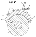
- the circular comb shown schematically in FIGS. 1 and 2 has a roller body 1 and a circular comb segment 2, the outer circumferential surface of which is occupied by combing needles or combing sets 3.
- the circular comb segment 2 is fastened on the roller body 1 in the usual way with four fastening screws 4 which are screwed into threaded holes in the roller body 1.
- a threaded hole is provided in the circular comb segment 2, which receives a set screw 5.
- the circular comb is used in a combing machine which contains a vibrating pliers. Of this, only the front part of a lower pliers plate 6 and the lower part of an upper pliers knife 7 are shown in FIG. 2.
- the circular comb segment 2 has a fiber beard (not shown) for combing out, which is clamped between the front edge of the lower pliers plate 6 and the lower edge of the upper pliers knife 7.
- a very small distance between the tips of the combing needles or combing sets 3 and the lower edge of the top-tongs knife 7 is desirable.
- the set screws 5 are closer to the ends of the roller body 1 than the fastening screws 4. This has the consequence that the radial forces exerted by the set screws 5 and by the fastening screws 4 on the circular comb segment 2 can bend the circular comb segment 2 slightly concave.
- Such a deflection of the circular comb segment 2, with which the distance between the tips of the combing needles or combing sets 3 and the lower edge of the upper-nose pliers 7 in the central region of the length of the roller body 1, for example, by approximately 0.1 mm (or 0.05 to 0 , 2 mm) larger than in the area of the ends of the roller body 1, is advantageous:
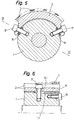
- FIG. 3 shows in a cross section through a circular comb two other embodiments of spacer elements which are adjustably held in the circular comb segment and which can be used instead of the set screws 5 from FIG. 2.
- a sleeve 8 is shown as a spacer element, which has an external thread which is screwed into a threaded bore in the circular comb segment 2.
- a screw 9 extends through the bore of the sleeve 8.
- the circular comb segment 2 is fastened on the roller body 1 with the screws 9.
- the sleeve 8 can be rotated in order to change the radial distance of the circular comb segment 2 from the roller body 1.
- the bore of the sleeve 8 can be designed as a hexagonal bore.
- a sleeve 10 serving as a spacer is shown, which, like the sleeve 8, has an external thread which is screwed into a threaded bore in the circular comb segment 2.
- a fastening screw 11 extends through the bore of the sleeve 10 and is screwed into a threaded bore in the roller body 1.
- the sleeve 10 extends out of the threaded hole in the circular comb segment 2, it can therefore be rotated without removing the screw 11, the screw 11 only has to be loosened somewhat.
- the sleeve 10 can have a collar 12 surrounding the head of the screw 11, which can be hexagonal on the outside for rotating the sleeve.
- the axis of the sleeve 10 and the screw 11 does not necessarily have to run radially to the roller body 1.
- the roller body 1 can have a flattened area for contacting the inner end of the sleeve 10. Due to the inclined arrangement of the axis of the sleeve 10 - approximately after a secant to the circumference of the roller body 1 - the game between the bore of the sleeve 10 and the circumference of the screw 11 can be somewhat smaller, which game is required due to the fact that the Rotating the sleeve 10 does not move the threaded bore in the circular comb segment 2 receiving it radially to the roller body 1, but rather approximately perpendicular to the connecting line with the opposite fastening point (where the screw 9 and the sleeve 8 are shown in FIG. 3).
- FIG. 4 shows, in a section similar to FIG. 2, two embodiments of spacer elements held adjustably in the roller body 1.
- a set screw 13 is shown as a spacer element, which has an external thread which is screwed into a threaded bore in the roller body 1.
- the set screw 13 which rests with its outer end on the inner surface of the circular comb segment 2, holds it at a continuously adjustable radial distance from the roller body 1.
- a fastening screw (not shown) similar to the screws 4 in FIGS. 1 and 2 arranged, which fastens the circular comb segment 2 on the roller body 1.
- a sleeve 14 is shown as a spacer element, which has an external thread which is screwed into a threaded bore in the roller body 1.
- a fastening screw 15 extends through the bore of the sleeve 14.
- the circular comb segment 2 is open with the screws 15 attached to the roller body 1.
- the spacer elements - adjusting screws 13 or sleeves 14 - measure the distances between the tips of the combing needles or combing sets 3 and the lower edge of the needle-nose knife 7 (FIG. 2) of the combing machine. Then the circular comb segment 2 is removed and the set screws 13 or sleeves 14 are turned so far that after the reattachment of the circular comb segment the distances mentioned have a desired predetermined size.
- these holes can contain hexagon socket (not shown).
- the bores in the sleeves 14 can be designed as hexagonal bores.
- a slight concave bending of the circular comb segment 2 can be advantageous.
- Such a bending can of course also be easily produced with set screws 13 according to FIG. 4 if these are closer to the ends of the roller body 1 than the fixing screws (not shown in FIG. 4).
- the sleeve-shaped spacer elements 8, 10 or 14 shown in FIGS. 3 and 4 which run coaxially with the fastening screws 9, 11 and 15, together with these do not cause any bending of the circular comb segment 2.
- the circular comb segment is bent To achieve 2, you can next to the sleeves 8, 10 or 14 with screws 9, 11 or 15, and closer to the ends of the roller body than this, additional set screws 5 (Fig. 1, 2) or set screws 13 (Fig. 4th ) arrange.
- Spacer elements which allow adjustment of the radial distance between circular comb segment 2 and roller body 1 without removing the circular comb segment - after simply loosening the fastening screws - could also be held adjustably in the roller body 1.
- spacer elements would be, for example, wedges that can be moved axially from the end faces of the roller body, or eccentrics or cam disks that can be turned from the end faces of the roller body.
- FIGS. 5 and 6 An embodiment with wedges 16 as spacer elements is shown schematically in FIGS. 5 and 6.
- the circular comb segment 2 is fastened here on the roller body 1 with fastening screws 17, which each extend through an elongated hole 16.1 in one of the wedges 16.
- Each wedge 16 is axially displaceable on an inclined wedge path 1.1 in the roller body 1 by turning an adjusting screw 18 which is screwed into a threaded bore in the end face of the roller body 1 and with its head at the end of the wedge 16 is present.
- the wedge 16 in turn lies with its top against the inner surface of the circular comb segment 2 and holds it at a continuously adjustable radial distance from the roller body 1.
Landscapes
- Engineering & Computer Science (AREA)
- Textile Engineering (AREA)
- Preliminary Treatment Of Fibers (AREA)
Applications Claiming Priority (2)
| Application Number | Priority Date | Filing Date | Title |
|---|---|---|---|
| CH140791A CH683190A5 (de) | 1991-05-10 | 1991-05-10 | Rundkamm für eine Kämmaschine. |
| CH1407/91 | 1991-05-10 |
Publications (1)
| Publication Number | Publication Date |
|---|---|
| EP0514319A1 true EP0514319A1 (fr) | 1992-11-19 |
Family
ID=4209725
Family Applications (1)
| Application Number | Title | Priority Date | Filing Date |
|---|---|---|---|
| EP92810186A Withdrawn EP0514319A1 (fr) | 1991-05-10 | 1992-03-13 | Peigne circulaire pour une machine de peignage |
Country Status (3)
| Country | Link |
|---|---|
| EP (1) | EP0514319A1 (fr) |
| JP (1) | JPH05125622A (fr) |
| CH (1) | CH683190A5 (fr) |
Cited By (6)
| Publication number | Priority date | Publication date | Assignee | Title |
|---|---|---|---|---|
| CN102965771A (zh) * | 2012-11-14 | 2013-03-13 | 经纬纺织机械股份有限公司 | 精梳机锡林紧固装置 |
| CN104711711A (zh) * | 2013-12-12 | 2015-06-17 | 株式会社丰田自动织机 | 用于精梳机的精梳锡林 |
| EP3467166A1 (fr) * | 2017-09-18 | 2019-04-10 | Trützschler GmbH & Co. KG | Cylindre de peignage rond pour une machine de peignage |
| EP3633085A1 (fr) | 2018-10-04 | 2020-04-08 | Graf + Cie AG | Peigne circulaire pour une peigneuse |
| EP3633084A1 (fr) * | 2018-10-04 | 2020-04-08 | Graf + Cie AG | Peigne circulaire pour une peigneuse |
| CN112095180A (zh) * | 2019-06-17 | 2020-12-18 | 格拉夫及西有限公司 | 用于精梳机的圆梳 |
Families Citing this family (4)
| Publication number | Priority date | Publication date | Assignee | Title |
|---|---|---|---|---|
| DE502004006649D1 (de) * | 2003-11-14 | 2008-05-08 | Rieter Ag Maschf | Rundkamm mit Garniturelementen |
| CH707882A2 (de) * | 2013-04-12 | 2014-10-15 | Rieter Ag Maschf | Rundkamm für eine Kämmmaschine. |
| EP3680371B1 (fr) | 2014-05-02 | 2023-02-22 | Staedtler + Uhl KG | Unités de peigne circulaire dotées d'un peigne circulaire fixé sur un arbre |
| DE102015221410A1 (de) | 2015-11-02 | 2017-05-04 | Staedtler + Uhl Kg | Kreiskamm mit Kämmriegeln und Grundkörper |
Citations (5)
| Publication number | Priority date | Publication date | Assignee | Title |
|---|---|---|---|---|
| DE62073C (de) * | L. OFFERMANN in Leipzig | heilmann'sche Kämm - Maschine | ||
| DE389608C (de) * | 1922-10-31 | 1924-02-08 | Hermann Heinrich | Kaemmtrommel fuer Kaemmaschinen |
| US2605512A (en) * | 1950-12-27 | 1952-08-05 | Terrell Mach Co | Comber half-lap |
| DE2613210A1 (de) * | 1976-03-27 | 1977-09-29 | Staedtler & Uhl | Nadelwalze mit nadelstreifen |
| CH620949A5 (en) * | 1976-06-04 | 1980-12-31 | Vyzk Ustav Bavlnarsky | Apparatus for opening fibres on open-end spinning-rotor units. |
-
1991
- 1991-05-10 CH CH140791A patent/CH683190A5/de not_active IP Right Cessation
-
1992
- 1992-03-13 EP EP92810186A patent/EP0514319A1/fr not_active Withdrawn
- 1992-05-08 JP JP11602692A patent/JPH05125622A/ja active Pending
Patent Citations (5)
| Publication number | Priority date | Publication date | Assignee | Title |
|---|---|---|---|---|
| DE62073C (de) * | L. OFFERMANN in Leipzig | heilmann'sche Kämm - Maschine | ||
| DE389608C (de) * | 1922-10-31 | 1924-02-08 | Hermann Heinrich | Kaemmtrommel fuer Kaemmaschinen |
| US2605512A (en) * | 1950-12-27 | 1952-08-05 | Terrell Mach Co | Comber half-lap |
| DE2613210A1 (de) * | 1976-03-27 | 1977-09-29 | Staedtler & Uhl | Nadelwalze mit nadelstreifen |
| CH620949A5 (en) * | 1976-06-04 | 1980-12-31 | Vyzk Ustav Bavlnarsky | Apparatus for opening fibres on open-end spinning-rotor units. |
Cited By (12)
| Publication number | Priority date | Publication date | Assignee | Title |
|---|---|---|---|---|
| CN102965771A (zh) * | 2012-11-14 | 2013-03-13 | 经纬纺织机械股份有限公司 | 精梳机锡林紧固装置 |
| CN104711711A (zh) * | 2013-12-12 | 2015-06-17 | 株式会社丰田自动织机 | 用于精梳机的精梳锡林 |
| CN104711711B (zh) * | 2013-12-12 | 2016-12-07 | 株式会社丰田自动织机 | 用于精梳机的精梳锡林 |
| EP3467166A1 (fr) * | 2017-09-18 | 2019-04-10 | Trützschler GmbH & Co. KG | Cylindre de peignage rond pour une machine de peignage |
| EP3633085A1 (fr) | 2018-10-04 | 2020-04-08 | Graf + Cie AG | Peigne circulaire pour une peigneuse |
| EP3633084A1 (fr) * | 2018-10-04 | 2020-04-08 | Graf + Cie AG | Peigne circulaire pour une peigneuse |
| CN111005097A (zh) * | 2018-10-04 | 2020-04-14 | 格拉夫及西有限公司 | 用于精梳机的圆梳 |
| CH715431A1 (de) * | 2018-10-04 | 2020-04-15 | Graf Cie Ag | Rundkamm für eine Klämmmaschine. |
| CN111005097B (zh) * | 2018-10-04 | 2023-05-23 | 格拉夫及西有限公司 | 用于精梳机的圆梳 |
| CN112095180A (zh) * | 2019-06-17 | 2020-12-18 | 格拉夫及西有限公司 | 用于精梳机的圆梳 |
| CH716329A1 (de) * | 2019-06-17 | 2020-12-30 | Graf Cie Ag | Rundkamm für eine Kämmmaschine. |
| CN112095180B (zh) * | 2019-06-17 | 2023-10-03 | 格拉夫及西有限公司 | 用于精梳机的圆梳 |
Also Published As
| Publication number | Publication date |
|---|---|
| CH683190A5 (de) | 1994-01-31 |
| JPH05125622A (ja) | 1993-05-21 |
Similar Documents
| Publication | Publication Date | Title |
|---|---|---|
| DE3922963C2 (de) | Drehräumwerkzeug | |
| EP0039765B1 (fr) | Dispositif pour le montage de plaques flexibles sur un cylindre de plaques pour rotatives | |
| EP0431482B1 (fr) | Enveloppe segmentaire de tambour | |
| EP0514319A1 (fr) | Peigne circulaire pour une machine de peignage | |
| EP0357549B1 (fr) | Couteaux rotatifs | |
| DE3505913C2 (fr) | ||
| DE2543661A1 (de) | Vorrichtung zum befestigen eines werkzeugs in einer maschinenspindel | |
| DE1640341B1 (de) | Elektrisches nockenschaltwerk | |
| DE2528485A1 (de) | Aufloesewalze | |
| DE2931167C2 (de) | Vorrichtung zum kompressiven Schrumpfen einer textilen Warenbahn | |
| EP0839934B1 (fr) | Garniture de peignage pourvue d'éléments estampes en dents de scie pour cylindres et segments porteurs de machines textiles | |
| DE1602843B2 (de) | Schneidwerkzeug fuer die spanabhebende bearbeitung | |
| DE3236921C1 (de) | Fräsmesserkopf | |
| CH681546A5 (en) | Cotton carding machine for improved action - has stationary flat segments with adjustments for working position, surrounding swift at specific locations | |
| EP0476407B1 (fr) | Appareil pour le guidage d'un chapeau d'une machine de cardage pour le coton ou pour la laine | |
| DE2539707A1 (de) | Fraeswalze | |
| DE102022210530B4 (de) | Rundkamm für eine Kämmmaschine | |
| DE2936589A1 (de) | Klemmvorrichtung an gelenksystemen von chirurgischen apparaten | |
| EP0598165A1 (fr) | Dispositif pour assembler des pièces de façon tournante, par exemple leviers à lames, entraîneurs de lames et métiers à tisser pourvu d'un tel dispositif | |
| DE887488C (de) | Nadelplatte fuer Maschinen zum Schlitzen oder Spalten von Haaren, Pflanzen- oder Kunstfasern | |
| DE2747776C2 (de) | In eine Gewindeschneidmaschine oder einen Ratschenhebel einsetzbarer Gewindeschneidkopf | |
| EP0095515B1 (fr) | Dispositif de dosage pour des flocs | |
| EP3633085B1 (fr) | Peigne circulaire pour une peigneuse | |
| DE3539346C2 (de) | Bohrvorrichtung an einer Stickmaschine | |
| DE758510C (de) | Polkern mit zwei zur Aufnahme der Lagerteile fuer das Drehsystem eines Galvanometersdienenden Bolzen |
Legal Events
| Date | Code | Title | Description |
|---|---|---|---|
| PUAI | Public reference made under article 153(3) epc to a published international application that has entered the european phase |
Free format text: ORIGINAL CODE: 0009012 |
|
| 17P | Request for examination filed |
Effective date: 19920831 |
|
| AK | Designated contracting states |
Kind code of ref document: A1 Designated state(s): CH DE ES GB IT LI |
|
| 17Q | First examination report despatched |
Effective date: 19940217 |
|
| 18D | Application deemed to be withdrawn |
Effective date: 19940628 |