EP0514322A1 - Dispositif pour alimenter un métier à tisser en bobines de réserve de fil de trame et procédé pour actionner le dispositif - Google Patents
Dispositif pour alimenter un métier à tisser en bobines de réserve de fil de trame et procédé pour actionner le dispositif Download PDFInfo
- Publication number
- EP0514322A1 EP0514322A1 EP92810270A EP92810270A EP0514322A1 EP 0514322 A1 EP0514322 A1 EP 0514322A1 EP 92810270 A EP92810270 A EP 92810270A EP 92810270 A EP92810270 A EP 92810270A EP 0514322 A1 EP0514322 A1 EP 0514322A1
- Authority
- EP
- European Patent Office
- Prior art keywords
- bobbin
- thread guide
- frame
- coil
- thread
- Prior art date
- Legal status (The legal status is an assumption and is not a legal conclusion. Google has not performed a legal analysis and makes no representation as to the accuracy of the status listed.)
- Granted
Links
Images


Classifications
-
- D—TEXTILES; PAPER
- D03—WEAVING
- D03J—AUXILIARY WEAVING APPARATUS; WEAVERS' TOOLS; SHUTTLES
- D03J1/00—Auxiliary apparatus combined with or associated with looms
-
- B—PERFORMING OPERATIONS; TRANSPORTING
- B65—CONVEYING; PACKING; STORING; HANDLING THIN OR FILAMENTARY MATERIAL
- B65H—HANDLING THIN OR FILAMENTARY MATERIAL, e.g. SHEETS, WEBS, CABLES
- B65H67/00—Replacing or removing cores, receptacles, or completed packages at paying-out, winding, or depositing stations
- B65H67/06—Supplying cores, receptacles, or packages to, or transporting from, winding or depositing stations
- B65H67/064—Supplying or transporting cross-wound packages, also combined with transporting the empty core
- B65H67/065—Manipulators with gripping or holding means for transferring the packages from one station to another, e.g. from a conveyor to a creel trolley
-
- D—TEXTILES; PAPER
- D03—WEAVING
- D03D—WOVEN FABRICS; METHODS OF WEAVING; LOOMS
- D03D47/00—Looms in which bulk supply of weft does not pass through shed, e.g. shuttleless looms, gripper shuttle looms, dummy shuttle looms
- D03D47/34—Handling the weft between bulk storage and weft-inserting means
-
- B—PERFORMING OPERATIONS; TRANSPORTING
- B65—CONVEYING; PACKING; STORING; HANDLING THIN OR FILAMENTARY MATERIAL
- B65H—HANDLING THIN OR FILAMENTARY MATERIAL, e.g. SHEETS, WEBS, CABLES
- B65H2701/00—Handled material; Storage means
- B65H2701/30—Handled filamentary material
- B65H2701/31—Textiles threads or artificial strands of filaments
Definitions
- the invention relates to a device for supplying weft supply bobbins to a weaving machine and for removing bobbin spools from the weaving machine in accordance with the preamble of patent claim 1.
- the invention further relates to a method for operating the device.
- a number of supply bobbins are arranged on bobbin holders, the longitudinal axes of which, in a predetermined operating position, are aligned with a common thread guide member of the loom assigned to these bobbin holders.
- the bobbin holders are articulated to fixed supports of a bobbin frame and each between the operating position in question and one for easier replacement of the bobbin tube of the expired one Supply spool pivotable against a new supply spool certain loading position.
- a transfer device with pneumatically operated grippers for gripping the starting piece of the weft thread wound on the supply spool is attached to a pivotable arm of the loading device, through which the starting piece is gripped and transferred to a positioning device arranged on the bobbin frame, through which the starting piece is passed to Suction tube of a loom-side take-over device for the weft thread is fed.
- the known device requires a relatively complex control of the gripping and guiding elements to be actuated and precisely positioned in the region of the bobbin frame with each bobbin change for the supply bobbins to be put on and the starting piece of the weft thread to be transferred.
- the invention has for its object to provide a particularly improved in this respect device of the type mentioned, which enables a simplification of the loading process and a reduction in the time previously required for this.
- the device according to the invention permits a loading of the bobbin carriers in a loading station remote from the bobbin frame, largely independent of influences on the weaving machine and unaffected by the limited space on the bobbin frame.
- the attached to the bobbin thread guide element also allows the detection of the beginning of the Supply spool of wound weft thread in an area also removed from the bobbin frame, so that the loading process essentially involves removing the bobbin holder containing the empty bobbin tube from the bobbin frame, attaching the bobbin holder containing the new bobbin in the predetermined operating position on the bobbin frame and adjusting the thread guide element in the thread transfer position is limited.
- the looms 2 are represented by rectangular bases, each of which contains a bobbin frame 3 indicated on a narrow side for receiving at least two weft thread bobbins 4 (FIG. 2), one of which as a take-off bobbin and the other other serves as a reserve spool.
- the supply bobbins 4 are attached to the bobbin frame 3 in a manner still to be described, with the start piece A of a weft thread 5 wound on the take-off bobbin by one of the two supply bobbins 4 5, a suction pipe 6, via a thread storage device, not shown, to a weft insertion device and by a fluid weft insertion means, for example compressed air, or a mechanical weft insertion element, for example a gripper belt, a gripper bar or a projectile, parallel to the long sides of the rectangular area is entered in the loom of the weaving machine.
- a fluid weft insertion means for example compressed air
- a mechanical weft insertion element for example a gripper belt, a gripper bar or a projectile
- the supply bobbins 4 are fed from a winding or spinning system (not shown) and / or a bobbin store via a preparation station 7 to a preparation station 8 provided outside the weaving room, in which they are prepared in a manner not shown in accordance with a determined bobbin requirement of a predetermined number of weaving machines 2, for example the looms with the bobbin frames 3 of the loom groups 1b and 1c facing the common transverse aisle are attached to bobbin carriers 10.
- the bobbin carriers 10 are combined to form transport units 11 and, according to arrow 12, are brought via guide rails 13 of a transport loop 14 into a waiting position 11a or 11b provided in the weaving room, from which the transport unit 11 is transported via a transport device 15 into one of the relevant weaving machine groups, as shown 1b and 1c , assigned loading position can be brought.
- a loading device 16 one of the coil carriers 10 selected according to the coil requirement can be fed to the coil frame 3 and replaced there with a corresponding coil carrier 10 'which carries an empty coil sleeve 4a of an expired supply coil 4 or a defective supply coil 4 to be separated out, which, e.g. after an accumulation of thread breaks, was put out of operation via a control device of the weaving machine.
- the transport device 15 contains a crane girder with two support rails 17 and 17a, which extend over part of the width of the weaving room or, as shown, over its entire width and which are guided and fixable along side rails 18 in accordance with the arrows 20.
- a guide rail 21 can be fastened to the mounting rail 17a, in which carriers 22 for receiving the bobbin supports 10 and 10 'are slidably guided over the width of the weaving room.
- the loading device 16 is arranged between the support rails 17 and 17a and guided thereon by means of a trolley 23.
- a trolley 23 In the exemplary embodiment according to FIG.
- the loading device 16 which can be of any design, contains a toggle-type manipulator arm 24 with a first lever 25 articulated on a drive device 27 and a second lever 26 articulated thereon.
- the levers 25 and 26 are via the drive device 27 adjustable between a "folded" transfer position adjacent to the guide rail 21 and a loading position assigned to the bobbin frame 3 of one of the weaving machines 2 to be loaded, as shown in FIG. 2.
- the second lever 26 is provided at its free end with a gripping device 28 for detecting and releasing one of the coil holders 10 and 10 ', respectively.
- the gripping device 28 can have a plate-shaped holder 30 which can be rotated about a vertical axis and which is designed with two pins 31 projecting on both sides, on each of which two coil carriers 10 and 10 'can be hung.
- the coil carriers 10 and 10 ' are each designed with a substantially U-shaped profile, which have a wall part 32 which can be mounted upright on the coil frame 3 with side parts 32a, a lower flange part 33 and an upper flange part 34.
- On the guide part 34 is provided with a recess 36 tab 35 is formed, with which the respective coil support 10 or 10 'can be hung from one of the drivers 22 of the transport unit 11.
- the tab 35 can be arranged above the center of gravity S indicated in FIG. 5 of the attachment unit formed by the coil carrier 10 and the supply coil 4, so that the wall part 32 of the suspended coil carrier 10 is in a vertical or slightly inclined transfer position from the gripping device 28 can be recorded.
- the wall part 32 contains openings 37 for receiving the pins 31 provided on the gripping device 28 and at least one mandrel-like coil holder 38, on each of which one of the supply coils 4 with the coil sleeve 4a can be fitted in the preparation station 8.
- At the lower flange part 33 is provided with a centering holes 40 bottom portion with which the coil carrier 10 or 10 'can be placed on a holding part 41 or 41a of the coil frame 3, which is provided with insertable into the centering holes 40 centering pin 42.
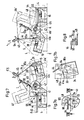
- the bobbin 10 and 10 'each contain a arranged on a bracket-like support member 44, penetrated by an eyelet 43 thread guide element 45 for receiving, holding and releasing the starting piece A of the wound on the supply spool 4 weft 5.
- the support part 44 can be pivoted on the flange parts 33 and 34 about an axis running parallel to the wall part 33 between a basic position in which the thread guide element 45 is located at a radial distance from the supply spool 4 to be accommodated and a deflection position in which the thread guide element 45 at an axial distance from the supply spool 4, in the region of the elongated longitudinal axis L of the spool holder 35.
- the holding parts 41 and 41a are articulated on the bobbin frame 3 so as to be pivotable about an upright axis 46 and can be adjusted with one another via an adjusting device 47 between the first pivot position shown in full lines and a second pivot position shown in dash-dot lines.
- the holding part 41a assumes an operating position which corresponds to an operating position of the associated first coil carrier 10 which is aligned with the common guide element 6, while the holding part 41 assumes a loading position which allows the associated second coil carrier 10 to be replaced more easily.
- the holding part 41 assumes a corresponding operating position 41 'directed against the thread guide member 6, while the holding part 41a assumes a loading position 41a'.
- the adjusting device 47 can, as shown, contain a pneumatic piston / cylinder unit 50 articulated on a support plate 45 of the bobbin frame 3, the piston rod 51 of which can be coupled to the holding parts 41 and 41a via two driver disks 52 and 52a and two drivers 53 and 53a which are adjustable relative to one another .
- the holding parts 41 and 41a can each be decoupled by loosening the driver 53 or 53 'from the driver plate 52 or 52a and manually in the other pivot position and / or - via the
- the loading position can be adjusted to a service position (not shown) that can be taken up in the bobbin train, in which, for example, the inactive, possibly defective, supply spool 4 can be replaced without interrupting the machine operation or a malfunction can be remedied.
- corresponding holding parts are rigidly connected to one another and directly coupled to the or a corresponding adjusting device.
- a single, common holding part can be provided for the coil carrier 10.
- the thread guiding element 45 is held in the suction area of the suction tube 6, the weft thread 5 being drawn off from the supply spool 4.
- the holding part 41 held in the loading position lies with the corresponding loading position 41a 'of the holding part 41a in a vertical plane E, which preferably runs parallel to the mounting rails 17, 17a. Accordingly, all of the bobbin frames 3 facing the same transverse aisle can be reached by the loading device 16 in a single assigned loading position of the mounting rails 17, 17a.
- the loading process can be initiated at any time within the relatively long operating phase, during which the weft thread 5 is drawn off from the active supply spool 4.
- the bobbin 10 ' which, according to FIG. 5, is pivoted against the plane E by the holding part 41 during the previous bobbin change from the operating position shown with dash-dotted lines a coil holder 10 equipped with the corresponding new supply spool 4 is removed from the driver 22 and guided against the spool frame 3 via the appropriately controlled charging device 16.
- the holder 30 of the gripping device 28 can be rotated by 180 ° with respect to the illustration according to FIG.
- the holder 30 is released from the coil carrier 10 and the coil carrier 10 located on the holder 30 'is returned by a corresponding return movement of the manipulator arm 24 against the gap formed during the previous removal of the new supply coil 4 in the transport unit 11 and attached to the driver 22.
- a drive part shown in the illustration as a gearwheel 54, arranged on the swivel axis of the bracket-like support part 44 can engage with a fixed adjustment part, which contains a toothed segment 55 or 55a, which is arranged in its swivel area and which, for example, rests on a on the support plate 48 attached bracket 56 may be attached.
- the support part 44 located on the holding part 41 is pivoted from the basic position shown with solid lines into the deflection position shown with dash-dotted lines, in which the thread guide element 45 - in the operating position 41 'of the holding part 41 - enters the inlet area of the suction pipe 6.
- the support part 44 located on the holding part 41a is pivoted back in the region of the toothed segment 55a from the deflection position shown with solid lines into the basic position corresponding to the loading position 41a '.
- a resiliently arranged stop 57 can be provided on the lower flange part 33, which interacts with an adjusting disk 58 mounted on the pivot axis of the support part 44 in a rotationally fixed manner.
- the shim 58 can be provided with recesses 60 and 60 'into which the stop 57 can engage in the respective basic position or in the deflected position of the support part 44 and can block this support part 44.
- a clamping pin 61 arranged in the supporting part 44 and clampable against the starting piece A located in the eyelet 43 can be provided, which in the transfer position of the supporting part 44 assigned to the suction pipe 6 by means of not shown, e.g. means arranged on the support plate 48, possibly via the control device 49, can be adjusted into a release position releasing the weft thread 5, so that the starting piece A of the weft thread 5 can be fed through the suction tube 6 to the weft insertion device, not shown, of the weaving machine.
- the device according to the invention is also suitable for designs with fixed holding parts for the bobbin 10, 10 ', these being placed on or removed from the holding part in question in the operating position aligned with the suction tube 6 or a corresponding thread guide member via the correspondingly controlled loading device 16 will.
- a drivable adjusting element (not shown) corresponding to tooth segment 55 or 55a (FIG. 6) can be provided on the holding parts, which e.g. can be coupled to the gear 54 and via which the support part 44 with the thread guide element 45 is adjustable in the manner described.
- the coil frame 3 can be designed with four holding parts 41 and 41a and 41b and 41c for receiving four coil carriers 10 and 10 '.
- the holding parts 41 and 41a can be adjusted together via the piston / cylinder assembly 50 in the manner already described.
- the holding parts 41b and 41c are adjustable by means of a corresponding piston / cylinder unit 50a, the holding part 41b being between the operating position shown in full lines and a position loading position 41b 'shown with dash-dotted lines, and the holding part 41c are adjustable between the loading position shown with solid lines and an operating position 41c' shown with dash-dotted lines.
- the holding parts 41 and 41a are aligned in their operating positions against the intake manifold 6.
- the holding parts 41b and 41c are aligned in their operating positions against a second suction pipe 6a.
- the two suction tubes 6 and 6a are aligned symmetrically to one another against a common guide element, not shown, of the weaving machine, for example a guide eye connected upstream of a thread store. Accordingly, as is known, the weft thread 5 to be inserted can optionally be drawn off from one of the respectively active supply spools 4.
- the holding parts 40 and 41a or 41b and 41c, each coupled to the same piston / cylinder unit 50 or 50a are at different pivoting angles between the respective charging position in the common plane E and the relevant operating position pivotable.
- the thread guide elements 45 containing support parts 44 can, as shown in particular in Fig. 8, each with a rotatably arranged on the pivot axis crank-like drive part with a bobbin from the relevant bobbin 10 or 10 'protruding downwards 64, which for Merging with an adjusting part 65 or 65a arranged in its swivel range is determined.
- the adjusting parts 65 and 65a can each be formed by a guide plate which can be fastened to the support plate 48 and which has a guide path 66 or 41 corresponding to the pivoting angle of the associated holding part 41, 41c or 41a, 41b. 66a for the guide pin 64 protruding from the coil carrier 10 or 10 '.
- the carrying part 44 which is guided through the guide track 65 and is located on the holding part 41 or 41c, moves from the illustrated basic position towards the inlet area of the suction pipe 6 or 6a, while the support part 44, which is guided through the guide track 65a and is located on the holding part 41a or 41b, is returned from the illustrated deflection position into the corresponding basic position, not shown.
- the device according to the invention enables the transport spools 4 to be transported gently and to replace the empty spool sleeves 4a with the new supply spools 4 in a way that can be automated with little effort, and a rapid transition from the active spool to the reserve spool.
- the device according to the invention can preferably be used in connection with a device for the automatic removal of an incorrectly entered weft thread.
- a device for the automatic removal of an incorrectly entered weft thread Such, e.g.
- the end piece of the weft thread running from the active bobbin can be regarded as a defective weft and removed from the shed, whereupon the weft thread of the reserve bobbin provided by the device according to the invention has no notable value Delay can be entered in the shed.
- the holding parts 41, 41a articulated independently of one another on the axis 46 and each can be coupled in an adjustable manner between the operating position and a loading position with the adjusting device 47 - or with adjusting means of any other type.
- Corresponding holding parts can also be articulated on the bobbin frame 3 on each of their own pivot axes and can be locked.
- the articulation points on the holding parts can be arranged, for example, in such a way that the pivot axes, which are intended to be extended, each run approximately through the center of gravity of the supply spool 4, which is not shown.
- An embodiment is also possible in which the coil carriers 10 are attached to the coil frame 3 so that they can be suspended.
- the bobbin supports can also each be designed with a fixed thread guide element, which can be arranged, for example, on a support part which projects rigidly from the bobbin in question and can be guided against the inlet region of the thread guide member 6.
- corresponding coil carriers 10 can also each be provided with two or more coil holders 38 arranged next to or above one another for a corresponding number of supply coils 4.
- the threads of the supply bobbins 4 located on the same bobbin 10 can each be outside the weaving room, e.g. in the preparation station 8, and the beginning of the thread of the one, e.g. lowest supply spool 4 can be inserted into the thread guide element 45.
- This embodiment makes it possible to provide a multiple of the weft thread supply which can be supplied by previous devices in each case during a loading process. This version is therefore particularly advantageous in connection with weaving machines for high weft insertion rates.
Landscapes
- Engineering & Computer Science (AREA)
- Textile Engineering (AREA)
- Looms (AREA)
- Auxiliary Weaving Apparatuses, Weavers' Tools, And Shuttles (AREA)
Applications Claiming Priority (2)
| Application Number | Priority Date | Filing Date | Title |
|---|---|---|---|
| CH145691 | 1991-05-15 | ||
| CH1456/91 | 1991-05-15 |
Publications (2)
| Publication Number | Publication Date |
|---|---|
| EP0514322A1 true EP0514322A1 (fr) | 1992-11-19 |
| EP0514322B1 EP0514322B1 (fr) | 1995-05-24 |
Family
ID=4210894
Family Applications (1)
| Application Number | Title | Priority Date | Filing Date |
|---|---|---|---|
| EP92810270A Expired - Lifetime EP0514322B1 (fr) | 1991-05-15 | 1992-04-09 | Dispositif pour alimenter un métier à tisser en bobines de réserve de fil de trame et procédé pour actionner le dispositif |
Country Status (4)
| Country | Link |
|---|---|
| US (1) | US5247969A (fr) |
| EP (1) | EP0514322B1 (fr) |
| JP (1) | JPH05148745A (fr) |
| DE (1) | DE59202295D1 (fr) |
Families Citing this family (1)
| Publication number | Priority date | Publication date | Assignee | Title |
|---|---|---|---|---|
| FR2682094B1 (fr) * | 1991-10-02 | 1995-04-14 | Superba Sa | Ratelier pour supporter des bobines de fil textile. |
Citations (4)
| Publication number | Priority date | Publication date | Assignee | Title |
|---|---|---|---|---|
| EP0144652A2 (fr) * | 1983-11-17 | 1985-06-19 | Burlington Industries, Inc. | Râtelier à plusieurs modules |
| EP0225670A1 (fr) * | 1985-12-09 | 1987-06-16 | Picanol N.V. | Procédé et dispositif pour dérouler un fil d'une bobine dans les métiers à tisser |
| EP0404717A1 (fr) * | 1989-06-20 | 1990-12-27 | GebràDer Sulzer Aktiengesellschaft | Métier à tisser avec bobine de trame mobile |
| EP0421362A1 (fr) * | 1989-10-04 | 1991-04-10 | Tsudakoma Kogyo Kabushiki Kaisha | Dispositif pour relier les fils de deux bobines d'alimentation en fil de trame |
Family Cites Families (5)
| Publication number | Priority date | Publication date | Assignee | Title |
|---|---|---|---|---|
| CA1317853C (fr) * | 1987-06-16 | 1993-05-18 | Ichikawa Woolen Textile Co., Ltd. | Appareil de remplacement automatique des tubes pour metier a tisser et a navette |
| IT1222730B (it) * | 1987-09-25 | 1990-09-12 | Savio Spa | Metodo ed apparecchio per la rimozione di bobine di filato e loro deposito in un carrello a pioli |
| JPH0210478A (ja) * | 1988-06-28 | 1990-01-16 | Nec Corp | プログラムテーブルインタフェース回路 |
| US5000231A (en) * | 1988-10-11 | 1991-03-19 | Tsudakoma Kogyo Kabushiki Kaisha | Automatic weft yarn package changing system |
| JPH02104745A (ja) * | 1988-10-11 | 1990-04-17 | Tsudakoma Corp | 織機と給糸体自動交換方法と、それに使用する織機の給糸体スタンド装置 |
-
1992
- 1992-04-09 DE DE59202295T patent/DE59202295D1/de not_active Expired - Fee Related
- 1992-04-09 EP EP92810270A patent/EP0514322B1/fr not_active Expired - Lifetime
- 1992-05-14 US US07/883,599 patent/US5247969A/en not_active Expired - Fee Related
- 1992-05-15 JP JP4123878A patent/JPH05148745A/ja active Pending
Patent Citations (4)
| Publication number | Priority date | Publication date | Assignee | Title |
|---|---|---|---|---|
| EP0144652A2 (fr) * | 1983-11-17 | 1985-06-19 | Burlington Industries, Inc. | Râtelier à plusieurs modules |
| EP0225670A1 (fr) * | 1985-12-09 | 1987-06-16 | Picanol N.V. | Procédé et dispositif pour dérouler un fil d'une bobine dans les métiers à tisser |
| EP0404717A1 (fr) * | 1989-06-20 | 1990-12-27 | GebràDer Sulzer Aktiengesellschaft | Métier à tisser avec bobine de trame mobile |
| EP0421362A1 (fr) * | 1989-10-04 | 1991-04-10 | Tsudakoma Kogyo Kabushiki Kaisha | Dispositif pour relier les fils de deux bobines d'alimentation en fil de trame |
Non-Patent Citations (1)
| Title |
|---|
| PATENT ABSTRACTS OF JAPAN vol. 14, no. 310 (C-736)(4253) 4. Juli 1990 & JP-A-2 010 478 ( TSUDAKOMA CORP ) 17. April 1990 * |
Also Published As
| Publication number | Publication date |
|---|---|
| EP0514322B1 (fr) | 1995-05-24 |
| US5247969A (en) | 1993-09-28 |
| DE59202295D1 (de) | 1995-06-29 |
| JPH05148745A (ja) | 1993-06-15 |
Similar Documents
| Publication | Publication Date | Title |
|---|---|---|
| DE3348031C2 (fr) | ||
| DE3872476T2 (de) | Verfahren und vorrichtung zum abnehmen von garnspulen und zum ablegen dieser spulen in einen spulenwagen. | |
| EP1428783B1 (fr) | Méthode et dispositif de mise en service d'un poste de travail d'une machine textile pour la fabrication de bobines à spires croisées | |
| EP0310871B1 (fr) | Procédé et dispositif pour échanger automatiquement des bobines de mèche dans un continu à filer à anneaux | |
| DE2939675A1 (de) | Spulenwechseleinrichtung fuer textilmaschinen | |
| DE3448097C2 (fr) | ||
| DE3208677C2 (fr) | ||
| DE3325999C2 (fr) | ||
| DE3485940T2 (de) | Vorrichtung zum einlegen von spulenhuelsen. | |
| DE3630214C2 (fr) | ||
| DD299664A5 (de) | Betriebsverfahren und vorrichtung zum automatisierten auswechseln von auflaufspulen, insbesondere zwirnkreuzspulen, gegen leere aufwickelhuelsen | |
| DE2811128C2 (de) | Automatische Spulenwechselvorrichtung | |
| DE2620428A1 (de) | Offenend-spinnmaschine mit einer verfahrbaren vorrichtung zum entnehmen von vollen spulen und zum einsetzen von zu bespulenden huelsen | |
| DE102007036696A1 (de) | Kreuzspulenwechsler | |
| DE3819873C2 (fr) | ||
| EP0979791A2 (fr) | Machine textile fabricant des bobines croisées | |
| EP1127831B1 (fr) | Dispositif de mise en service d'un poste de travail d'une machine textile pour la fabrication de bobines à spires croisées | |
| DE69024579T2 (de) | Vorrichtung zur Herstellung einer Verbindung zwischen Fäden verschiedener Schussfadenvorratsspulen | |
| DE102020111766A1 (de) | Transportsystem zur Bereitstellung von Vorlagespulen | |
| EP1197463B1 (fr) | Dispositif pour amener des noyaux au poste de travail d'une machine textile pour la fabrication de bobines à spires croisées | |
| EP0514321B1 (fr) | Dispositif pour transporter et manipuler des bobines de réserve de fil de trame ainsi que les amener aux cantres des métiers à tisser et procédé pour actionner le dispositif | |
| DE68920686T2 (de) | Vorrichtung zum Austauschen einer Garnspule und Verfahren zum Austauschen einer Garnspule für eine Webmaschine. | |
| EP0514322B1 (fr) | Dispositif pour alimenter un métier à tisser en bobines de réserve de fil de trame et procédé pour actionner le dispositif | |
| DE3800186A1 (de) | Verfahren zur belieferung des bedienungswerkes einer textilmaschine mit leeren spulhuelsen, sowie vorrichtung zum durchfuehren dieses verfahrens | |
| DE4233819C2 (de) | Verfahren zum Betreiben einer automatischen Spulmaschine bei Partiewechsel |
Legal Events
| Date | Code | Title | Description |
|---|---|---|---|
| PUAI | Public reference made under article 153(3) epc to a published international application that has entered the european phase |
Free format text: ORIGINAL CODE: 0009012 |
|
| AK | Designated contracting states |
Kind code of ref document: A1 Designated state(s): BE DE FR IT |
|
| 17P | Request for examination filed |
Effective date: 19930326 |
|
| 17Q | First examination report despatched |
Effective date: 19940907 |
|
| RAP1 | Party data changed (applicant data changed or rights of an application transferred) |
Owner name: SULZER RUETI AG |
|
| GRAA | (expected) grant |
Free format text: ORIGINAL CODE: 0009210 |
|
| AK | Designated contracting states |
Kind code of ref document: B1 Designated state(s): BE DE FR IT |
|
| PG25 | Lapsed in a contracting state [announced via postgrant information from national office to epo] |
Ref country code: IT Free format text: LAPSE BECAUSE OF FAILURE TO SUBMIT A TRANSLATION OF THE DESCRIPTION OR TO PAY THE FEE WITHIN THE PRESCRIBED TIME-LIMIT;WARNING: LAPSES OF ITALIAN PATENTS WITH EFFECTIVE DATE BEFORE 2007 MAY HAVE OCCURRED AT ANY TIME BEFORE 2007. THE CORRECT EFFECTIVE DATE MAY BE DIFFERENT FROM THE ONE RECORDED. Effective date: 19950524 Ref country code: FR Effective date: 19950524 Ref country code: BE Effective date: 19950524 |
|
| REF | Corresponds to: |
Ref document number: 59202295 Country of ref document: DE Date of ref document: 19950629 |
|
| EN | Fr: translation not filed | ||
| PLBE | No opposition filed within time limit |
Free format text: ORIGINAL CODE: 0009261 |
|
| 26N | No opposition filed | ||
| PG25 | Lapsed in a contracting state [announced via postgrant information from national office to epo] |
Ref country code: DE Effective date: 19970101 |