EP0514567A1 - Mécanisme d'éjection de l'equipage d'un avion - Google Patents
Mécanisme d'éjection de l'equipage d'un avion Download PDFInfo
- Publication number
- EP0514567A1 EP0514567A1 EP91108255A EP91108255A EP0514567A1 EP 0514567 A1 EP0514567 A1 EP 0514567A1 EP 91108255 A EP91108255 A EP 91108255A EP 91108255 A EP91108255 A EP 91108255A EP 0514567 A1 EP0514567 A1 EP 0514567A1
- Authority
- EP
- European Patent Office
- Prior art keywords
- forebody
- fuel tank
- crew
- vehicle
- main vehicle
- Prior art date
- Legal status (The legal status is an assumption and is not a legal conclusion. Google has not performed a legal analysis and makes no representation as to the accuracy of the status listed.)
- Granted
Links
- 230000007246 mechanism Effects 0.000 title description 5
- 239000002828 fuel tank Substances 0.000 claims abstract description 44
- 238000002485 combustion reaction Methods 0.000 claims abstract description 9
- 238000000926 separation method Methods 0.000 claims description 43
- 230000005484 gravity Effects 0.000 claims description 16
- 239000000446 fuel Substances 0.000 claims description 9
- 238000005474 detonation Methods 0.000 claims description 5
- 230000000087 stabilizing effect Effects 0.000 claims description 5
- 230000004913 activation Effects 0.000 claims description 2
- 230000004044 response Effects 0.000 claims description 2
- 230000003213 activating effect Effects 0.000 claims 1
- 239000002360 explosive Substances 0.000 claims 1
- 238000004880 explosion Methods 0.000 abstract description 16
- 239000003380 propellant Substances 0.000 abstract description 10
- 230000000694 effects Effects 0.000 abstract description 3
- 238000010276 construction Methods 0.000 abstract description 2
- 239000000463 material Substances 0.000 abstract description 2
- 230000001052 transient effect Effects 0.000 abstract description 2
- 239000002775 capsule Substances 0.000 description 9
- 235000015842 Hesperis Nutrition 0.000 description 3
- 235000012633 Iberis amara Nutrition 0.000 description 3
- 238000001816 cooling Methods 0.000 description 3
- 238000000605 extraction Methods 0.000 description 3
- OAKJQQAXSVQMHS-UHFFFAOYSA-N Hydrazine Chemical compound NN OAKJQQAXSVQMHS-UHFFFAOYSA-N 0.000 description 2
- 230000001133 acceleration Effects 0.000 description 2
- 238000010438 heat treatment Methods 0.000 description 2
- 230000001939 inductive effect Effects 0.000 description 2
- 238000000034 method Methods 0.000 description 2
- 239000011295 pitch Substances 0.000 description 2
- 239000012080 ambient air Substances 0.000 description 1
- 230000007613 environmental effect Effects 0.000 description 1
- 231100001261 hazardous Toxicity 0.000 description 1
- 239000007788 liquid Substances 0.000 description 1
- 238000012986 modification Methods 0.000 description 1
- 230000004048 modification Effects 0.000 description 1
- 239000007800 oxidant agent Substances 0.000 description 1
- 230000006641 stabilisation Effects 0.000 description 1
- 238000011105 stabilization Methods 0.000 description 1
Images

Classifications
-
- B—PERFORMING OPERATIONS; TRANSPORTING
- B64—AIRCRAFT; AVIATION; COSMONAUTICS
- B64D—EQUIPMENT FOR FITTING IN OR TO AIRCRAFT; FLIGHT SUITS; PARACHUTES; ARRANGEMENT OR MOUNTING OF POWER PLANTS OR PROPULSION TRANSMISSIONS IN AIRCRAFT
- B64D25/00—Emergency apparatus or devices, not otherwise provided for
- B64D25/08—Ejecting or escaping means
- B64D25/12—Ejectable capsules
Definitions
- This invention relates to an aircraft protection system, and is particularly concerned with a crew protection system for safely evacuating aircraft, especially hypersonic vehicles, in emergency situations, e.g. in the event of an uncommanded failure or explosion of the main fuel tank.
- the prior art to date has failed to address the problem of protecting the crew of an aircraft from the effects of a sudden overpressure created by a catastrophic failure of the main vehicle fuel or propellant tank.
- the prior art deals mainly with commanded or dedicated systems for removing the crew compartment from the remainder of an aircraft vehicle in an emergency, but fails to deal with means to activate or initiate crew member escape systems due to the uncommanded catastrophic failure of the vehicle resulting from a propellant tank explosion.
- existing crew protection concepts impose unacceptable weight penalties and are not cost efficient.
- U. S. Patent 4,580,746 discloses a capsule and rocket extraction system for providing an inflight escape system for the pilot of a damaged aircraft, comprising means for sequentially actuating a capsule extraction device to separate the capsule from the main fuselage and then actuating a rocket for extracting the pilot from the capsule.
- Each of the above patented escape systems specifies a propulsion unit for crew compartment separation.
- the prior art deals with dedicated extraction systems such as dedicated rockets to activate crew member escape systems.
- Another object is the provision of a crew protection system for aircraft in the event of an uncommanded catastrophic failure or explosion of the main fuel tank.
- a still further object is the provision of means to permit crew members to escape from aerospace vehicles, by permitting the crew-containing capsule to be thrust clear from the remainder of the vehicle, in an emergency situation resulting from an uncommanded failure or detonation of the main fuel tank, thereby providing a weight savings over prior art methods of crew protection, such as the use of dedicated rockets, particularly at hypersonic speeds.
- the crew protection system of the invention is designed to isolate the crew of the aircraft from hazards particularly catastrophic failure of the fuel tank, and provides a means for safely evacuating hypersonic vehicles in such emergency situations.
- the crew compartment is positioned within a forebody of the main vehicle.
- the forebody is designed so as to separate cleanly from the main vehicle in the event of catastrophic failure of the main vehicle fuel tank, as by combustion of propellants, protecting the crew members throughout such hazardous situation.
- the forebody separation system will generate a simultaneous substantially circumferential structural break during a catastrophic tank explosion. This system will allow the energy released by such fuel tank failure to separate the forebody from the parent vehicle without any lagging structural detachments. This will assure that the forebody separates from the parent vehicle without inducing any undesirable pitching or yawing moments.
- the forebody In the event of an uncommanded failure of the main tank, propellant combustion and the resultant pressure impulse, thrusts the forebody clear from the remainder of the vehicle.
- the forebody is designed to withstand the worst case, uncommanded, failure modes.
- the invention system is unique in that it protects the crew members during situations where there is insufficient lead time to initiate escape.
- separation of the forebody from the main vehicle does not require a dedicated rocket motor for separation, a considerable weight savings is gained, and the invention system is thus cost efficient.
- the shape and physical characteristics of the forebody and the materials used in its construction mitigate the effects of the blast pressure impulse.
- the forebody protects the crew members from both the heat of the blast and the aerodynamic heating experienced during the subsequent ballistic trajectory.
- the forebody is designed to be stable during both the transient period immediately following the blast and the subsequent freefall conditions. In the event of a high altitude/high speed escape situation, the crew members would ride down in the forebody to a lower altitude. At a preselected altitude and terminal velocity, the crew could then evacuate the forebody using a conventional ejection seat.
- the forebody separation concept of the invention employs a tank blast overpressure to separate and propel the forebody from the main vehicle.
- the separation device employs predictable failure of the primary structure to cleanly cut the fuselage and separate the forebody.
- numeral 10 represents a hypersonic aircraft having a forebody or forebody capsule 12 and an aft fuselage 14.
- the forebody 12 contains a crew compartment 16 having an ejection seat 18 of conventional design.
- the forebody consists of a blastworthy structure to provide protection from a catastrophic structural failure resulting from a fuel tank explosion.
- baffles including a crew compartment pressure bulkhead 20 and an aft pressure bulkhead 22 are provided, with an avionics bay 24 located between the bulkheads and aft of the crew compartment 16.
- a fuel or propellant tank 26 is located in the fuselage 14, just aft of the forebody 12.
- the fuel tank 26 contains baffles such as 28 and an end cap 30 just aft of the avionics bay pressure bulkhead 22.
- the baffles such as 28 within the main fuel tank 26, the end cap 30 on the fuel tank, and the forebody bulkheads 20 and 22, are designed to protect the crew member from the hazards of a main tank failure.
- An attitude control system 32 is provided in the forebody 12 to afford a very rapid means of stabilizing the forebody once activated during escape following forebody separation.
- Environmental control and life support system 34 is also provided. Thermodynamic heating of the forebody vehicle limits the performance envelope of the forebody for escape, unless provisions are made for cooling.
- an active cooling system indicated at 37 is provided in the nose 36 of the forebody.
- the ejection seat 18 provides a means of evacuating the forebody in the event of low altitude, low speed escape situations and can also be used to evacuate the crew compartment and forebody after separation thereof from the main vehicle, following a catastrophic fuel tank explosion.
- Fig. 3 there is shown one embodiment of a completely passive separation system of the invention which would allow the forebody to separate from the parent vehicle by relying entirely on blast overpressures to provide a clean structural break.
- Numerals 38 and 40 illustrate the primary structural members between the forebody 12 and main fuselage 14, just aft of the fuel tank end cap 30.
- the primary structural members 38 and 40 are connected together at their separation plane 42 by a plurality, here shown as two, joint fasteners 44.
- a joint guillotine 46 is provided on a support member 48, the guillotine 46 being connected to a pressure sensing mechanism (not shown) which activates the guillotine to sever the structural fasteners 44, upon the application of a predetermined overpressure such as that from a catastrophic fuel tank explosion, which is sensed by the pressure sensing mechanism, severing the structural fasteners 44, and separating the primary structure members 38 and 40 and the associated forebody 12 and fuselage 14, along the separation plane 42.
- a plurality of the guillotine type separation systems illustrated in Fig. 3 are provided in equally spaced relation peripherally around the separation plane 42, for simultaneous activation to generate a simultaneous circumferential structural break on the separation plane 42 during a catastrophic tank explosion.
- This system will allow the forebody to separate from the parent vehicle fuselage 14 without any lagging structural detachments. This will assure that the forebody separates from the parent vehicle without inducing any undesirable pitching or yawing moments. This type of structural break thus provides a "clean" separation of the forebody from the main fuselage.
- Another means of detaching the forebody during a catastrophic explosion without relying on crew response can utilize a pressure sensing device which would activate pyrotechnic devices or other systems to provide a clean structural break between the forebody and the main fuselage.
- the aerodynamic or streamlined shape of the forebody 12 and control of the location of the forebody center of gravity are important to provide stability and control of the forebody, after separation from the main fuselage.
- Roll control and attitude stabilization is provided by the attitude control system (ACS) 32.
- An additional stability device for the forebody can also be employed if desired, such as a deployable forebody flap or a drogue chute.
- baffles such as 28 within the fuel tank 26, the tank end cap 30 and bulkheads 20 and 22 within the forebody 12, are designed to mitigate the blast associated with the combustion of the onboard propellant to prevent the acceleration of the crew member from exceeding human limitations.
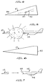
- FIG. 6 showing the separated forebody 12 following the explosion illustrated in Fig. 5, it will be noted that the separation from the main fuselage 14 has taken place along the separation plane 42, providing a "clean" break of the forebody away from the fuselage.
- Fig. 7 illustrating the positions of the forebody 12 and fuselage 14 immediately following separation, once the pressure impulse thrusts the forebody 12 clear of the remainder of the vehicle 14, the relative separation continues to increase due to aerodynamic forces.
- the forebody is streamlined to have a higher ballistic coefficient than the remainder of the vehicle once the forebody has separated.
- the remainder of the vehicle 14 then decelerates at a more rapid rate than does the forebody.
- the open end 53 of the fuselage 14, as shown in Fig. 7, greatly increases drag, and the engine (shut down after the explosion) plus drag pitches the vehicle and aids separation.
- the wing 54 adds lift and drag until it fails.
- Control of the forebody 12 during descent can be implemented through the use of the attitude control system 32 and careful design of the forebody center of gravity 50 with respect to the center of pressure 52.
- the forebody can be stabilized at a slight angle of attack without the necessity of specialized deployable surfaces.
- Small nose jets (not shown) in the nose 36 of the forebody aid in descending to a safe ejection flight regime.
- a shaped charge 56 can optionally be provided externally on vehicle 10 adjacent the separation plane 42. Accelerometers and strain gauges throughout the vehicle continuously monitor pitch and roll rates and the status of the vehicle structure. If it has been determined that a catastrophic vehicle failure is imminent or has occurred, the escape system of the invention is activated by actuation of the charge 56 from the crew compartment, causing a controlled detonation of the propellant in tank 26, ensuring a clean severance and a positive separation between the forebody and the remainder of the fuselage along a substantially circumferential structural break therebetween. If detonation in the tank 26 has previously occurred, the separation charge serves to clean off the aft end of the forebody.
- the present invention provides a simple and practical means for crew members to escape from aerospace vehicles travelling at varying speeds, in the event of an uncommanded failure of the main fuel tank by propellant combustion or explosion, and provides a weight savings over prior art proposed methods of crew protection utilizing commanded systems such as rockets for separating crew member capsules from the main vehicle.
Landscapes
- Business, Economics & Management (AREA)
- Emergency Management (AREA)
- Engineering & Computer Science (AREA)
- Aviation & Aerospace Engineering (AREA)
- Emergency Lowering Means (AREA)
Priority Applications (1)
| Application Number | Priority Date | Filing Date | Title |
|---|---|---|---|
| DE1991606694 DE69106694T2 (de) | 1991-05-22 | 1991-05-22 | Rettungsapparat für Flugzeugbesatzung. |
Applications Claiming Priority (1)
| Application Number | Priority Date | Filing Date | Title |
|---|---|---|---|
| US07/476,849 US5058830A (en) | 1990-02-08 | 1990-02-08 | Escape mechanism for crew of aircraft |
Publications (2)
| Publication Number | Publication Date |
|---|---|
| EP0514567A1 true EP0514567A1 (fr) | 1992-11-25 |
| EP0514567B1 EP0514567B1 (fr) | 1995-01-11 |
Family
ID=23893502
Family Applications (1)
| Application Number | Title | Priority Date | Filing Date |
|---|---|---|---|
| EP91108255A Expired - Lifetime EP0514567B1 (fr) | 1990-02-08 | 1991-05-22 | Mécanisme d'éjection de l'equipage d'un avion |
Country Status (2)
| Country | Link |
|---|---|
| US (1) | US5058830A (fr) |
| EP (1) | EP0514567B1 (fr) |
Families Citing this family (1)
| Publication number | Priority date | Publication date | Assignee | Title |
|---|---|---|---|---|
| US8727283B2 (en) | 2011-06-07 | 2014-05-20 | Aerojet Rocketdyne Of De, Inc. | Launch abort and orbital maneuver system |
Citations (4)
| Publication number | Priority date | Publication date | Assignee | Title |
|---|---|---|---|---|
| US3703265A (en) * | 1970-10-30 | 1972-11-21 | Manuel Lopez Troitino | Aircraft with separable cockpit |
| US3979005A (en) * | 1974-05-13 | 1976-09-07 | The Boeing Company | Cryogenic tank and aircraft structural interface |
| US4580746A (en) * | 1983-05-31 | 1986-04-08 | Stencel Aero Engineering Corporation | Capsule and rocket extraction system |
| GB2200877A (en) * | 1987-02-10 | 1988-08-17 | Zinovi Levin | Crew safety device for spacecraft and aeroplanes. joints for booster rocket segments |
Family Cites Families (8)
| Publication number | Priority date | Publication date | Assignee | Title |
|---|---|---|---|---|
| US2736523A (en) * | 1952-01-02 | 1956-02-28 | Fairey Aviat Co Ltd | Sectional fuselage for aircraft |
| US2977080A (en) * | 1955-05-04 | 1961-03-28 | Zborowski Helmut Ph G A R Von | Aircraft having a detachable cabin |
| US3129667A (en) * | 1960-08-29 | 1964-04-21 | Wen Lian-Tong | Hypersonic cooling device |
| US3067973A (en) * | 1961-03-15 | 1962-12-11 | Donald J Halsey | Ejectable flight capsule |
| GB1022635A (en) * | 1962-07-10 | 1966-03-16 | English Electric Co Ltd | Improvements in or relating to aerial vehicles |
| US3369782A (en) * | 1965-10-05 | 1968-02-20 | Navy Usa | Cooled leading edge |
| IL39260A (en) * | 1972-04-21 | 1975-06-25 | Bouchnik J | Detachable cabin aircraft |
| DE3534719A1 (de) * | 1985-09-28 | 1987-04-02 | Messerschmitt Boelkow Blohm | Druckwand fuer einen unter inneren ueberdruck setzbaren rumpf eines luftfahrzeuges |
-
1990
- 1990-02-08 US US07/476,849 patent/US5058830A/en not_active Expired - Fee Related
-
1991
- 1991-05-22 EP EP91108255A patent/EP0514567B1/fr not_active Expired - Lifetime
Patent Citations (4)
| Publication number | Priority date | Publication date | Assignee | Title |
|---|---|---|---|---|
| US3703265A (en) * | 1970-10-30 | 1972-11-21 | Manuel Lopez Troitino | Aircraft with separable cockpit |
| US3979005A (en) * | 1974-05-13 | 1976-09-07 | The Boeing Company | Cryogenic tank and aircraft structural interface |
| US4580746A (en) * | 1983-05-31 | 1986-04-08 | Stencel Aero Engineering Corporation | Capsule and rocket extraction system |
| GB2200877A (en) * | 1987-02-10 | 1988-08-17 | Zinovi Levin | Crew safety device for spacecraft and aeroplanes. joints for booster rocket segments |
Also Published As
| Publication number | Publication date |
|---|---|
| EP0514567B1 (fr) | 1995-01-11 |
| US5058830A (en) | 1991-10-22 |
Similar Documents
| Publication | Publication Date | Title |
|---|---|---|
| US2941764A (en) | Flaps for supersonic aircraft escape systems | |
| US6776373B1 (en) | Aircraft escape cabin | |
| JP4169132B2 (ja) | 低地球軌道にペイロードを打ち上げるための装置 | |
| US3999728A (en) | Escape vehicle with fly-away capability | |
| US11103392B2 (en) | Safety system for aerial vehicles and method of operation | |
| US3093346A (en) | Space capsule | |
| US4676457A (en) | Aircraft emergency landing system | |
| US10004652B1 (en) | Safety system for aerial vehicles and method of operation | |
| US4721273A (en) | Life-threat assessment and control command for aircrew escape systems | |
| EP0127246B1 (fr) | Système comportant l'extraction par fusée à partir d'une capsule | |
| US4846421A (en) | Adaptive control system for crew escape devices | |
| WO2018156972A1 (fr) | Système de sécurité pour véhicules aériens et procédé de fonctionnement | |
| US5058830A (en) | Escape mechanism for crew of aircraft | |
| US3756546A (en) | Aircrew escape system | |
| JP2627831B2 (ja) | 航空宇宙機 | |
| JP2996479B2 (ja) | 魚雷等のペイロード運搬飛しょう体 | |
| US3807671A (en) | Escape and recovery system | |
| RU2114030C1 (ru) | Скоростной летательный аппарат | |
| CN113955127A (zh) | 一种飞机整体逃逸救生舱 | |
| DE69106694T2 (de) | Rettungsapparat für Flugzeugbesatzung. | |
| PICKL | High performance escape capsules | |
| Blanchard et al. | Full-scale flight test from sea level of an abort-escape system for a Project Mercury capsule | |
| RU2201380C2 (ru) | Устройство для спасения вертолета | |
| JP2026051961A (ja) | 安全装置、および、安全装置を備えた飛行体 | |
| MCMULLEN | Evolution of the B-1 crew escape system |
Legal Events
| Date | Code | Title | Description |
|---|---|---|---|
| PUAI | Public reference made under article 153(3) epc to a published international application that has entered the european phase |
Free format text: ORIGINAL CODE: 0009012 |
|
| AK | Designated contracting states |
Kind code of ref document: A1 Designated state(s): DE FR GB |
|
| 17P | Request for examination filed |
Effective date: 19930507 |
|
| 17Q | First examination report despatched |
Effective date: 19940520 |
|
| GRAA | (expected) grant |
Free format text: ORIGINAL CODE: 0009210 |
|
| AK | Designated contracting states |
Kind code of ref document: B1 Designated state(s): DE FR GB |
|
| ET | Fr: translation filed | ||
| REF | Corresponds to: |
Ref document number: 69106694 Country of ref document: DE Date of ref document: 19950223 |
|
| PLBE | No opposition filed within time limit |
Free format text: ORIGINAL CODE: 0009261 |
|
| STAA | Information on the status of an ep patent application or granted ep patent |
Free format text: STATUS: NO OPPOSITION FILED WITHIN TIME LIMIT |
|
| 26N | No opposition filed | ||
| REG | Reference to a national code |
Ref country code: GB Ref legal event code: IF02 |
|
| PGFP | Annual fee paid to national office [announced via postgrant information from national office to epo] |
Ref country code: FR Payment date: 20020501 Year of fee payment: 12 |
|
| PGFP | Annual fee paid to national office [announced via postgrant information from national office to epo] |
Ref country code: GB Payment date: 20020515 Year of fee payment: 12 |
|
| PGFP | Annual fee paid to national office [announced via postgrant information from national office to epo] |
Ref country code: DE Payment date: 20020520 Year of fee payment: 12 |
|
| PG25 | Lapsed in a contracting state [announced via postgrant information from national office to epo] |
Ref country code: GB Free format text: LAPSE BECAUSE OF NON-PAYMENT OF DUE FEES Effective date: 20030522 |
|
| PG25 | Lapsed in a contracting state [announced via postgrant information from national office to epo] |
Ref country code: DE Free format text: LAPSE BECAUSE OF NON-PAYMENT OF DUE FEES Effective date: 20031202 |
|
| GBPC | Gb: european patent ceased through non-payment of renewal fee |
Effective date: 20030522 |
|
| PG25 | Lapsed in a contracting state [announced via postgrant information from national office to epo] |
Ref country code: FR Free format text: LAPSE BECAUSE OF NON-PAYMENT OF DUE FEES Effective date: 20040130 |
|
| REG | Reference to a national code |
Ref country code: FR Ref legal event code: ST |