EP0514672A1 - Dispositif pour amortir respectivement commander la mise en portefeuille entre les véhicules partiels d'un véhicule articulé - Google Patents
Dispositif pour amortir respectivement commander la mise en portefeuille entre les véhicules partiels d'un véhicule articulé Download PDFInfo
- Publication number
- EP0514672A1 EP0514672A1 EP92106729A EP92106729A EP0514672A1 EP 0514672 A1 EP0514672 A1 EP 0514672A1 EP 92106729 A EP92106729 A EP 92106729A EP 92106729 A EP92106729 A EP 92106729A EP 0514672 A1 EP0514672 A1 EP 0514672A1
- Authority
- EP
- European Patent Office
- Prior art keywords
- sub
- assigned
- vehicle
- vehicles
- slewing
- Prior art date
- Legal status (The legal status is an assumption and is not a legal conclusion. Google has not performed a legal analysis and makes no representation as to the accuracy of the status listed.)
- Granted
Links
- 238000013016 damping Methods 0.000 title claims abstract description 14
- 238000005096 rolling process Methods 0.000 description 3
- 239000012530 fluid Substances 0.000 description 2
- 238000005452 bending Methods 0.000 description 1
- 238000009434 installation Methods 0.000 description 1
- 230000007935 neutral effect Effects 0.000 description 1
Images


Classifications
-
- B—PERFORMING OPERATIONS; TRANSPORTING
- B62—LAND VEHICLES FOR TRAVELLING OTHERWISE THAN ON RAILS
- B62D—MOTOR VEHICLES; TRAILERS
- B62D47/00—Motor vehicles or trailers predominantly for carrying passengers
- B62D47/02—Motor vehicles or trailers predominantly for carrying passengers for large numbers of passengers, e.g. omnibus
- B62D47/025—Motor vehicles or trailers predominantly for carrying passengers for large numbers of passengers, e.g. omnibus articulated buses with interconnecting passageway, e.g. bellows
-
- B—PERFORMING OPERATIONS; TRANSPORTING
- B62—LAND VEHICLES FOR TRAVELLING OTHERWISE THAN ON RAILS
- B62D—MOTOR VEHICLES; TRAILERS
- B62D53/00—Tractor-trailer combinations; Road trains
- B62D53/04—Tractor-trailer combinations; Road trains comprising a vehicle carrying an essential part of the other vehicle's load by having supporting means for the front or rear part of the other vehicle
- B62D53/08—Fifth wheel traction couplings
- B62D53/0871—Fifth wheel traction couplings with stabilising means, e.g. to prevent jack-knifing, pitching, rolling, buck jumping
Definitions
- Articulated vehicles in particular articulated buses, are known in which two sub-vehicles are coupled to one another via a swivel joint, one of which is supported on the rear end of the preceding sub-vehicle and the other of which is assigned to the front end of the following sub-vehicle and is supported in the first-mentioned slewing ring.
- dampers are installed between the two sub-vehicles.
- the damping device has worked with two damping cylinders, each of which counteracts a pivoting movement of the one sub-vehicle relative to the other sub-vehicle in one direction.
- pivoting movements can be damped, blocked or brought about according to a desired law.
- one of the two slewing rings has a toothing which is in engagement with a counter toothing which is assigned to the other slewing ring and their adjustability must be released, braked or prevented.
- the inner of the two concentrically arranged slewing rings can have an internal toothing which interacts with a gearwheel in the free space enclosed by both slewing rings; that is in operative connection with the second of the partial vehicles.
- the gearwheel can interact with a toothed rack which interacts with an actuating cylinder arrangement or a hydraulic motor which is operatively connected to the second sub-vehicle or the second turntable.
- the outer slewing ring, gearwheel and optionally rack with actuating cylinder arrangement or hydraulic motor are preferably arranged on a common base or fastening plate.
- one of the two slewing rings is assigned a toothing which is in engagement with a counter toothing which is assigned to the other slewing ring in such a way that it is arranged at one end of a two-armed lever, the other end of which is about a vertical Axis is pivotally articulated on the cylinder of a piston-cylinder arrangement and is pivotable between its two ends about the vertical axis of a joint which is assigned to a component connected to the other of the two turntables, on which the two outer ends of the piston rods are also articulated, their inner ends are assigned to the piston of the piston-cylinder arrangement.
- Another object of the invention is therefore to modify the proposed solutions so that the damping or control device is easily accessible in order to be easily assembled, disassembled and serviced.
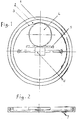
- FIG. 1 A device according to the invention is shown schematically in the drawing, specifically in FIG. 1 as a top view and in FIG. 2 as a section along the line II-II in FIG. 1.
- Embodiments of the invention are shown schematically in the drawing and explained below, which is a first embodiment shown in Figure 1 as a plan view and in Figure 2 as a side view. it is the subject of claims 1 to 4, a second embodiment is shown in Figure 3 as a plan view and in Figure 4 as a section along the line II - II in Fig. 3. it is the subject of claims 1 and 5, a third embodiment shown in Figure 5 as a plan view and in Figure 6 as a section along the line II - II in Fig. 5. it is the subject of claims 1 and 6 to 8.
- the swivel joint has an outer ring or slewing ring 1 of the one sub-vehicle and an inner ring or slewing ring 2 of the second sub-vehicle.
- the ring assigned to the front sub-vehicle is supported on it if it usually has axles or wheels at both ends.
- the ring assigned to the rear sub-vehicle is supported on this ring when it is mounted on the front sub-vehicle in the usual way.
- the rotary movements between the two rings are possible by means of rolling elements symbolically represented in the drawing.
- the inner ring 2 is now provided with an internal toothing 3, which can be designed as an endlessly rotating ring gear or as a ring gear segment.
- a toothed wheel 4 interacts with this internal toothing 3.
- This gear 4 cooperates with a rack 5, which is firmly connected to the housing of a hydraulic cylinder or a hydraulic motor.
- Hydraulic cylinder or motor is designated 6 in its entirety.
- the hydraulic cylinder 6 is constructed in a conventional manner, ie a piston enclosing throttle bores is arranged in its interior filled with a fluid, on each side of which one of the two piston rods is attached, which is led out of both housing ends. If a hydraulic motor is to be used, a hydraulic motor with a corresponding function is used.
- the hydraulic cylinder can have several individual hydraulic cylinders arranged one behind the other, if the forces and installation conditions to be controlled make this seem more expedient.
- the outer ends of the piston rods are hinged to a base or fastening plate 7, which in turn is fastened to the outer of the two rings 1, 2.
- the swivel joint has an outer ring or slewing ring 1 of the one sub-vehicle and an inner ring or slewing ring 2 of the second sub-vehicle.
- the ring assigned to the front sub-vehicle is supported on it if it usually has axles or wheels at both ends.
- the ring assigned to the rear sub-vehicle is supported on this ring when it is mounted on the front sub-vehicle in the usual way.
- a third ring can be arranged between these two rings.
- the rotary movements between the rings are possible by means of roller bearings 3 shown symbolically in the drawing.
- the inner ring 2 is now assigned a toothed segment 4 with an internal toothing, which can also be designed as an endlessly rotating ring gear.
- a toothing 5 interacts with this internal toothing of the toothed segment 4.
- This toothing 5 forms as an external toothing a part of the outer circumference of a pivotable lever 6, which has two arms, the lever 6 is pivotally mounted in two spaced apart bearings 8, 9 around a vertical pin 7. At the outer end of one arm of this lever, the aforementioned external toothing 5 is attached. At the outer end of the other arm of the two-armed lever 6, this is pivotally mounted on a vertical pin 10.
- the bearing pin 7 is attached at the lower end to the top of a horizontal base plate 11, which runs under the entire arrangement, is guided radially outwards under the inner ring 2 and is attached with its outer end to the underside of the outer ring 1.
- the vertical pin 10 is fastened at its lower end to the top of a cylinder 12, which is arranged in the free space enclosed by the rings 1, 2 approximately in a plane of diameter of the two rings.
- the longitudinal axis 13 of the cylinder 12 and the connecting line 14 of the two pins 7 and 10 intersect at an angle of 90 ° and the toothings 4, 5 are symmetrical on the line 14 both sides.
- the cylinder 12 encloses a piston 15 of the two hydraulic spaces within the cylinder 12, which are connected to one another by throttle bores in the piston 15 and / or are connected in a controlled manner to hydraulic reservoirs (not shown).
- a piston rod 16 or 17 is assigned to the piston 15 on both sides.
- One of the two piston rods 16, 17 is led out of one of the two piston end faces and the outer ends of the two piston rods are connected to the base plate 11 and articulated thereon in a "rotatable cylinder receptacle" 18.
- Essential to the invention is the arrangement of the cylinder via two central pins on the piston and on the cylinder, i.e. the pin 10 between the lever 6 and the cylinder 12 and the pin 18 between the ends of the continuous piston rod 16, 17 and the base plate 11.
- the swivel joint has an outer ring or slewing ring 1 of the one sub-vehicle 2 following when driving forward and an inner ring or slewing ring 3 of the second sub-vehicle 4 which is forward when driving forward.
- the ring 3 assigned to the front sub-vehicle 4 is supported thereon if it usually has axles or wheels at both ends.
- the ring assigned to the rear sub-vehicle 2 is supported on this ring 3 when it is mounted on the front sub-vehicle in the usual way.
- Rotary movements between the two horizontally lying rings are possible by rolling elements, not shown.
- a platform 5 which is rigid and rigidly connected is attached, at the front end of which are arranged symmetrically to the longitudinal axis 6 of the vehicle (top view and straight travel assumed), two eyes 7, 8, which are rotatable on two lateral, coaxial horizontal ones Cross pin 9,10 of the outer ring 1 are mounted.
- the use of rubber sleeves allows a slanted position between the longitudinal axis of the eyes 7, 8 on the one hand and the longitudinal axis of the transverse pins 9, 10 on the other hand to allow rolling movements of the two sub-vehicles 2, 4 relative to one another.
- the longitudinal axis 6 and the transverse axis 11 do not intersect at the center of the swivel joint, but rather the transverse axis 11 is moved somewhat to the rear with respect to this center of the swivel joint (which coincides with the plan view of the vertical axis 11 in FIG. 5).
- the outer ring 1 is now provided with an external toothing, which may be designed as an endlessly rotating ring gear, but preferably as a ring gear segment.
- a toothed rack 14 cooperates with this external toothing 13 and is firmly connected to the common housing 15 of two parallel and identically acting hydraulic cylinders 16, 17.
- Each of the hydraulic cylinders is constructed in the usual way, i.e. In its interior filled with a fluid, a piston enclosing throttle bores is arranged, on each side of which one of the two piston rods 18, 19 is attached, which is led out of both housing ends.
- the hydraulic cylinder is pivotable about a vertical pin 20, which is attached to a rigid and rigidly connected platform 21 at the rear end of the vehicle 4 in front, to which the outer ends of the piston rods 18, 19 are also attached and finally at the outer end of the platform part 21a carries the inner ring 3.
Landscapes
- Engineering & Computer Science (AREA)
- Chemical & Material Sciences (AREA)
- Combustion & Propulsion (AREA)
- Transportation (AREA)
- Mechanical Engineering (AREA)
- Vehicle Body Suspensions (AREA)
- Steering-Linkage Mechanisms And Four-Wheel Steering (AREA)
- Vibration Prevention Devices (AREA)
- Transmission Devices (AREA)
- Retarders (AREA)
- Vibration Dampers (AREA)
- Mechanical Operated Clutches (AREA)
Applications Claiming Priority (2)
| Application Number | Priority Date | Filing Date | Title |
|---|---|---|---|
| DE4116684 | 1991-05-22 | ||
| DE4116684 | 1991-05-22 |
Publications (2)
| Publication Number | Publication Date |
|---|---|
| EP0514672A1 true EP0514672A1 (fr) | 1992-11-25 |
| EP0514672B1 EP0514672B1 (fr) | 1995-07-19 |
Family
ID=6432168
Family Applications (1)
| Application Number | Title | Priority Date | Filing Date |
|---|---|---|---|
| EP92106729A Expired - Lifetime EP0514672B1 (fr) | 1991-05-22 | 1992-04-20 | Dispositif pour amortir respectivement commander la mise en portefeuille entre les véhicules partiels d'un véhicule articulé |
Country Status (6)
| Country | Link |
|---|---|
| EP (1) | EP0514672B1 (fr) |
| AT (1) | ATE125217T1 (fr) |
| DE (1) | DE59202911D1 (fr) |
| DK (1) | DK0514672T3 (fr) |
| ES (1) | ES2074757T3 (fr) |
| GR (1) | GR3017439T3 (fr) |
Cited By (4)
| Publication number | Priority date | Publication date | Assignee | Title |
|---|---|---|---|---|
| EP1798079A1 (fr) * | 2005-12-19 | 2007-06-20 | Emile Woestelandt | Système d'attelage articulé antilacet |
| CN103754075A (zh) * | 2014-01-23 | 2014-04-30 | 伊卡路斯(苏州)车辆系统有限公司 | 单齿条的摆臂式液压阻尼控制的客车铰接系统 |
| EP3098144A4 (fr) * | 2014-01-23 | 2017-11-08 | Jointech (Suzhou) Vehicle System Co., Ltd. | Système de commande d'amortissement hydraulique dans un autobus articulé et système d'articulation d'autobus correspondant |
| CN115123394A (zh) * | 2022-08-18 | 2022-09-30 | 广东海洋大学 | 一种液压底盘及岸基投料机器人 |
Families Citing this family (2)
| Publication number | Priority date | Publication date | Assignee | Title |
|---|---|---|---|---|
| JP6320525B2 (ja) * | 2013-10-16 | 2018-05-09 | アリース エコ アーク(ケイマン) シーオー.エルティーディー. | 連結式バス用モータアシストジョイントシステム |
| KR102692358B1 (ko) * | 2019-12-16 | 2024-08-05 | 현대자동차주식회사 | 트랙터의 마그네틱 댐핑 커플러를 이용한 잭나이핑 방지 장치 |
Citations (3)
| Publication number | Priority date | Publication date | Assignee | Title |
|---|---|---|---|---|
| GB2019332A (en) * | 1978-02-24 | 1979-10-31 | Wright B | Anti-jack-knifing devices |
| EP0217058A1 (fr) * | 1985-09-04 | 1987-04-08 | MAN Nutzfahrzeuge Aktiengesellschaft | Dispositif de sécurité contre la mise en portefeuille pour véhicules articulés |
| US4744581A (en) * | 1986-08-21 | 1988-05-17 | Gilbert Cables | Antijackknifing means |
-
1992
- 1992-04-20 DE DE59202911T patent/DE59202911D1/de not_active Expired - Fee Related
- 1992-04-20 AT AT92106729T patent/ATE125217T1/de not_active IP Right Cessation
- 1992-04-20 ES ES92106729T patent/ES2074757T3/es not_active Expired - Lifetime
- 1992-04-20 DK DK92106729.4T patent/DK0514672T3/da active
- 1992-04-20 EP EP92106729A patent/EP0514672B1/fr not_active Expired - Lifetime
-
1995
- 1995-09-20 GR GR950402565T patent/GR3017439T3/el unknown
Patent Citations (3)
| Publication number | Priority date | Publication date | Assignee | Title |
|---|---|---|---|---|
| GB2019332A (en) * | 1978-02-24 | 1979-10-31 | Wright B | Anti-jack-knifing devices |
| EP0217058A1 (fr) * | 1985-09-04 | 1987-04-08 | MAN Nutzfahrzeuge Aktiengesellschaft | Dispositif de sécurité contre la mise en portefeuille pour véhicules articulés |
| US4744581A (en) * | 1986-08-21 | 1988-05-17 | Gilbert Cables | Antijackknifing means |
Cited By (6)
| Publication number | Priority date | Publication date | Assignee | Title |
|---|---|---|---|---|
| EP1798079A1 (fr) * | 2005-12-19 | 2007-06-20 | Emile Woestelandt | Système d'attelage articulé antilacet |
| FR2894877A1 (fr) * | 2005-12-19 | 2007-06-22 | Emile Woestelandt | Systeme d'attelage anti-lacet articule |
| CN103754075A (zh) * | 2014-01-23 | 2014-04-30 | 伊卡路斯(苏州)车辆系统有限公司 | 单齿条的摆臂式液压阻尼控制的客车铰接系统 |
| CN103754075B (zh) * | 2014-01-23 | 2017-02-15 | 伊卡路斯(苏州)车辆系统有限公司 | 单齿条的摆臂式液压阻尼控制的客车铰接系统 |
| EP3098144A4 (fr) * | 2014-01-23 | 2017-11-08 | Jointech (Suzhou) Vehicle System Co., Ltd. | Système de commande d'amortissement hydraulique dans un autobus articulé et système d'articulation d'autobus correspondant |
| CN115123394A (zh) * | 2022-08-18 | 2022-09-30 | 广东海洋大学 | 一种液压底盘及岸基投料机器人 |
Also Published As
| Publication number | Publication date |
|---|---|
| DK0514672T3 (da) | 1995-11-13 |
| GR3017439T3 (en) | 1995-12-31 |
| DE59202911D1 (de) | 1995-08-24 |
| ES2074757T3 (es) | 1995-09-16 |
| EP0514672B1 (fr) | 1995-07-19 |
| ATE125217T1 (de) | 1995-08-15 |
Similar Documents
| Publication | Publication Date | Title |
|---|---|---|
| DE68908170T2 (de) | Anhänger mit mehreren achsen. | |
| EP0143861B1 (fr) | Véhicule à roues dirigeables | |
| EP0446599B1 (fr) | Grue montée sur un véhicule | |
| DE4227126A1 (de) | Gelenkverbindung zwischen zwei gelenkig miteinander verbundenen Fahrzeugen | |
| DE102017111779A1 (de) | Einzelradaufhängung für ein lenkbares Rad | |
| EP0611725B1 (fr) | Grue montée sur un vehicule | |
| DE4334742C2 (de) | Deaktivierbare Achslenkung | |
| EP0514672B1 (fr) | Dispositif pour amortir respectivement commander la mise en portefeuille entre les véhicules partiels d'un véhicule articulé | |
| DE102016003885B4 (de) | Radaufhängung für einen Mobilkran | |
| CH670426A5 (fr) | ||
| DE4219488A1 (de) | Heuwerbungsmaschine | |
| EP0562598A1 (fr) | Assemblage à rotule entre deux véhicules articulés | |
| DE3904756C2 (de) | Drehgelenk für Niederflur-Gelenkomnibusse | |
| EP0518208B1 (fr) | Dispositif pour changer la direction d'une grue automotrice | |
| EP0489025B1 (fr) | Vehicule articule avec soufflet entre les parties du vehicule | |
| DE3305338C2 (de) | Anhängerkupplung für über den Kopf ihrer Deichsel auf ein Zugfahrzeug abstützbare Anhänger | |
| DE102017111785A1 (de) | Portalgetriebe | |
| DE2263506A1 (de) | Steuervorrichtung fuer einen anhaengewagen | |
| EP3947244A1 (fr) | Procédé de guidage d'un chariot de manutention et chariot de manutention | |
| DE4214790C2 (de) | Deaktivierbare Achslenkung | |
| DE102004001727A1 (de) | Lenkeinrichtung für ein Fahrzeug | |
| DE2011371C2 (de) | Einzelradaufhängung für einzeln antreibbare lenkbare Fahrzeugräder | |
| DE102017111793A1 (de) | Lenkvorrichtung für eine Achsschenkellenkung | |
| DE3737928C2 (fr) | ||
| DE102015224599A1 (de) | Nutzfahrzeug, insbesondere Schwerlastfahrzeug |
Legal Events
| Date | Code | Title | Description |
|---|---|---|---|
| PUAI | Public reference made under article 153(3) epc to a published international application that has entered the european phase |
Free format text: ORIGINAL CODE: 0009012 |
|
| AK | Designated contracting states |
Kind code of ref document: A1 Designated state(s): AT BE CH DE DK ES FR GB GR IT LI LU NL PT SE |
|
| 17P | Request for examination filed |
Effective date: 19921113 |
|
| 17Q | First examination report despatched |
Effective date: 19940505 |
|
| GRAA | (expected) grant |
Free format text: ORIGINAL CODE: 0009210 |
|
| AK | Designated contracting states |
Kind code of ref document: B1 Designated state(s): AT BE CH DE DK ES FR GB GR IT LI LU NL PT SE |
|
| REF | Corresponds to: |
Ref document number: 125217 Country of ref document: AT Date of ref document: 19950815 Kind code of ref document: T |
|
| ITF | It: translation for a ep patent filed | ||
| REF | Corresponds to: |
Ref document number: 59202911 Country of ref document: DE Date of ref document: 19950824 |
|
| REG | Reference to a national code |
Ref country code: ES Ref legal event code: FG2A Ref document number: 2074757 Country of ref document: ES Kind code of ref document: T3 |
|
| GBT | Gb: translation of ep patent filed (gb section 77(6)(a)/1977) |
Effective date: 19950821 |
|
| REG | Reference to a national code |
Ref country code: DK Ref legal event code: T3 |
|
| REG | Reference to a national code |
Ref country code: GR Ref legal event code: FG4A Free format text: 3017439 |
|
| EN | Fr: translation not filed | ||
| RIN2 | Information on inventor provided after grant (corrected) | ||
| PG25 | Lapsed in a contracting state [announced via postgrant information from national office to epo] |
Ref country code: LU Free format text: LAPSE BECAUSE OF NON-PAYMENT OF DUE FEES Effective date: 19960430 |
|
| ET | Fr: translation filed | ||
| PLBE | No opposition filed within time limit |
Free format text: ORIGINAL CODE: 0009261 |
|
| STAA | Information on the status of an ep patent application or granted ep patent |
Free format text: STATUS: NO OPPOSITION FILED WITHIN TIME LIMIT |
|
| 26N | No opposition filed | ||
| REG | Reference to a national code |
Ref country code: FR Ref legal event code: RN Ref country code: FR Ref legal event code: FC |
|
| REG | Reference to a national code |
Ref country code: GB Ref legal event code: IF02 |
|
| PGFP | Annual fee paid to national office [announced via postgrant information from national office to epo] |
Ref country code: ES Payment date: 20080429 Year of fee payment: 17 Ref country code: DE Payment date: 20080408 Year of fee payment: 17 Ref country code: CH Payment date: 20080415 Year of fee payment: 17 Ref country code: DK Payment date: 20080411 Year of fee payment: 17 |
|
| PGFP | Annual fee paid to national office [announced via postgrant information from national office to epo] |
Ref country code: AT Payment date: 20080415 Year of fee payment: 17 |
|
| PGFP | Annual fee paid to national office [announced via postgrant information from national office to epo] |
Ref country code: BE Payment date: 20080522 Year of fee payment: 17 Ref country code: PT Payment date: 20080411 Year of fee payment: 17 Ref country code: IT Payment date: 20080426 Year of fee payment: 17 |
|
| PGFP | Annual fee paid to national office [announced via postgrant information from national office to epo] |
Ref country code: NL Payment date: 20080415 Year of fee payment: 17 Ref country code: SE Payment date: 20080414 Year of fee payment: 17 |
|
| PGFP | Annual fee paid to national office [announced via postgrant information from national office to epo] |
Ref country code: FR Payment date: 20080412 Year of fee payment: 17 |
|
| PGFP | Annual fee paid to national office [announced via postgrant information from national office to epo] |
Ref country code: GB Payment date: 20080421 Year of fee payment: 17 |
|
| PGFP | Annual fee paid to national office [announced via postgrant information from national office to epo] |
Ref country code: GR Payment date: 20080417 Year of fee payment: 17 |
|
| REG | Reference to a national code |
Ref country code: PT Ref legal event code: MM4A Free format text: LAPSE DUE TO NON-PAYMENT OF FEES Effective date: 20091020 |
|
| BERE | Be: lapsed |
Owner name: *HUBNER GUMMI- UND KUNSTSTOFF G.M.B.H. Effective date: 20090430 |
|
| REG | Reference to a national code |
Ref country code: CH Ref legal event code: PL |
|
| REG | Reference to a national code |
Ref country code: DK Ref legal event code: EBP |
|
| EUG | Se: european patent has lapsed | ||
| GBPC | Gb: european patent ceased through non-payment of renewal fee |
Effective date: 20090420 |
|
| NLV4 | Nl: lapsed or anulled due to non-payment of the annual fee |
Effective date: 20091101 |
|
| REG | Reference to a national code |
Ref country code: FR Ref legal event code: ST Effective date: 20091231 |
|
| PG25 | Lapsed in a contracting state [announced via postgrant information from national office to epo] |
Ref country code: LI Free format text: LAPSE BECAUSE OF NON-PAYMENT OF DUE FEES Effective date: 20090430 Ref country code: DE Free format text: LAPSE BECAUSE OF NON-PAYMENT OF DUE FEES Effective date: 20091103 Ref country code: CH Free format text: LAPSE BECAUSE OF NON-PAYMENT OF DUE FEES Effective date: 20090430 Ref country code: AT Free format text: LAPSE BECAUSE OF NON-PAYMENT OF DUE FEES Effective date: 20090420 |
|
| PG25 | Lapsed in a contracting state [announced via postgrant information from national office to epo] |
Ref country code: NL Free format text: LAPSE BECAUSE OF NON-PAYMENT OF DUE FEES Effective date: 20091101 |
|
| PG25 | Lapsed in a contracting state [announced via postgrant information from national office to epo] |
Ref country code: PT Free format text: LAPSE BECAUSE OF NON-PAYMENT OF DUE FEES Effective date: 20091020 |
|
| PG25 | Lapsed in a contracting state [announced via postgrant information from national office to epo] |
Ref country code: FR Free format text: LAPSE BECAUSE OF NON-PAYMENT OF DUE FEES Effective date: 20091222 Ref country code: DK Free format text: LAPSE BECAUSE OF NON-PAYMENT OF DUE FEES Effective date: 20090430 Ref country code: GB Free format text: LAPSE BECAUSE OF NON-PAYMENT OF DUE FEES Effective date: 20090420 |
|
| PG25 | Lapsed in a contracting state [announced via postgrant information from national office to epo] |
Ref country code: BE Free format text: LAPSE BECAUSE OF NON-PAYMENT OF DUE FEES Effective date: 20090430 |
|
| REG | Reference to a national code |
Ref country code: ES Ref legal event code: FD2A Effective date: 20090421 |
|
| PG25 | Lapsed in a contracting state [announced via postgrant information from national office to epo] |
Ref country code: GR Free format text: LAPSE BECAUSE OF NON-PAYMENT OF DUE FEES Effective date: 20091104 |
|
| PG25 | Lapsed in a contracting state [announced via postgrant information from national office to epo] |
Ref country code: ES Free format text: LAPSE BECAUSE OF NON-PAYMENT OF DUE FEES Effective date: 20090421 |
|
| PG25 | Lapsed in a contracting state [announced via postgrant information from national office to epo] |
Ref country code: IT Free format text: LAPSE BECAUSE OF NON-PAYMENT OF DUE FEES Effective date: 20090420 |
|
| PG25 | Lapsed in a contracting state [announced via postgrant information from national office to epo] |
Ref country code: SE Free format text: LAPSE BECAUSE OF NON-PAYMENT OF DUE FEES Effective date: 20090421 |